EP0318033A2 - Verfahren zum Umschalten in einem digitalen Zellularmobilkommunikationssystem und mobile Einheit - Google Patents
Verfahren zum Umschalten in einem digitalen Zellularmobilkommunikationssystem und mobile Einheit Download PDFInfo
- Publication number
- EP0318033A2 EP0318033A2 EP88119679A EP88119679A EP0318033A2 EP 0318033 A2 EP0318033 A2 EP 0318033A2 EP 88119679 A EP88119679 A EP 88119679A EP 88119679 A EP88119679 A EP 88119679A EP 0318033 A2 EP0318033 A2 EP 0318033A2
- Authority
- EP
- European Patent Office
- Prior art keywords
- channel
- communication
- time
- communication channel
- base station
- Prior art date
- Legal status (The legal status is an assumption and is not a legal conclusion. Google has not performed a legal analysis and makes no representation as to the accuracy of the status listed.)
- Granted
Links
Images


Classifications
-
- H—ELECTRICITY
- H04—ELECTRIC COMMUNICATION TECHNIQUE
- H04W—WIRELESS COMMUNICATION NETWORKS
- H04W36/00—Hand-off or reselection arrangements
- H04W36/0005—Control or signalling for completing the hand-off
-
- H—ELECTRICITY
- H04—ELECTRIC COMMUNICATION TECHNIQUE
- H04W—WIRELESS COMMUNICATION NETWORKS
- H04W36/00—Hand-off or reselection arrangements
- H04W36/0005—Control or signalling for completing the hand-off
- H04W36/0083—Determination of parameters used for hand-off, e.g. generation or modification of neighbour cell lists
- H04W36/0085—Hand-off measurements
- H04W36/0094—Definition of hand-off measurement parameters
Definitions
- the present invention relates to a handoff (busy channel switching) method for a cellular digital mobile communication system constituted by small radio zones (cellular system).
- a service area of the cellular system is divided into a large number of radio zones (cell sites), and identical frequencies are utilized again in remote cell sites to increase the number of mobile telephone sets per frequency.
- the number of potential users of mobile telephones is larger than the actual number of users covered by the existing systems. Therefore, strong demand has arisen for a large-capacity system.
- the size of the cell site may be reduced to increase the system capacity within the limited frequency band. For example, if the radius of the cell site is reduced to 1/10, frequency utilization efficiency can be increased to 100 times.
- a handoff is increased since a mobile station is moved from one site to another during communication.
- a handoff sequence of an existing system is described in Bell System Technical Journal Vol. 58, No. 1, January 1979, P. 65.
- a mobile station Upon designation of a new cell site channel, a mobile station interrupts communication via the present channel, and the channel is then switched to a new channel. In this state, the mobile station performs a communication test and restarts communication on the new channel. According to this method, communication is interrupted for 0.7 to 0.8 sec during the communication test.
- a free time of a time-divisionally multiplexed channel is utilized to perform a communication test of a new channel.
- the mobile station of the present invention comprises communicating means for performing communication using a time-divisionally multiplexed channel, switching means for connecting a new channel during the free time of the channel, and a communication test circuit for performing a communication test of the new channel when the switching means switches the channel to the new channel.
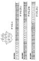
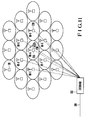
- Fig. 1 shows allocation of base stations of a cellular digital mobile communication system which employs a handoff method, i.e., a method of switching communication channels (to be referred to as channels hereinafter).
- a coverage area of the system constitutes a grid consisting of radio zones, i.e., cell sites of a large number of base stations 1.
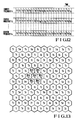
- Fig. 2A shows a format assigned to a base station A
- Fig. 2B shows a format assigned to base stations B, D, and F
- Fig. 2C shows a format assigned to base stations C, E and G.
- a frame having a length of 8T (to be referred to as an 8T frame hereinafter) constituted by time slots each having a length of 2T is repeated twice, and a frame having a length of 4T (to be referred to as a 4T frame hereinafter) of time slots each having a length of T are repeated eight times.
- the frame format is assigned to the base station 1 as described above, while the 8T frame is repeated twice, the adjacent base stations repeat the 4T frame. Therefore, all channel switching operations of the base stations can be completed within the 6T free time which is available during repetition of the 8T frame twice.
- a new channel B3 is designated for a mobile station which is moving by using a channel A1 at present.
- the mobile station switches the present channel to the channel B3, performs a communication test with the base station B, and then returns to the channel A1 when the first half of the continuous 2T time slots of the channel A1 is completed.
- the communication test can be performed using a plurality of time slots.
- the mobile station can continuously perform communication via the channel A1 and at the same time the communication test of the newly designated channel B3.
- the communication test for other channels than the channel B3 can be performed in the same manner as described above.
- Fig. 3 is a view showing control procedures of a first handoff sequence using the frame formats shown in Figs. 2A to 2C.
- a mobile station connected to the base station A via the channel A1 enters into a cell cite of base station B, this entrance is detected by an exchange.
- the exchange selects a free channel B3 of the base station B as a new channel.
- This detection technique is well known to those skilled in the art.
- the exchange designates the channel number B3 of the base station B to the mobile station via the base station A by using a signal in the channel A1.
- the exchange renders the base station B to transmit a test signal via the channel B3.
- the mobile station receives the channel B3 designated by utilizing the free time of the channel.
- the mobile station detects the test signal and sends back an acknowledge signal via the channel B3.
- the exchange which receives the acknowledge signal via the base station B designates switching to the mobile station by using the signal in the channel A1.
- the mobile station switches the channel from A1 to B3. In this manner, when the communication test is performed by utilizing the free time of the channel, the interruption time of communication can be shortened.
- Fig. 4 is a view showing control procedures of a second handoff sequence using the channel frame formats shown in Figs. 2A to 2C.
- a mobile station connected to the base station A via the channel A1 enters into a cell cite of the base station B
- this mobile station detects entrance into the cell cite of the base station B.
- This detection can be performed such that a control channel commonly and time-divisionally utilized by a plurality of base stations is monitored by using the channel free time and mean values of reception levels of the control channel transmitted from the respective base stations are compared.
- the mobile station which detects crossing between the cell sites requests a channel to the base station B.
- the base station B designates the channel number B3 to the mobile station.
- the request and the designation of the channel described above are performed by utilizing the channel free time, and therefore communication is not interfered.
- the mobile station then transmits a test signal by utilizing the free time of the channel A1 via the newly designated channel B3.
- the base station B detects this test signal, it sends back an acknowledge signal via the channel B3.
- the mobile station designates switching to the exchange via the base station A by using a signal in the channel A1.
- the mobile station then switches the channel from A1 to B3.
- the exchange which receives a signal for designating switching switches a communication line from the base station A to the base station B.
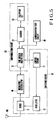
- Fig. 5 is a block diagram showing a mobile station for realizing the handoff sequences of Figs. 3 and 4.
- Reference numeral 10 denotes a switching circuit; 20, a communication circuit; and 30, a communication test circuit.
- An RF signal received by an antenna 100 is converted into an IF signal by a mixer 11 and demodulated by a modulator/demodulator 40.
- the demodulated signal is input to a time division multiplexer 21.
- the time division multiplexer 21 extracts a channel signal of present communication from outputs from the modulator/demodulator 40, and the extracted signal is sent to an encoder 22.
- the encoder 22 extracts a control signal which is then supplied to a control circuit 13.
- the encoder 22 converts an output from the time division multiplexer 21 into a speech signal and sends it to a telephone set 23.
- a speech signal as an output from the telephone set 23 is converted into a digital signal by the encoder 22, and the digital signal is input to the time division multiplexer 21.
- a control signal as an output from the control circuit 13 constituted by a microprocessor is input to the time division multiplexer 21. These signals are converted into a time division multiplexed signal by the time division multiplexer 21.
- the multiplexed signal is modulated by the modulator/demodulator 40.
- the modulated signal is converted into an RF signal by the mixer 11.
- the RF signal is transmitted from the antenna 100.
- Time-division multiplexing and modulation/demodulation techniques are not limited to any specific ones.
- the control circuit 13 Upon detection of the signal for designating the new channel number, when the present channel time slot is completed, the control circuit 13 changes a frequency of an oscillator 12 to tune the mixer 11 to a frequency of the new channel thereby to cause the communication test circuit 30 to connect with the new channel through the time division multiplexer 21.
- the communication test circuit 30 detects a test signal via the new channel, it sends back an acknowledge signal.
- the communication test circuit 30 transmits a test signal via the new channel and receives an acknowledge signal.
- the control circuit 13 changes the frequency of the oscillator 12 to tune to the frequency of the present channel and connects the communication circuit 20 to the present channel via the time division multiplexer 21 again.
- an SCPC Single Channel Per Carrier
- one channel is assigned to one carrier frequency.
- SCPC Single Channel Per Carrier
- N channels can be assigned to one carrier frequency by time division multiplexing.
- a time required for setting each mobile station in the transmission and reception states can be 1/N of the total communication time.
- the mobile station is kept in the standby state during the remaining time. According to the present invention, this free time is utilized to perform a communication test of a new channel by one receiver/transmitter without interfering the present communication.
- the time slots of the channel have equal intervals.
- the time slots of the present channel always overlap those of the new channel. Therefore, a communication test cannot be performed even if a free time is utilized.
- the time slots of the channels have unequal intervals. Even if any channel is newly assigned, a free time is available which does not involve overlapping between the time slots of the present and new channels. With this time slot assignment, a communication test can be performed without adversely affecting communication, and the interruption time can be almost eliminated.
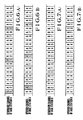
- Figs. 6A, 6B, 7A, and 7B show channel frame formats according to another embodiment of a handoff method of the present invention.
- Figs. 6A and 6B show frame formats of a downward channel from a base station A to a mobile station and an upward channel from the mobile station to the base station A.
- Figs. 7A and 7B show frame formats of a downward channel from a base station B to a mobile station and an upward channel from the mobile station to the base station B.
- each base station has a predetermined frequency difference.
- An 8T frame constituted by eight time slots each having a length of T are repeated to constitute each channel.
- a time difference between the downward and upward channels is one time slot. Therefore, after the mobile station receives information in a time slot of the downward channel, it transmits information in a time slot of the upward channel.
- a mobile station connected to the base station A via a channel A1 performs a communication test with the base station B during communication. After the mobile station receives information via the upward channel A1, it changes a frequency to that of the base station B and waits for a test signal via a new downward channel. When the mobile station detects a test signal via a new downward channel, it sends back an acknowledge signal via the new upward channel, immediately changes the channel to the channel of the base station A, and starts communication.
- Frequency switching generally requires a given period of time. Accordingly, when the mobile station transmits the signal via the upward channel A1 and then changes the frequency, the signal cannot be received via the downward channel B3 but by the channel B4. If newly assigned channels are B4, B5, and B6, the mobile station detects a test signal via a downward channel and sends back an acknowledge signal via an upward channel. The mobile station then switches the frequency to that of the base station A. In this case, information in the next time slot of the channel A1 can be received, and therefore no interruption caused by the communication test occurs.
- the mobile station detects a test signal via a downward channel and sends back an acknowledge signal via an upward channel.
- the mobile station then switches the frequency to that of the channel of the base station A. In this case, the mobile station cannot receive information in the next time slot of the channel A1. Therefore, one time slot of the channel A1 is lost and interruption occurs. However, such interruption has almost no effect on the communication quality and is negligible.
- a new downward channel can be detected within one frame upon frequency switching. However, even if a new downward channel is not detected upon a lapse of one frame, the present channel is forcibly restored, and a loss of the time slots can be reduced to one, thereby preventing degradation of communication quality.
- a mobile station is connected to the base station A and repeats downward channel reception (step 81) via the channel A1 and transmission via the upward channel (step 82) of the channel A1 of the frame formats of Figs. 6A, 6B, 7A, and 7B.
- the exchange detects this entrance and selects a free channel, e.g., B3 of the base station B as a new channel.
- the exchange designates the new channel to the mobile station by using a signal in the channel A1 via the base station A.
- the exchange causes the base station B to transmit a test signal via the channel B3.
- the mobile station tunes to the carrier of the downward channel B3 at the end of the time slots of the channel A1 in step 85.
- a timer is set at one frame period. The mobile station then waits for a test signal via the downward channel B3.
- the mobile station detects the test signal in step 87, the mobile station transmits an acknowledge signal via the new upward channel B3 in step 89.
- the mobile station returns to the channel A1 and continues communication.
- step 88 If the test signal is not detected upon a lapse of a one-frame period in step 88, the flow returns to step 81. In this case, no operation is performed, and the mobile station continues communication via the channel A1.
- the exchange receives the acknowledge signal via the base station B, the exchange designates switching (handoff) to the mobile station by using the signal in the channel A1.
- the exchange itself switches the channel from A1 to B3.
- the mobile station switches the channel from A1 to B3 (step 90). In this manner, when the communication test is performed while communication continues, an interruption time during the handoff sequence can be shortened.
- the mobile station communicates with the base station via a channel and at the same time receives a common downward control channel time-divisionally utilized by a plurality of base stations by using a channel free time (step 91).
- the mean values of the reception levels of the downward control channel of the base stations are compared to detect whether the mobile station enters into another cell site (step 92). For example, when a mobile station connected to the base station A via the channel A1 enters into a cell site of the base station B, the mobile station which has detected the entrance in the cell site in step 95 transmits a signal for requesting a new channel to the base station B via the control channel.
- the base station B designates the channel number B3 to the mobile station via the downward control channel and transmits a test signal via the channel B3.
- Exchange of signals between the mobile station and the base station B in steps 96 and 97 is performed by utilizing a free time of the channel.
- the mobile station which is designated with the new channel B3 in step 98 tunes the frequency to the carrier of the channel B3 (step 102) upon completion of the time slots of the channel A1.
- the timer is set at one frame period (step 103).
- the mobile station then waits for a test signal via the channel B3.
- the mobile station detects the test signal in step 104, the mobile station transmits an acknowledge signal via the channel B3 in step 101.
- the flow returns to step 96.
- the mobile station then continues communication via the channel A1.
- step 105 if the test signal is not detected upon a lapse of a one-frame period in step 105, the flow returns to step 91. No operation is performed, and the mobile station continues communication via the channel A1.
- the base station B receives the acknowledge signal, the base station B transmits a switching signal to the exchange and the mobile station.
- the exchange and the mobile station which receive the switching signal in step 99 switch the channel from A1 to B3 in step 106.
- Fig. 10 is a block diagram of a mobile station for realizing the handoff sequence shown in Fig. 9.
- Reference numeral 80 denotes a communication circuit; 30, a communication test circuit; and 90, a switching circuit.
- An RF signal received by an antenna 100 is converted into an IF signal by a mixer 40.
- the IF signal is demodulated by a modulator/demodulator 50.
- the demodulated signal is input to a time division multiplexer 60.
- the time division multiplexer 60 extracts a speech signal from the output from the modulator/demodulator 50.
- the speech signal is sent to a switch 91.
- the time division multiplexer 60 extracts a control signal from the output from the modulator/demodulator 50 and sends it to a control circuit 92.
- the switch 91 is controlled by the control circuit 92 to connect the time division multiplexer 60 to an encoder 81 or the communication test circuit 30.
- the time division multiplexer 60 is normally connected to the encoder 81, and the encoder 81 converts an output from the time division multiplexer 60 into a speech signal.
- the speech signal is sent to a telephone set 82.
- a speech signal as an output from the telephone set 82 is converted into a digital signal by the encoder 81. This digital signal is input to the time division multiplexer 60.
- a control signal as an output from the control circuit 92 is input to the time division multiplexer 60.
- These input signals are multiplexed by the time division multiplexer 60, and the multiplexed signal is modulated by the modulator/demodulator 50.
- the modulated signal is converted into an RF signal by the mixer 40.
- the RF signal is then transmitted from the antenna 100.
- Time-division multiplexing and modulation/demodulation techniques are not limited to any specific ones, and a detailed description will be omitted.
- the control circuit 92 Upon detection of the signal for designating a new channel number, when the time slots of the present channel are completed, the control circuit 92 changes a frequency of an oscillator 70 and tunes to the frequency of the new channel.
- the switch 91 connects the time division multiplexer 60 to the communication test circuit 30, and a timer 93 is set at one frame period. When a one-frame period has elapsed, the timer 93 outputs a detection signal to the control circuit 92.
- the communication test circuit 30 When the communication test circuit 30 detects a test signal via the new channel, it sends back or transmits an acknowledge signal to signal the end of communication test to the control circuit 92. When the communication test is completed, or a one-frame period has elapsed, the control circuit 92 changes the frequency of the oscillator 70 and tunes it to the frequency of the present channel.
- the time division multiplexer 60 is connected again to the encoder 81, and communication continues.
- the communication test of the new communication channel can be performed while communication continues. Therefore, a new channel can be switched during communication without degrading communication quality.
- Fig. 11 is a view showing a cellular digital mobile communication system employing a handoff method according to still another embodiment of the present invention.
- the cellular digital mobile communication system is constituted by an exchange 200, base stations 220, and a mobile station 230.
- the base station 220 includes at least one TDMA radio transmitter/receiver
- the mobile station 230 includes one TDMA radio transmitter/receiver.
- the mobile station 230 located within the cell site of a given base station 220 sets a communication channel with the BS-A and is wired via the exchange 200.
- a BS-A a base station located within the cell site of a given base station 220
- the mobile station 230 When the mobile station 230 is moved from the cell site of the BS-A to a cell site of an adjacent base station (e.g., BS-B), the mobile station 230 must detect that a new channel can be set with the BS-B. The mobile station 230 switches the channel with the BS-A into that with the BS-B and continues communication.
- Figs. 12 and 13 show first example of time division of carrier frequencies and spatial allocation of the time-divisionally carrier frequencies, respectively.
- the carrier frequencies to be used are given as f1, f2, f3,... f n , and twelve channels are time-divisionally multiplexed so as to synchronize with the carrier frequencies f1, f2, f3,... f n .
- Channel groups T1 to T12 are constituted by channels at identical timings. The channel groups T1 to T12 are assigned to the base stations such that the channel groups are not used in the adjacent base stations. In this case, the number of cell sites in a group having an identical frequency is 12.
- the mobile station 230 located in the cell site of the BS-A performs transmission or reception at the timing T1 of each of the carrier frequencies f1 to f n .
- the channel groups which may be newly assigned to this mobile station 230 are T4, T6, T7, T9, T10, and T11. Since these channel groups have differences of one or more time slots from the channel group T1 which has been used, respectively, a channel group newly assigned to the free time can be designated while communication continues via the channel group T1, and therefore a communication can be performed via the new channel group.
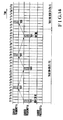
- Fig. 14 is a view showing a handoff sequence executed according to carrier frequency allocation shown in Figs. 12 and 13.
- a mobile station using a channel of the frequency f2 of the channel groups T1 (to be referred to as a channel (T1,f2) hereinafter) of the BS-A is moved to a cell site of the BS-B.
- the exchange detects this movement and selects a free channel, e.g., (T6,f1) as a new channel of the cell site of the BS-B, and designates this to the mobile station by using a signal in the channel (T1,f2).
- This detection by the exchange is well known to those skilled in the art, and a detailed description thereof will be omitted.
- the exchange transmits a test signal to the BS-B via the channel (T6,f1).
- the mobile station designated with the new channel (T6,f1) waits for a test signal transmitted via the channel (T6,f1) upon completion of the time slots of the channel (T1,f2).
- the mobile station detects the test signal, it transmits or sends back an acknowledge signal via the channel (T6,f1), returns to the channel (T1,f2), and continues communication.
- a communication test is performed through two frames in Fig. 14. However, a communication test may be completed within one frame or continues for three or more frames.
- the exchange receives the acknowledge signal via the channel (T6,f1) of the BS-B, the exchange designates switching to the mobile station by using a signal in the channel (T1,f2).
- the exchange itself switches the communication line from the BS-A to the BS-B.
- the mobile station switches the channel from (T1,f2) to (T6,f1). In this manner, when the communication test is performed while communication continues, an interruption time during the handoff sequence can be shortened.
- Figs. 15 and 16 are views showing second example for time division of carrier frequencies and spatial allocation of the frequency-divided carrier frequencies.
- the same time slots as the channel T i (i: an integer satisfying 1 ⁇ i ⁇ 12) are given as S i and R i .
- S2 represents that the carrier frequencies f12, f22,... f k2 ,... f n2 are time-divisionally multiplexed at the same time slots as in the channel T2.
- the channels at identical timings constitute channel groups T1 to T12, S1 to S12, and R1 to R12.
- the channel groups T1 to T12, S1 to S12, and R1 to R12 are assigned to the cell sites, as shown in Fig. 15.
- clusters each having a size of 12 are combined to constitute a cluster having a size of 36. Therefore, the number of cell sites at an identical frequency is 36. Similarly, it is possible to increase the number of cell sites at an identical frequency while the degree of multiplexing of channels is kept at 12.
- a plurality of channels are time-divisionally multiplexed so as to synchronize with the carrier frequencies, the channels at identical timings constitute channel groups, the channel groups are assigned to the cell sites such that the channel group is used as a unit, and the channel groups continuous on the time axis are not used by the adjacent cell sites.
- a handoff method method in a cellular digital mobile communication system wherein transmission timings of the DTMA radio transmitters/receivers are equal to each other within a given base station but are differentiated by one or more time slots between the adjacent base stations, so that an interruption time during the handoff sequence can be substantially eliminated while communication continues.
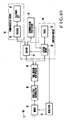
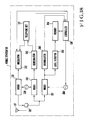
- Fig. 17 is a block diagram showing a cellular mobile communication system for practicing a handoff method according to still another embodiment of the present invention.
- the cellular mobile communication system is constituted by an exchange 110, N base stations 1201, 1202,... 120 N , and a mobile station 130.
- the N base stations 1201 to 120 N communicate with the mobile station 130 via communication and control channels uniquely assigned to these base stations.
- a downward signal of each control channel of the base station includes a flag 140 representing the presence/absence of a free channel of the base station. When the flag 140 is set at level "1", it indicates that a free channel is available. However, when the flag 140 is set at level "0", it indicates that a free channel is not available.
- a frequency f d is assigned to the downward communication channel of the base station 1203, and a frequency f u is assigned to the upward channel thereof.
- I frequencies are utilized again for the downward control channels.
- Frequencies f1, f2, f3, and f I are assigned to the base stations 1201, 1202, and 1203, and 120 I, respectively. Other frequency assignment operations are omitted.
- the mobile station 130 comprises an antenna 131, a hybrid circuit 132, a transmitter 133, a receiver 134, a level monitor 135, and a controller 136. The mobile station 130 communicates with a nearest base station by using the transmitter 133 and the receiver 134.
- the mobile station 130 receives the signals of the frequencies f1 to f I via the downward control channels of the base stations by using the level motor 135 upon switching.
- the mobile station 130 compares reception levels of the base stations having free communication channels and monitors movement between the cell sites based on the flags 140.
- the mobile station 130 transmits a switching request signal representing the base station in the changed cell site to the exchange via the upward communication channel.
- the level monitor 135 compares the reception levels of the base stations having free communication channels on the basis of the flags 140 and detects a change in cell site to that of the base station 1202 and transmits via the upward communication channel a switching request signal for requesting switching to the base station 1202.
- the base station 1203 receives the switching request signal, it signals this to the exchange 110.
- the exchange 110 selects a free communication channel of the base station 1202 and designates its number to the mobile station 130 via the base station 1203.
- the mobile station 130 switches the channel to the designated communication channel of the base station 1202.
- the mobile station can always monitor a change in cell site, and control of the handoff sequence is shared by the base and mobile stations, thereby preventing local concentration of a control amount.
- different frequencies are assigned to the control channels.
- the control channels may be assigned to an identical frequency by time-divisional multiplexing. In this case, the reception frequency of the level monitor need not be changed.
- Fig. 18 is a block diagram of the mobile station 130 shown in Fig. 17.
- the mobile station 130 comprises an antenna 131, a hybrid circuit 132, a mixer 331, a modulator 332, a mixer 341, a demodulator 342, a mixer 351, a demodulator 352, a level detector 353, an oscillator 350, an oscillator 330, a controller 136, and a telephone set 137.
- the mixer 331 and the modulator 332 constitute the transmitter 133.
- the mixer 341 and the demodulator 342 constitute the receiver 134.
- the mixer 351, the demodulator 352, the level detector 353, and the oscillator 350 constitute the level monitor 135.
- the oscillator 330 is used to control the mixers 331 and 342.
- An RF signal received by the antenna 131 is input to the mixers 341 and 351 through the hybrid circuit 132.
- the RF signal of the downward communication channel is mixed with an output from the oscillator 330 by the mixer 341 and is converted into an IF signal.
- the IF signal is demodulated by the demodulator 342.
- the demodulated signal is supplied to the telephone set 137.
- a control signal included in the communication channel is sent to the controller 136.
- a speech signal output from the telephone set 137 and a control signal output from the controller 136 are converted into an IF signal by the modulator 332.
- An output from the modulator 332 is mixed with an output from the oscillator 330 by the mixer 331.
- An output from the mixer 331 is transmitted as an RF signal from the antenna 131 via the hybrid circuit 132. Any modulation/demodulation techniques may be utilized, and a detailed description thereof will be omitted.
- One frequency may be assigned to one communication channel, or one frequency may be assigned to a plurality of communication channels by time division multiplexing.
- An RF channel of the downward control channel is mixed with an output from the oscillator 350 by the mixer 351, and the output from the mixer 351 is supplied to the demodulator 352 and the level detector 353.
- the output from the mixer 351 is demodulated by the demodulator 352 and is supplied to the controller 136 as a control signal including a base station identification code, and a flag representing the presence/absence of a free communication channel.
- the level of the output from the mixer 351 is detected by the level detector 353.
- a level detection singal is supplied to a memory 354.
- the controller 136 sequentially changes the oscillation frequencies of the oscillator 350 so as to sequentially receive signals via the downward control channel of each base station.
- the controller 136 When the controller 136 detects the base station identification code in the output from the demodulator 352, the controller 136 causes the memory 354 to store the corresponding output from the level detector 353 and the flag representing the presence/absence of the free communication channel in units of base station identification codes.
- the controller 136 compares the reception levels of the base stations having free communication channels, which are stored in the memory 354.
- the control circuit 136 thus monitors a change in cell site. When a change in sell site is detected, the controller 136 transmits a switching request signal including the designation base station identification code. If a plurality of reception levels of the respective base stations are stored and their mean values are compared, the influence of detection errors caused by fading is minimized.
- a plurality of flags representing the presence/absence of free communication channels are stored. Comparisons can be performed by using the latest flags. In this manner, when a change in cell site is monitored by the mobile station, concentration of control amounts during the handoff sequence can be prevented.
- the base station monitors a change in cell site upon comparison between the reception levels of the upward signals of the mobile station, this monitoring must be performed by a plurality of base stations and monitoring results must be concentrated. Therefore, when channel switching is frequently performed, the control amount is locally concentrated.
- each mobile station can compare the reception levels of the downward signals of the base stations to monitor a change in cell site, so that monitoring control can be shared by the base and mobile stations.
- the level monitor is arranged in the mobile station to receive the downward signals from other base stations excluding a given station while the mobile station communicates with the given station.
- the downward signal may be received by the level monitor via a communication channel, but preferably via a control channel which normally transmits the downward channel.
- the control channel is time-divisionally multiplexed by each base station throughout the cell sites, the reception frequency of the monitor need not be changed to simplify the apparatus arrangement.
- the base station transmits a downward signal including the flag representing the presence/absence of a free communication channel, and the mobile station compares the reception levels of the downward signals of the base stations having free communication channels. Therefore, a base station having no free communication channel cannot be selected as a designation station. In this manner, the mobile station monitors a change in cell site during communication. When the change in cell site is detected, the mobile station transmits a switching request signal and is switched to the designation base station having a free communication channel. Therefore, local concentration of the control amount during the handoff sequence can be prevented.
- a handoff method and a mobile station in a cellular digital mobile communication system substantially free from a local increase in control amount caused by an increase in the frequency of occurrence of channel switching.
Applications Claiming Priority (8)
| Application Number | Priority Date | Filing Date | Title |
|---|---|---|---|
| JP62301127A JPH01141422A (ja) | 1987-11-27 | 1987-11-27 | ディジタル移動通信システムの通話中チャネル切換方法および移動端末 |
| JP301127/87 | 1987-11-27 | ||
| JP4159/88 | 1988-01-11 | ||
| JP63004159A JPH0738738B2 (ja) | 1988-01-11 | 1988-01-11 | 移動通信システムの通話中チャネル切換え方法および移動端末 |
| JP7174/88 | 1988-01-14 | ||
| JP63007174A JPH01183221A (ja) | 1988-01-14 | 1988-01-14 | 移動通信システムおよび移動通信端末 |
| JP63066480A JPH01238329A (ja) | 1988-03-18 | 1988-03-18 | 移動通信システムの通話中チャネル切換え方法 |
| JP66480/88 | 1988-03-18 |
Publications (3)
| Publication Number | Publication Date |
|---|---|
| EP0318033A2 true EP0318033A2 (de) | 1989-05-31 |
| EP0318033A3 EP0318033A3 (en) | 1990-10-10 |
| EP0318033B1 EP0318033B1 (de) | 1995-09-13 |
Family
ID=27454028
Family Applications (1)
| Application Number | Title | Priority Date | Filing Date |
|---|---|---|---|
| EP88119679A Expired - Lifetime EP0318033B1 (de) | 1987-11-27 | 1988-11-25 | Verfahren zum Umschalten in einem digitalen Zellularmobilkommunikationssystem und mobile Einheit |
Country Status (3)
| Country | Link |
|---|---|
| US (2) | US5157661A (de) |
| EP (1) | EP0318033B1 (de) |
| DE (1) | DE3854465T2 (de) |
Cited By (22)
| Publication number | Priority date | Publication date | Assignee | Title |
|---|---|---|---|---|
| EP0330222A2 (de) * | 1988-02-25 | 1989-08-30 | Nec Corporation | Verfahren und Vorrichtung zur Funkfrequenzumschaltung |
| WO1990013187A1 (en) * | 1989-04-17 | 1990-11-01 | Telefonaktiebolaget Lm Ericsson | Method of maintaining an established connection in a mobile radio system comprising both analog and digital radio channels |
| WO1991000657A1 (en) * | 1989-06-26 | 1991-01-10 | Telefonaktiebolaget Lm Ericsson | Mobile assisted handoff |
| EP0430106A2 (de) * | 1989-11-24 | 1991-06-05 | Nippon Telegraph And Telephone Corporation | Funkkommunikationseinrichtung und Verkehrskanalumlegungsverfahren dafür |
| EP0439630A1 (de) * | 1989-08-25 | 1991-08-07 | Nippon Telegraph And Telephone Corporation | Regelungsverfahren eines funkkanalschalters |
| EP0448015A2 (de) * | 1990-03-19 | 1991-09-25 | Fujitsu Limited | Mobiles Funkkommunikationssystem |
| EP0471656A2 (de) * | 1990-08-16 | 1992-02-19 | Telefonaktiebolaget L M Ericsson | Verfahren und Anordnung zur Verbesserung der Zuverlässigkeit der Signalisierung in einem zellularen Mobil-Funktelefonsystem |
| EP0485351A1 (de) * | 1990-11-07 | 1992-05-13 | Telefonaktiebolaget L M Ericsson | Verfahren zum Verhindern von Interferenzen zwischen einer ersten und einer zweiten Mitteilung in einem mobilen Telefonsystem |
| WO1992010886A1 (en) * | 1990-12-04 | 1992-06-25 | Telenokia Oy | A radio system |
| US5129098A (en) * | 1990-09-24 | 1992-07-07 | Novatel Communication Ltd. | Radio telephone using received signal strength in controlling transmission power |
| EP0526202A2 (de) * | 1991-07-31 | 1993-02-03 | Nec Corporation | Frequenzsynthesizer mit lokaler Oszillatorschaltung zur Anwendung in einem Vielfachzugriffszeitmultiplexsystem |
| US5200957A (en) * | 1989-06-26 | 1993-04-06 | Telefonaktiebolaget L M Ericsson | Mobile assisted handoff |
| US5257401A (en) * | 1989-04-17 | 1993-10-26 | Telefonaktiebolaget L M Ericsson | Method of maintaining an established connection in a mobile radio system comprising both analog and digital radio channels |
| GB2281177A (en) * | 1993-07-14 | 1995-02-22 | Nec Corp | Seamless handoff method |
| EP0647080A2 (de) * | 1993-10-01 | 1995-04-05 | AT&T Corp. | Mobil synchronisiertes Weiterreichen in einem schnurlosen Kommunikationssystem |
| WO1995034180A2 (en) * | 1994-06-02 | 1995-12-14 | Nokia Telecommunications Oy | A method of selecting the transmission to be received in a mobile radio system, and a mobile station |
| GB2300999A (en) * | 1995-05-16 | 1996-11-20 | Nec Corp | Method of Soft Handoff in a Mobile Radio Communication System |
| EP0763300A1 (de) * | 1994-03-21 | 1997-03-19 | Omnipoint Corporation | Pcs-taschentelefon/mikrozellen-funkübertragungsprotokoll |
| WO1998000999A2 (en) * | 1996-06-28 | 1998-01-08 | Motorola Limited | Method and apparatus for monitoring channels to enable handoff in mobile communication systems |
| GB2324442A (en) * | 1997-01-29 | 1998-10-21 | Nec Corp | Cordless telephone operating in public and private telephone systems |
| US6144653A (en) * | 1993-11-01 | 2000-11-07 | Telefonakteibolaget Lm Ericsson | Method for communicating in a wireless communication system |
| CN1063002C (zh) * | 1993-06-14 | 2001-03-07 | 艾利森电话股份有限公司 | 直接序列码分多址系统中无缝转换的非连续传送 |
Families Citing this family (37)
| Publication number | Priority date | Publication date | Assignee | Title |
|---|---|---|---|---|
| FR2657211A1 (fr) * | 1990-01-18 | 1991-07-19 | Cit Alcatel | Procede de transfert de communication dans un reseau de radiotelephonie. |
| US5339353A (en) * | 1991-03-06 | 1994-08-16 | Fujitsu Limited | Mobile communication system |
| US5285469A (en) | 1991-06-03 | 1994-02-08 | Omnipoint Data Corporation | Spread spectrum wireless telephone system |
| JP3043171B2 (ja) * | 1992-02-25 | 2000-05-22 | 富士通株式会社 | 制御チャネルモニタ方式 |
| US5343513A (en) * | 1992-04-20 | 1994-08-30 | Hughes Aircraft Company | Channel compression and dynamic repartitioning for dual mode cellular radio |
| US5329635A (en) * | 1992-05-12 | 1994-07-12 | Motorola, Inc. | Seamless handoff for radio telephone systems |
| FR2699357B1 (fr) * | 1992-12-16 | 1995-01-13 | Alcatel Radiotelephone | Dispositif de recherche de connexion d'un terminal à un réseau d'un système de radiocommunication comprenant plusieurs réseaux. |
| FI92536C (fi) * | 1993-03-04 | 1994-11-25 | Nokia Telecommunications Oy | Menetelmä radiopuhelinjärjestelmässä |
| US5493563A (en) * | 1993-07-26 | 1996-02-20 | Motorola, Inc. | Method and apparatus for mobile assisted handoff in a communication system |
| US5854808A (en) * | 1993-09-14 | 1998-12-29 | Pacific Communication Sciences | Methods and apparatus for detecting the presence of a prescribed signal in a channel of a communications system |
| US5574750A (en) * | 1993-09-14 | 1996-11-12 | Pacific Communication Sciences, Inc. | Methods and apparatus for detecting a cellular digital packet data (CDPD) carrier |
| US6005856A (en) * | 1993-11-01 | 1999-12-21 | Omnipoint Corporation | Communication protocol for spread spectrum wireless communication system |
| US6021333A (en) * | 1993-11-01 | 2000-02-01 | Omnipoint Corporation | Method and system for transferring information within a mobile communication system |
| US6301242B1 (en) | 1998-07-24 | 2001-10-09 | Xircom Wireless, Inc. | Communication system with fast control traffic |
| US6094575A (en) * | 1993-11-01 | 2000-07-25 | Omnipoint Corporation | Communication system and method |
| US5577047A (en) * | 1993-11-10 | 1996-11-19 | Telefonaktiebolaget Lm Ericsson | System and method for providing macrodiversity TDMA radio communications |
| US5673307A (en) * | 1994-02-17 | 1997-09-30 | Spectralink Corporation | Handoff method for indoor cellular phone system |
| US6049715A (en) * | 1994-06-01 | 2000-04-11 | Nortel Networks Corporation | Method and apparatus for evaluating a received signal in a wireless communication utilizing long and short term values |
| JP3078177B2 (ja) * | 1994-07-01 | 2000-08-21 | 三菱電機株式会社 | 無線装置 |
| US5537415A (en) * | 1994-11-08 | 1996-07-16 | Microsoft Corporation | Multi-channel personal messaging unit |
| US5896368A (en) * | 1995-05-01 | 1999-04-20 | Telefonaktiebolaget Lm Ericsson | Multi-code compressed mode DS-CDMA systems and methods |
| US5883899A (en) * | 1995-05-01 | 1999-03-16 | Telefonaktiebolaget Lm Ericsson | Code-rate increased compressed mode DS-CDMA systems and methods |
| JP2713240B2 (ja) * | 1995-06-15 | 1998-02-16 | 日本電気株式会社 | 移動通信システム |
| US5812936A (en) * | 1995-09-19 | 1998-09-22 | Lucent Technologies, Inc. | Energy-efficient time-division radio that reduces the induction of baseband interference |
| US6016428A (en) * | 1995-10-18 | 2000-01-18 | Telefonaktiebolaget Lm Ericsson | Registration control of mobile stations in a wireless communication system |
| US5661724A (en) * | 1995-12-18 | 1997-08-26 | Ericsson Inc. | Satellite diversity scheme |
| US6108322A (en) * | 1996-06-28 | 2000-08-22 | Motorola, Inc. | Method of enabling handoff |
| JPH1032548A (ja) * | 1996-07-17 | 1998-02-03 | Toshiba Corp | 受信装置 |
| JPH10200937A (ja) * | 1997-01-16 | 1998-07-31 | Nec Corp | 隣接セルモニタ方法および時分割デジタル方式移動通信システム |
| US6044272A (en) * | 1997-02-25 | 2000-03-28 | Sbc Technology Resources, Inc. | Mobile assisted handoff system and method |
| JPH10257553A (ja) * | 1997-03-14 | 1998-09-25 | Rohm Co Ltd | 移動体通信システム及びその移動体端末 |
| JP2001231062A (ja) * | 2000-02-17 | 2001-08-24 | Nec Shizuoka Ltd | 携帯電話システム及びそのハンドオーバ方法 |
| FI110735B (fi) * | 2001-03-16 | 2003-03-14 | Nokia Corp | Kanavakoodekkien testisilmukoita |
| JP5233523B2 (ja) * | 2008-09-01 | 2013-07-10 | 富士通株式会社 | 無線基地局状態検出方法及びシステム |
| US8737296B2 (en) * | 2008-10-24 | 2014-05-27 | Qualcomm Incorporated | Method and apparatus for anchor cell designation in network MIMO |
| US8380200B1 (en) | 2010-07-08 | 2013-02-19 | Sprint Spectrum L.P. | Methods and systems for facilitating multi-technology handovers |
| US8841989B2 (en) * | 2013-02-04 | 2014-09-23 | American Messaging Services, Llc | Messaging devices and methods |
Citations (4)
| Publication number | Priority date | Publication date | Assignee | Title |
|---|---|---|---|---|
| EP0145098A2 (de) * | 1983-12-09 | 1985-06-19 | Telecommunications Radioelectriques Et Telephoniques T.R.T. | Verfahren für eine in beiden Richtungen wirksame Funkverbindung zwischen einer Feststation und einer Mobilstation |
| FR2566562A1 (fr) * | 1984-06-21 | 1985-12-27 | Int Standard Electric Corp | Systeme de radiotelephonie mobile cellulaire |
| WO1987005458A1 (en) * | 1986-03-03 | 1987-09-11 | Storno A/S | A method of operating a radio transmission or communication system including a central station and a plurality of individual remote stations, a radio transmission or communication system, and a remote station |
| EP0288904A2 (de) * | 1987-05-01 | 1988-11-02 | Motorola Inc. | Mikrozellulares Kommunikationssystem mit Makrodiversity |
Family Cites Families (14)
| Publication number | Priority date | Publication date | Assignee | Title |
|---|---|---|---|---|
| JPS53131703A (en) * | 1977-04-21 | 1978-11-16 | Nec Corp | Busy channel switching system |
| US4215244A (en) * | 1978-12-18 | 1980-07-29 | The United States Of America As Represented By The Secretary Of The Army | Self-adaptive mobile subscriber access system employing time division multiple accessing |
| US4414661A (en) * | 1981-07-02 | 1983-11-08 | Trancom Ab | Apparatus for communicating with a fleet of vehicles |
| JPS589442A (ja) * | 1981-07-09 | 1983-01-19 | Mitsubishi Electric Corp | 移動無線局の受信装置 |
| JPS58187033A (ja) * | 1982-04-26 | 1983-11-01 | Nippon Telegr & Teleph Corp <Ntt> | 移動通信制御方式 |
| JPS58191542A (ja) * | 1982-05-01 | 1983-11-08 | Nippon Telegr & Teleph Corp <Ntt> | 移動通信制御方式 |
| JPS59161138A (ja) * | 1983-03-04 | 1984-09-11 | Nippon Telegr & Teleph Corp <Ntt> | 移動通信方式の制御方式 |
| JPS59178027A (ja) * | 1983-03-28 | 1984-10-09 | Nippon Telegr & Teleph Corp <Ntt> | 移動無線通信方式 |
| US4475010A (en) * | 1983-05-05 | 1984-10-02 | At&T Bell Laboratories | High density cellular mobile radio communications |
| JPS59212041A (ja) * | 1983-05-18 | 1984-11-30 | Hitachi Ltd | 移動無線通信における導通試験方式 |
| US4682367A (en) * | 1985-11-13 | 1987-07-21 | General Electric Company | Mobile radio communications system with join feature |
| US4726050A (en) * | 1986-02-18 | 1988-02-16 | Motorola, Inc. | Scanning receiver allocation method and apparatus for cellular radiotelephone systems |
| DE3607687A1 (de) * | 1986-03-08 | 1987-09-10 | Philips Patentverwaltung | Verfahren und schaltungsanordnung zum weiterschalten einer funkverbindung in eine andere funkzelle eines digitalen funkuebertragungssystems |
| US4754450A (en) * | 1986-03-25 | 1988-06-28 | Motorola, Inc. | TDM communication system for efficient spectrum utilization |
-
1988
- 1988-11-25 DE DE3854465T patent/DE3854465T2/de not_active Expired - Lifetime
- 1988-11-25 EP EP88119679A patent/EP0318033B1/de not_active Expired - Lifetime
- 1988-11-28 US US07/276,833 patent/US5157661A/en not_active Ceased
-
1994
- 1994-10-20 US US08/326,396 patent/USRE36309E/en not_active Expired - Lifetime
Patent Citations (4)
| Publication number | Priority date | Publication date | Assignee | Title |
|---|---|---|---|---|
| EP0145098A2 (de) * | 1983-12-09 | 1985-06-19 | Telecommunications Radioelectriques Et Telephoniques T.R.T. | Verfahren für eine in beiden Richtungen wirksame Funkverbindung zwischen einer Feststation und einer Mobilstation |
| FR2566562A1 (fr) * | 1984-06-21 | 1985-12-27 | Int Standard Electric Corp | Systeme de radiotelephonie mobile cellulaire |
| WO1987005458A1 (en) * | 1986-03-03 | 1987-09-11 | Storno A/S | A method of operating a radio transmission or communication system including a central station and a plurality of individual remote stations, a radio transmission or communication system, and a remote station |
| EP0288904A2 (de) * | 1987-05-01 | 1988-11-02 | Motorola Inc. | Mikrozellulares Kommunikationssystem mit Makrodiversity |
Cited By (43)
| Publication number | Priority date | Publication date | Assignee | Title |
|---|---|---|---|---|
| EP0330222A3 (de) * | 1988-02-25 | 1991-04-10 | Nec Corporation | Verfahren und Vorrichtung zur Funkfrequenzumschaltung |
| EP0330222A2 (de) * | 1988-02-25 | 1989-08-30 | Nec Corporation | Verfahren und Vorrichtung zur Funkfrequenzumschaltung |
| WO1990013187A1 (en) * | 1989-04-17 | 1990-11-01 | Telefonaktiebolaget Lm Ericsson | Method of maintaining an established connection in a mobile radio system comprising both analog and digital radio channels |
| US5257401A (en) * | 1989-04-17 | 1993-10-26 | Telefonaktiebolaget L M Ericsson | Method of maintaining an established connection in a mobile radio system comprising both analog and digital radio channels |
| AU625085B2 (en) * | 1989-06-26 | 1992-07-02 | Telefonaktiebolaget Lm Ericsson (Publ) | Mobile assisted handoff |
| WO1991000657A1 (en) * | 1989-06-26 | 1991-01-10 | Telefonaktiebolaget Lm Ericsson | Mobile assisted handoff |
| US5200957A (en) * | 1989-06-26 | 1993-04-06 | Telefonaktiebolaget L M Ericsson | Mobile assisted handoff |
| US5258980A (en) * | 1989-08-25 | 1993-11-02 | Nippon Telegraph And Telephone Corporation | Radio channel switching control method |
| EP0439630A1 (de) * | 1989-08-25 | 1991-08-07 | Nippon Telegraph And Telephone Corporation | Regelungsverfahren eines funkkanalschalters |
| EP0439630A4 (en) * | 1989-08-25 | 1992-04-08 | Nippon Telegraph And Telephone Corporation | Wireless channel switch control method |
| US5231632A (en) * | 1989-11-24 | 1993-07-27 | Nippon Telegraph And Telephone Corporation | Radio communication equipment for a mobile station and traffic channel hand-off method using the same |
| EP0430106A3 (en) * | 1989-11-24 | 1992-05-27 | Nippon Telegraph And Telephone Corporation | Radio communication equipment for a mobile station and traffic channel hand-off method using the same |
| EP0430106A2 (de) * | 1989-11-24 | 1991-06-05 | Nippon Telegraph And Telephone Corporation | Funkkommunikationseinrichtung und Verkehrskanalumlegungsverfahren dafür |
| EP0727915A2 (de) * | 1990-03-19 | 1996-08-21 | Fujitsu Limited | Mobiles Funkkommunikationssystem |
| EP0727915A3 (de) * | 1990-03-19 | 1996-11-20 | Fujitsu Ltd | Mobiles Funkkommunikationssystem |
| EP0448015A3 (en) * | 1990-03-19 | 1992-07-15 | Fujitsu Limited | Mobile radio communication system |
| EP0448015A2 (de) * | 1990-03-19 | 1991-09-25 | Fujitsu Limited | Mobiles Funkkommunikationssystem |
| US5230082A (en) * | 1990-08-16 | 1993-07-20 | Telefonaktiebolaget L M Ericsson | Method and apparatus for enhancing signalling reliability in a cellular mobile radio telephone system |
| EP0471656A2 (de) * | 1990-08-16 | 1992-02-19 | Telefonaktiebolaget L M Ericsson | Verfahren und Anordnung zur Verbesserung der Zuverlässigkeit der Signalisierung in einem zellularen Mobil-Funktelefonsystem |
| EP0471656A3 (en) * | 1990-08-16 | 1993-01-13 | Telefonaktiebolaget L M Ericsson | A method and apparatus for enhancing signalling reliability in a cellular mobile radio telephone system |
| US5129098A (en) * | 1990-09-24 | 1992-07-07 | Novatel Communication Ltd. | Radio telephone using received signal strength in controlling transmission power |
| EP0485351A1 (de) * | 1990-11-07 | 1992-05-13 | Telefonaktiebolaget L M Ericsson | Verfahren zum Verhindern von Interferenzen zwischen einer ersten und einer zweiten Mitteilung in einem mobilen Telefonsystem |
| AU643844B2 (en) * | 1990-11-07 | 1993-11-25 | Telefonaktiebolaget Lm Ericsson (Publ) | A method of avoiding interference between a first and a second message in a mobile telephone system |
| AU645164B2 (en) * | 1990-12-04 | 1994-01-06 | Nokia Telecommunications Oy | A radio system |
| WO1992010886A1 (en) * | 1990-12-04 | 1992-06-25 | Telenokia Oy | A radio system |
| EP0526202A3 (en) * | 1991-07-31 | 1993-03-31 | Nec Corporation | Local oscillating frequency synthesizer for use in a tdma system |
| EP0526202A2 (de) * | 1991-07-31 | 1993-02-03 | Nec Corporation | Frequenzsynthesizer mit lokaler Oszillatorschaltung zur Anwendung in einem Vielfachzugriffszeitmultiplexsystem |
| US5270669A (en) * | 1991-07-31 | 1993-12-14 | Nec Corporation | Local oscillating frequency synthesizer for use in a TDMA system |
| CN1063002C (zh) * | 1993-06-14 | 2001-03-07 | 艾利森电话股份有限公司 | 直接序列码分多址系统中无缝转换的非连续传送 |
| GB2281177A (en) * | 1993-07-14 | 1995-02-22 | Nec Corp | Seamless handoff method |
| EP0647080A2 (de) * | 1993-10-01 | 1995-04-05 | AT&T Corp. | Mobil synchronisiertes Weiterreichen in einem schnurlosen Kommunikationssystem |
| EP0647080A3 (de) * | 1993-10-01 | 1995-10-25 | At & T Corp | Mobil synchronisiertes Weiterreichen in einem schnurlosen Kommunikationssystem. |
| US6144653A (en) * | 1993-11-01 | 2000-11-07 | Telefonakteibolaget Lm Ericsson | Method for communicating in a wireless communication system |
| EP0763300A1 (de) * | 1994-03-21 | 1997-03-19 | Omnipoint Corporation | Pcs-taschentelefon/mikrozellen-funkübertragungsprotokoll |
| EP0763300A4 (de) * | 1994-03-21 | 1999-12-08 | Omnipoint Corp | Pcs-taschentelefon/mikrozellen-funkübertragungsprotokoll |
| WO1995034180A3 (en) * | 1994-06-02 | 1996-02-01 | Nokia Telecommunications Oy | A method of selecting the transmission to be received in a mobile radio system, and a mobile station |
| WO1995034180A2 (en) * | 1994-06-02 | 1995-12-14 | Nokia Telecommunications Oy | A method of selecting the transmission to be received in a mobile radio system, and a mobile station |
| GB2300999A (en) * | 1995-05-16 | 1996-11-20 | Nec Corp | Method of Soft Handoff in a Mobile Radio Communication System |
| GB2300999B (en) * | 1995-05-16 | 1997-09-03 | Nec Corp | A mobile radio communications system |
| US5844898A (en) * | 1995-05-16 | 1998-12-01 | Nec Corporation | Method of radio channel switching over in a mobile radio communications system |
| WO1998000999A2 (en) * | 1996-06-28 | 1998-01-08 | Motorola Limited | Method and apparatus for monitoring channels to enable handoff in mobile communication systems |
| WO1998000999A3 (en) * | 1996-06-28 | 1998-03-26 | Motorola Ltd | Method and apparatus for monitoring channels to enable handoff in mobile communication systems |
| GB2324442A (en) * | 1997-01-29 | 1998-10-21 | Nec Corp | Cordless telephone operating in public and private telephone systems |
Also Published As
| Publication number | Publication date |
|---|---|
| US5157661A (en) | 1992-10-20 |
| EP0318033A3 (en) | 1990-10-10 |
| EP0318033B1 (de) | 1995-09-13 |
| DE3854465T2 (de) | 1996-05-02 |
| DE3854465D1 (de) | 1995-10-19 |
| USRE36309E (en) | 1999-09-21 |
Similar Documents
| Publication | Publication Date | Title |
|---|---|---|
| USRE36309E (en) | Handoff method for cellular digital mobile communication system and mobile station | |
| US5454026A (en) | Mobile communication congestion control system | |
| EP0448015B1 (de) | Mobiles Funkkommunikationssystem | |
| US5719859A (en) | Time division multiple access radio communication system | |
| US4955082A (en) | Mobile communication system | |
| EP0722648B1 (de) | Funkkommunikationsgerät und verfahren zum weiterreichen von einem system an ein anderes | |
| US20050164697A1 (en) | Communication apparatus and communication method | |
| US5383221A (en) | Mobile station unit and channel switching method | |
| US5446769A (en) | Method for providing hand-offs in a frequency hopping communication system | |
| US5729539A (en) | Method of scheduling signal quality measurements in a TDMA communication system | |
| KR100254575B1 (ko) | 이동통신 시스템의 채널대체방법, 이동통신망 및 이동국 | |
| EP1303152A1 (de) | Verfahren zur Beobachtung von Signalen zwischen Kommunikationssystemen, die entsprechend unterschiedlicher Zeitraster operieren | |
| EP1223686B1 (de) | Mobiles Kommunikationssystem unter Verwendung eines Verfahrens zur Feststations-Frequenzkorrektur | |
| KR100291613B1 (ko) | 전기통신시스템및이전기통신시스템에사용하기위한주국및종국 | |
| JPH1118144A (ja) | 基地局間同期確立方法及びシステム | |
| JPS58187033A (ja) | 移動通信制御方式 | |
| JPS59161138A (ja) | 移動通信方式の制御方式 | |
| WO1987005181A1 (en) | Scanning receiver allocation method and apparatus for cellular radiotelephone systems | |
| JPH0767169A (ja) | 無線通信装置 | |
| JP2993469B2 (ja) | 基地局間同期確立方法及びシステム | |
| JP2002300072A (ja) | Hf無線回線用送受信装置 | |
| JP2000069544A (ja) | 無線リソース割当制御方法 | |
| JPH099330A (ja) | 移動通信システムの無線ゾーン間チャネル切替 方式 | |
| JPH0738738B2 (ja) | 移動通信システムの通話中チャネル切換え方法および移動端末 | |
| JP2501369B2 (ja) | 移動通信における通信中チャネル切替え方式 |
Legal Events
| Date | Code | Title | Description |
|---|---|---|---|
| PUAI | Public reference made under article 153(3) epc to a published international application that has entered the european phase |
Free format text: ORIGINAL CODE: 0009012 |
|
| 17P | Request for examination filed |
Effective date: 19881125 |
|
| AK | Designated contracting states |
Kind code of ref document: A2 Designated state(s): DE GB SE |
|
| PUAL | Search report despatched |
Free format text: ORIGINAL CODE: 0009013 |
|
| AK | Designated contracting states |
Kind code of ref document: A3 Designated state(s): DE GB SE |
|
| 17Q | First examination report despatched |
Effective date: 19920917 |
|
| GRAA | (expected) grant |
Free format text: ORIGINAL CODE: 0009210 |
|
| AK | Designated contracting states |
Kind code of ref document: B1 Designated state(s): DE GB SE |
|
| REF | Corresponds to: |
Ref document number: 3854465 Country of ref document: DE Date of ref document: 19951019 |
|
| PLBE | No opposition filed within time limit |
Free format text: ORIGINAL CODE: 0009261 |
|
| STAA | Information on the status of an ep patent application or granted ep patent |
Free format text: STATUS: NO OPPOSITION FILED WITHIN TIME LIMIT |
|
| 26N | No opposition filed | ||
| REG | Reference to a national code |
Ref country code: GB Ref legal event code: IF02 |
|
| PGFP | Annual fee paid to national office [announced via postgrant information from national office to epo] |
Ref country code: DE Payment date: 20071122 Year of fee payment: 20 |
|
| PGFP | Annual fee paid to national office [announced via postgrant information from national office to epo] |
Ref country code: SE Payment date: 20071106 Year of fee payment: 20 |
|
| PGFP | Annual fee paid to national office [announced via postgrant information from national office to epo] |
Ref country code: GB Payment date: 20071121 Year of fee payment: 20 |
|
| REG | Reference to a national code |
Ref country code: GB Ref legal event code: PE20 Expiry date: 20081124 |
|
| PG25 | Lapsed in a contracting state [announced via postgrant information from national office to epo] |
Ref country code: GB Free format text: LAPSE BECAUSE OF EXPIRATION OF PROTECTION Effective date: 20081124 |