EP0318013A2 - Höhenregelungssystem für Fahrzeuge mit vom Fahrverhalten abhängiger veränderlicher Sensivität - Google Patents
Höhenregelungssystem für Fahrzeuge mit vom Fahrverhalten abhängiger veränderlicher Sensivität Download PDFInfo
- Publication number
- EP0318013A2 EP0318013A2 EP88119612A EP88119612A EP0318013A2 EP 0318013 A2 EP0318013 A2 EP 0318013A2 EP 88119612 A EP88119612 A EP 88119612A EP 88119612 A EP88119612 A EP 88119612A EP 0318013 A2 EP0318013 A2 EP 0318013A2
- Authority
- EP
- European Patent Office
- Prior art keywords
- vehicular
- height
- range
- target
- vehicle
- Prior art date
- Legal status (The legal status is an assumption and is not a legal conclusion. Google has not performed a legal analysis and makes no representation as to the accuracy of the status listed.)
- Granted
Links
- 230000035945 sensitivity Effects 0.000 title description 7
- 230000001105 regulatory effect Effects 0.000 claims abstract description 32
- 230000001133 acceleration Effects 0.000 claims description 100
- 239000000725 suspension Substances 0.000 claims description 57
- 239000012530 fluid Substances 0.000 claims description 26
- 238000012544 monitoring process Methods 0.000 claims description 12
- 230000004044 response Effects 0.000 claims description 9
- 230000000630 rising effect Effects 0.000 abstract description 4
- 238000000034 method Methods 0.000 description 9
- 230000008569 process Effects 0.000 description 9
- 238000009423 ventilation Methods 0.000 description 7
- 239000006096 absorbing agent Substances 0.000 description 6
- 230000035939 shock Effects 0.000 description 6
- 206010034719 Personality change Diseases 0.000 description 5
- 238000004891 communication Methods 0.000 description 4
- 238000013016 damping Methods 0.000 description 4
- 230000000903 blocking effect Effects 0.000 description 2
- 238000001514 detection method Methods 0.000 description 2
- 238000005096 rolling process Methods 0.000 description 2
- 238000009987 spinning Methods 0.000 description 2
- 230000015556 catabolic process Effects 0.000 description 1
- 230000008859 change Effects 0.000 description 1
- 230000001276 controlling effect Effects 0.000 description 1
- 238000006731 degradation reaction Methods 0.000 description 1
- 238000010586 diagram Methods 0.000 description 1
- 238000006073 displacement reaction Methods 0.000 description 1
- 238000001035 drying Methods 0.000 description 1
- 238000005516 engineering process Methods 0.000 description 1
- 238000002474 experimental method Methods 0.000 description 1
- 230000000977 initiatory effect Effects 0.000 description 1
- 238000012986 modification Methods 0.000 description 1
- 230000004048 modification Effects 0.000 description 1
- 230000001960 triggered effect Effects 0.000 description 1
Images

Classifications
-
- B—PERFORMING OPERATIONS; TRANSPORTING
- B60—VEHICLES IN GENERAL
- B60G—VEHICLE SUSPENSION ARRANGEMENTS
- B60G17/00—Resilient suspensions having means for adjusting the spring or vibration-damper characteristics, for regulating the distance between a supporting surface and a sprung part of vehicle or for locking suspension during use to meet varying vehicular or surface conditions, e.g. due to speed or load
- B60G17/015—Resilient suspensions having means for adjusting the spring or vibration-damper characteristics, for regulating the distance between a supporting surface and a sprung part of vehicle or for locking suspension during use to meet varying vehicular or surface conditions, e.g. due to speed or load the regulating means comprising electric or electronic elements
- B60G17/016—Resilient suspensions having means for adjusting the spring or vibration-damper characteristics, for regulating the distance between a supporting surface and a sprung part of vehicle or for locking suspension during use to meet varying vehicular or surface conditions, e.g. due to speed or load the regulating means comprising electric or electronic elements characterised by their responsiveness, when the vehicle is travelling, to specific motion, a specific condition, or driver input
-
- B—PERFORMING OPERATIONS; TRANSPORTING
- B60—VEHICLES IN GENERAL
- B60G—VEHICLE SUSPENSION ARRANGEMENTS
- B60G2400/00—Indexing codes relating to detected, measured or calculated conditions or factors
- B60G2400/10—Acceleration; Deceleration
- B60G2400/102—Acceleration; Deceleration vertical
-
- B—PERFORMING OPERATIONS; TRANSPORTING
- B60—VEHICLES IN GENERAL
- B60G—VEHICLE SUSPENSION ARRANGEMENTS
- B60G2400/00—Indexing codes relating to detected, measured or calculated conditions or factors
- B60G2400/10—Acceleration; Deceleration
- B60G2400/104—Acceleration; Deceleration lateral or transversal with regard to vehicle
-
- B—PERFORMING OPERATIONS; TRANSPORTING
- B60—VEHICLES IN GENERAL
- B60G—VEHICLE SUSPENSION ARRANGEMENTS
- B60G2400/00—Indexing codes relating to detected, measured or calculated conditions or factors
- B60G2400/10—Acceleration; Deceleration
- B60G2400/106—Acceleration; Deceleration longitudinal with regard to vehicle, e.g. braking
-
- B—PERFORMING OPERATIONS; TRANSPORTING
- B60—VEHICLES IN GENERAL
- B60G—VEHICLE SUSPENSION ARRANGEMENTS
- B60G2400/00—Indexing codes relating to detected, measured or calculated conditions or factors
- B60G2400/25—Stroke; Height; Displacement
- B60G2400/252—Stroke; Height; Displacement vertical
-
- B—PERFORMING OPERATIONS; TRANSPORTING
- B60—VEHICLES IN GENERAL
- B60G—VEHICLE SUSPENSION ARRANGEMENTS
- B60G2500/00—Indexing codes relating to the regulated action or device
- B60G2500/30—Height or ground clearance
-
- B—PERFORMING OPERATIONS; TRANSPORTING
- B60—VEHICLES IN GENERAL
- B60G—VEHICLE SUSPENSION ARRANGEMENTS
- B60G2600/00—Indexing codes relating to particular elements, systems or processes used on suspension systems or suspension control systems
- B60G2600/02—Retarders, delaying means, dead zones, threshold values, cut-off frequency, timer interruption
-
- B—PERFORMING OPERATIONS; TRANSPORTING
- B60—VEHICLES IN GENERAL
- B60G—VEHICLE SUSPENSION ARRANGEMENTS
- B60G2800/00—Indexing codes relating to the type of movement or to the condition of the vehicle and to the end result to be achieved by the control action
- B60G2800/24—Steering, cornering
Definitions
- the present invention relates generally to a vehicular height regulation system for regulating the vehicular height within a predetermined target height range. More specifically, the invention relates to a vehicular height regulation system which is variable of sensitivity level in detecting vehicular height change out of the target height range.
- the system monitors vehicular height level and compares the monitored height level with a predetermined upper and lower limit defining a target height range set about a predetermined target height.
- a predetermined upper and lower limit defining a target height range set about a predetermined target height.
- height adjustment for rising the vehicular height is performed so as to regulate the vehicular height within the target height range.
- height adjustment is performed for lowering the height to the upper limit.
- vehicular height regulation system has fixed height range to define the deadband about the target height level regardless of the vehicular driving condition. Therefore, sensitivity level of vehicular height variation for detecting vehicular height varying out of or into the target height range is constant at all vehicular driving condition.
- a difficulty is encountered in determining the height range to be set about the target height level. Namely, when the height range is set at excessively narrow, then the vehicular height control system becomes excessively sensitive to the height variation so as to carry out height regulating operation to maintain the vehicular attitude even during concerning. This causes difficulty for the driver to realize the critical speed for passing the corner.
- the control system may allow substantial vehicular height variation and thus allows substantial vehicular attitude change to cause degradation of the riding comfort.
- Another object of the invention is to provide a vehicular height regulating system which is variable of a target height range set about a target height level for adapting the sensitivity level to the vehicular driving condition.
- a further object of the invention is to provide a vehicular height regulating system which is variable of the sensitivity level depending upon a vehicular driving condition reflecting parameter, such as an acceleration exerted on the vehicular body.
- a vehicular height regulating system monitors a vehicular height level.
- the monitored height level is compared with upper and lower criteria which are higher than and lower than a predetermined target height level in a given magnitude.
- the system generally performs height adjustment for rising or lowering the actual vehicular height when the monitored vehicular height is out of a target height range defined by the upper and lower criteria.
- the system also monitors an a preselected vehicular driving parameter which reflects vehicular running condition. The system adjusts the upper and lower criteria depending upon the monitored vehicular driving parameter.
- a vehicle height regulation system comprising: a suspension system interposed between a vehicle body and a suspension member rotatably supporting a vehicular wheel, the suspension system including a variable pressure chamber filled with a working fluid for producing a suspension force for suspending the vehicular body on the suspension member a fluid circuit including a pressurized working fluid source and connected to the variable pressure chamber for adjusting pressure in the variable pressure chamber and whereby adjusting suspension force to be produced by in the variable pressure chamber a first sensor for monitoring vehicular body height level to produce a first sensor signal representative thereof a second sensor for monitoring preselected vehicular driving parameter representative of the vehicle driving condition to produce a second sensor signal representative thereof a controller means for setting a target vehicular height range about a predetermined target height level on the basis of the second sensor signal value, and controls the fluid circuit for adjusting the suspension force to maintain the vehicular height within the target vehicular height range on the basis of the first sensor signal value.
- a vehicle height regulation system comprising: a suspension system interposed between a vehicle body and a suspension member, rotatably supporting a vehicular wheel the suspension system including a variable pressure chamber filled with a working fluid for producing a suspension force for suspending the vehicular body on the suspension member; a fluid circuit including a pressurized working fluid source and connected to the variable pressure chamber for adjusting pressure in the variable pressure chamber and whereby adjusting suspension force to be produced by in the variable pressure chamber; a first sensor for monitoring vehicular body height level to produce a first sensor signal representative thereof; a second sensor for monitoring preselected vehicular driving unstability factor to produce a second sensor signal representative thereof; a controller means for setting a target vehicular height range about a predetermined target height level on the basis of the second sensor signal value, and controls the fluid circuit for adjusting the suspension force to maintain the vehicular height within the target vehicular height range on the basis of the first sensor signal value.
- a vehicle height regulation system comprising: a suspension system interposed between a vehicle body and a suspension member rotatably supporting a vehicular wheel, the suspension system including a variable pressure chamber filled with a working fluid for producing a suspension force for suspending the vehicular body on the suspension member; a fluid circuit including a pressurized working fluid source and connected to the variable pressure chamber for adjusting pressure in the variable pressure chamber and whereby adjusting suspension force to be produced by in the variable pressure chamber; a first sensor for monitoring vehicular body height level to produce a first sensor signal representative thereof; a second sensor for monitoring an acceleration to be exerted on the vehicular body to to produce a second sensor signal representative thereof; a controller means for setting a target vehicular height range about a predetermined target height level on the basis of the second sensor signal value, and controls the fluid circuit for adjusting the suspension force to maintain the vehicular height within the target vehicular height range on the basis of the first sensor signal value.
- the controller means initially sets the target height range at a narrowest range and to set wider range in response to increasing of the acceleration.
- the controller means maintains the target height range at a narrowest range when the acceleration is maintained smaller than or equal to a predetermined threshold and set to a wider range when the acceleration is greater than the threshold.
- the controller means initially set the narrowest target height range at minimum acceleration and linearly expands the target height range. The controller means expands the target height range in proportion to increasing of the acceleration.
- the second sensor monitors at least one of the lateral acceleration, longitudinal acceleration, or vertical acceleration.
- the second sensor monitors a laterally exerted, longitudinally exerted and vertically exerted accelerations to adjust the target height range in response to any one of the laterally exerted, longitudinally exerted and vertically exerted accelerations
- a vehicular height regulation system is applied for vehicular suspension systems 1FL, 1FR, 1RL and 1RR which suspend a vehicular body 2 on front left, front right, rear left and rear right wheels (not shown).
- the suspension systems 1FL, 1FR, 1RL and 1RR will be represented by the reference numeral "1" as generally referred to.
- Each suspension system 1 comprises a hydraulic shock absorber 4 and a pneumatic chamber 3 defined above the shock absorber.
- the hydraulic shock absorber 4 may be a variable damping force shock absorber which is variable of damping characteristics depending upon the vehicular driving condition.
- Such variable damping force shock absorber will be automatically adjustable of the suspension mode for hardening and softening depending upon the vehicular driving conditions.
- the variable damping force shock absorber and control operation thereof have been disclosed in the following co-pending applications and published applications.
- the pneumatic chamber 3 is defined by means of a rolling diaphragm 5.
- the pneumatic chamber 3 is communicated with a compressor 6 as a source of pressurized gas, such as air, via a pneumatic circuit.
- the compressor 6 is designed to be driven by an electric motor 17.
- the motor 17 is driven by an electric power supplied from a vehicular battery 15 supplied via a relay 16.
- a driver 7, e.g. air driver, is disposed in the pneumatic circuit at the orientation downstream of the compressor 6 for drying the pressurized gas supplied from the compressor.
- pressure control valves 8FL, 8FR, 8RL and 8RR are disposed in the pneumatic circuit in the vicinity of the respective inlets of the associated pneumatic chamber 3 for introducing and ventilating the pressurized gas thereinto and therefrom.
- a ventilation control valve 9 is provided in a ventilation port of the pneumatic circuit for establishing and blocking fluid communication between the pneumatic circuit and atmosphere.
- the pressure control valves 8FL, 8FR, 8RL and 8RR and the ventilation control valve 9 are cooperated with electromagnetic solenoids 10 and 11. These solenoids 10 and 11 are operative for switching valve positions of respectively associated pressure control valves 8FL, 8FR, 8RL and 8RR and the ventilation control valve 9.
- stroke sensors 14FL, 14FR, 14RL and 14RR are provided in order to monitor relative distance between the vehicular body 2 and suspension members (not shown) which rotatably support front left, front right, rear left and rear right wheels.
- the stroke sensors 14FL, 14FR, 14RL and 14RR may comprise potentiometer for varying outputs depending upon the relative distances between the vehicular body 2 and the suspension members.
- the outputs of the stroke sensors 14FL, 14FR, 14RL and 14RR will be hereafter referring to as "vehicular height indicative signals h FL , h FR , h RL and h RR .
- These stroke sensors 14FL, 14FR, 14RL and 14RR are connected to a control unit 25 which will be discussed later.
- the control unit 25 is also connected to a lateral acceleration sensor 21, a longitudinal acceleration sensor 22 and vertical acceleration sensors 23FR, 23RL and 23RR.
- the lateral acceleration sensor 21 is provided at appropriate position of the vehicular body and monitors lateral acceleration exerted on the vehicular body 2.
- the lateral acceleration sensor 21 outputs a lateral acceleration signal g y indicative of the monitored lateral acceleration.
- the longitudinal acceleration sensor 22 monitors longitudinal acceleration to produce a longitudinal acceleration indicative signal g x indicative of the monitored longitudinal acceleration.
- respective vertical acceleration sensors 23FR, 23RL and 23RR are provided in the vicinity of the suspension systems so as to monitor vertical accelerations exerted on the vehicular body at the positions of the front right, rear left and rear right suspension systems.
- the output signals of the vertical acceleration sensors 23FR, 23RL and 23RR will be hereafter referred to as “front right acceleration indicative signal g zFR”, "rear left acceleration indicative signal g zRL” and “rear right acceleration indicative signal g zRR .
- the control unit 25 comprises a microprocessor 26 and driver circuits 29a, 29b, 29c, 29d, 30 and 31.
- the control unit 25 also includes a multiplexer 27 for multiplexing the input signals, i.e. the vehicular height indicative signals h FL , h FR , h RL and h RR , the lateral acceleration indicative signal g y , the longitudinal acceleration indicative signal g x and the vertical acceleration indicative signals g zFR , g zRL and g zRR to selectively input to the microprocessor 26 via an analog-to-digital (A/D) converter 28.
- A/D analog-to-digital
- the driver circuits 29a, 29b, 29c and 29d are respectively connected to solenoides 10 of the pressure control valves 8FL, 8FR, 8RL and 8RR for feeding front left, front right, rear left and rear right driver signals to control valve positions thereof.
- the driver circuit 30 is connected to the ventilation control valve 9 for feeding driver signal to the latter to switch the valve position between a close position blocking communication between the pneumatic circuit and atmosphere.
- the driver circuit 31 is connected to a relay coil of the relay 16 for energizing and denergizing the relay coil.
- the microprocessor 26 comprises an input/output interface 35, an arithmetic circuit 36 and memory unit 27.
- the microprocessor 26 performs suspension control operation based on the input signals, i.e. the vehicular height indicative signals h FL , h FR , h RL and h RR , the lateral acceleration indicative signal g y , the longitudinal acceleration indicative signal g x and the vertical acceleration indicative signals g zFR , g zRL and g zRR for adjusting the vehicular height so that the vehicular height at respective suspension systems 1FL, 1FR, 1RL and 1RR can be maintained within a predetermined target height range defined about a target height H0.
- the target height range is defined by an upper and a lower height criteria H U and H L .
- the microprocessor 26 may also performs control for suppressing attitude change of the vehicular body, e.g. anti-rolling control based on the lateral acceleration, anti-pitching control based on the longitudinal acceleration, bouncing suppressive control based on the vertical acceleration.
- control for suppressing attitude change of the vehicular body e.g. anti-rolling control based on the lateral acceleration, anti-pitching control based on the longitudinal acceleration, bouncing suppressive control based on the vertical acceleration.
- microprocessor 26 performs various controls as set forth above, the following discussion will be concentrated to vehicular height control for maintaining the vehicular height within the target height range in order to facilitate better understanding of the invention and to avoid unnecessary confusion.
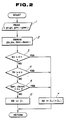
- Fig. 2 shows a routine for setting the target vehicular height range.
- the shown routine is triggered every given timing, e.g. every 0.5 sec. interrupting a main program which governs various control programs.
- the lateral acceleration indicative signal g y , the longitudinal acceleration indicative signal g x , and the front right, rear left, and rear right vertical acceleration indicative signals g zFR , g zRL and g zRR converted into digital form by the A/D converter 28 are read out at a step 1002.
- a lateral acceleration data G y a longitudinal acceleration data G x and front right , rear left, and rear right vertical acceleration data G zFR , G zRL and G zRR are derived at a step 1004.
- the lateral acceleration data G y derived at the step 1004 is compared with a lateral acceleration threshold ⁇ y at a step 1006.
- the lateral acceleration threshold ⁇ y is a preset valve for discriminating vehicular cornering conditions between a condition close to critical point where the lateral acceleration is substantially great to cause lateral slid or spinning of the vehicle and steady cornering condition.
- the practical value is derived on the basis of experiments and set at a value of 0.5G for example.
- the longitudinal acceleration data G x is compared with a longitudinal acceleration threshold ⁇ x at a step 1008.
- the longitudinal acceleration threshold ⁇ x is determined at a value for discriminating vehicular accelerating or decelerating condition close to critical point where wheel spinning, substantial squat or substantial nose dive causing unstability of the vehicle may be caused, and steady acceleration or deceleration state.
- the longitudinal acceleration threshold ⁇ x is set at a experimentally obtained value, e.g. 0.5G.
- the longitudinal acceleration data G x is smaller than or equal to the longitudinal acceleration threshold ⁇ x as checked at the step 1008, respective of the front right, rear left and rear right vertical acceleration data G zFR , G zRL and G zRR are compared with a vertical acceleration threshold ⁇ z at a step 1010.
- the vertical acceleration threshold ⁇ z is set at a predetermined value close to a critical point where vehicular attitude change becomes substantial to cause the vehicle unstable condition. Practically, the vertical acceleration threshold ⁇ z is set at an experimentally obtained value, e.g. 0.5G.
- a deadband adjusting value DZ which is to be added and subtracted to and from the target height value H0 to derive the upper and lower criteria H U and H L , is set at a value ⁇ 1, at a step 1012.
- the deadband adjusting data DZ is set at a value ⁇ 2 which is greater than the value ⁇ 1 and thus widen the deadband, at a step 1014.
- the value ⁇ 1 is set at a value (e.g.
- the value ⁇ 2 is set at a value Z (e.g. 40 mm) which may widen the deadband or the target height range to allow the vehicular body to cause attitude change which may notice the driver that the vehicle is driven at a condition close to the critical point.
- the deadband or the target height range is set on the basis of the derived deadband adjusting value ⁇ 1or ⁇ 2. Thereafter, process returns to the main program.
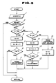
- Fig. 3 shows a vehicular height control routine which is also executed at a given timing, e.g. every 0.5 sec. It should be appreciated that, though the shown embodiment illustrates process for controlling vehicular height to maintain the vehicular height within the target height range by singular process and the following discussion will be given for height adjustment for one and general suspension system, the practical height adjusting or regulating operation will be performed with respect to respective front left, front right, rear left and rear right suspension systems 1FL, 1FR, 1RL and 1RR, independently of each other.
- vehicular height data H is derived on the basis of the vehicular height indicative signal value h (h FL , h FR , h RL , h RR ), at a step 2002. Thereafter, check is performed whether the status of the height regulating system is operating state for adjusting the height, at a step 2004. If height operating state as checked at the step 2004, process directly goes to END and return to the main program. On the other hand, if the status is not height adjusting state as checked at the step 2004, the vehicular height data H derived at the step 2002 is compared with the upper criterion H U defining the upper limit of the target height range, at a step 2006.
- an UP delay timer value t U which is periodically incremented while height adjustment for rising the vehicular height is performed, is cleared at a step 2008. Thereafter, a DOWN delay timer value t D which is periodically incremented while the height adjustment for lowering the vehicular height is performed, is incremented by one (1) at a step 2010.
- the UP delay timer and DOWN delay timer are provided for providing lag time between detection of the vehicular height out of the target height range to actual initiation of height adjustment so that height adjustment will never performed in response to temporary height variation out of the target height range.
- the DOWN lag timer value t D is compared with a DOWN lag time set value T D .
- the DOWN lag timer value t D is smaller than the DOWN lag time set value T D as checked at the step 2012, process directly goes END to return to the main program.
- the DOWN lad timer value t D is greater than or equal to the DOWN lag time set value T D , DOWN command is output from the microprocessor 26.
- the solenoid 10 of the corresponding pressure control valve 8 maintains the valve at open position and the solenoid 11 of the ventilation control valve 9 is energized to open the valve to expose the pnuematic circuit to the atmosphere to lower the pnuematic pressure in the pneumatic chamber 3 of the relevant suspension system 1.
- the vehicular height is lowered toward the height level defined by the upper criterion H U at a step 2014.
- the vehicular height data H as checked at the step 2006 is smaller than the upper threshold H U
- the vehicular height data H is compared with the lower threshold H L at a step 2016. If the vehicular height data H is smaller than the lower threshold H L , the DOWN lag timer value t D is cleared at a step 2018. Thereafter, the UP lag timer value t U is incremented by one (1) at a step 2020. The UP lag timer value t U is then compared with a UP lag time set value T U at a step 2022. When the UP lag timer value t U is smaller than the UP lag time set value T U , then process directly goes END.
- step 2016 When the vehicular height data H as checked at the step 2016 is greater than or equal to the lower threshold H L , then decision is made that height adjustment is not made at a step 2026, and the UP lag timer value t U and DOWN lag timer value t D are cleared at a step 2028. After step 2014, 2024 or 2028, process goes END to return to the main program.
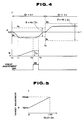
- Fig. 4 To further disclose the practical implementation of the process of height control to be performed by the preferred embodiment of the height regulating system, according to the present invention, example of practical control is given in Fig. 4. As seen from Fig. 4, it is assumed that steering operation to cause substantial level of lateral acceleration G y greater than the lateral acceleration threshold ⁇ y at a time t4. In such case, in a period from t0 to t4, the deadband adjusting value DZ is maintained at the normal value ⁇ 1. On the other hand, after the time t4, the deadband adjusting value DZ is changed to the value ⁇ 2.
- the UP lag timer is started to periodically increment the timer value.
- UP command is output to perform UP adjustment until the vehicular height H is recovered to be higher than or equal to the lower limit H L , at a time t3.
- the deadband adjusting value DZ is changed to the greater value ⁇ 2.
- the target height range defined by the upper limit H U and the lower limit H L is expanded. Therefore, as seen from Fig. 4, even when the vehicular height H is increased to be greater than the height level defined by the upper and lower limits in the normal mode, i.e. the period t0 to t4, height adjustment is not performed and thus allows vehicular attitude change.
- This technology is advantageously introduced so that the driver may easily recognize the critical condition of the vehicle.
- the shown embodiment varies the target height range between normal narrower range and broader range selected when the lateral longitudinal or vertical acceleration is greater than a predetermined criteria in stepwise fashion, it is possible to vary the target height range linearly in proportion to the lateral, longitudinal or vertical acceleration.
- the shown embodiment utilized the accelerations, i.e. lateral acceleration, longitudinal acceleration, vertical acceleration, as vehicular driving condition reflecting vehicular critical condition, it may be replaced with any other parameters which can represent the vehicular critical condition.
- the vehicular speed and the steering angular displacement or steering operation speed may be replacement of the lateral acceleration.
Landscapes
- Engineering & Computer Science (AREA)
- Mechanical Engineering (AREA)
- Vehicle Body Suspensions (AREA)
Applications Claiming Priority (2)
| Application Number | Priority Date | Filing Date | Title |
|---|---|---|---|
| JP62295874A JPH01136805A (ja) | 1987-11-24 | 1987-11-24 | 車高制御装置 |
| JP295874/87 | 1987-11-24 |
Publications (3)
| Publication Number | Publication Date |
|---|---|
| EP0318013A2 true EP0318013A2 (de) | 1989-05-31 |
| EP0318013A3 EP0318013A3 (en) | 1990-07-25 |
| EP0318013B1 EP0318013B1 (de) | 1993-08-11 |
Family
ID=17826295
Family Applications (1)
| Application Number | Title | Priority Date | Filing Date |
|---|---|---|---|
| EP88119612A Expired - Lifetime EP0318013B1 (de) | 1987-11-24 | 1988-11-24 | Höhenregelungssystem für Fahrzeuge mit vom Fahrverhalten abhängiger veränderlicher Sensivität |
Country Status (4)
| Country | Link |
|---|---|
| US (1) | US4948166A (de) |
| EP (1) | EP0318013B1 (de) |
| JP (1) | JPH01136805A (de) |
| DE (1) | DE3883170T2 (de) |
Cited By (9)
| Publication number | Priority date | Publication date | Assignee | Title |
|---|---|---|---|---|
| EP0672549A3 (de) * | 1994-03-14 | 1997-04-02 | Trw Inc | Verfahren und Vorrichtung für die Steuerung einer aktiven Radaufhängung. |
| EP0779167A3 (de) * | 1995-12-14 | 1998-04-08 | WABCO GmbH | Niveauregeleinrichtung |
| EP0925967A3 (de) * | 1997-12-26 | 2001-04-25 | Toyota Jidosha Kabushiki Kaisha | Vorrichtung zum Ermitteln eines Gefälles und zur Niveauregulierung eines Fahrzeugs und diese Vorrichtung benutzendes Verfahren |
| EP1484203A3 (de) * | 2003-06-05 | 2005-02-09 | Isuzu Motors Limited | Niveauregelung für Kraftfahrzeuge |
| EP1925471A1 (de) | 2006-11-22 | 2008-05-28 | WABCO GmbH | Verfahren zur Niveauregelung eines pneumatisch gefederten Fahrzeuges |
| WO2012163742A1 (de) * | 2011-05-27 | 2012-12-06 | Continental Teves Ag & Co. Ohg | Verfahren zur überwachung und steuerung eines pneumatischen niveauregelsystems eines fahrwerksystems |
| DE102015000718A1 (de) | 2015-01-21 | 2016-07-21 | Man Truck & Bus Ag | Verfahren und Vorrichtung zur Niveauregelung eines gefederten Fahrzeugaufbaus |
| DE102011100387B4 (de) * | 2011-05-04 | 2016-11-24 | Volkswagen Aktiengesellschaft | Verfahren und Vorrichtung zur Einstellung eines Fahrzeugniveaus |
| CN112874256A (zh) * | 2021-02-23 | 2021-06-01 | 湖南行必达网联科技有限公司 | 驾驶室高度调节方法及装置 |
Families Citing this family (25)
| Publication number | Priority date | Publication date | Assignee | Title |
|---|---|---|---|---|
| US5287277A (en) * | 1989-02-03 | 1994-02-15 | Fuji Jukogyo Kabushiki Kaisha | Method and apparatus for controlling height of a vehicle |
| JP2751391B2 (ja) * | 1989-05-12 | 1998-05-18 | トヨタ自動車株式会社 | 車高調整装置 |
| JPH0342318A (ja) * | 1989-07-06 | 1991-02-22 | Aisin Seiki Co Ltd | 車両におけるシヨツクアブソーバの減衰力制御装置 |
| DE68915442T2 (de) * | 1989-08-03 | 1995-01-05 | Nippon Denso Co | Kontrollsystem für die Dämpfkraft von Stossdämpfern. |
| DE69031794T2 (de) * | 1989-09-11 | 1998-04-23 | Denso Corp | Aufhängungssteuersystem |
| KR930010906B1 (ko) * | 1989-12-14 | 1993-11-17 | 니뽄 에어브레이크 가부시끼가이샤 | 유압 모터의 제어 회로 |
| JP2937405B2 (ja) * | 1990-04-24 | 1999-08-23 | マツダ株式会社 | 車両のサスペンション装置 |
| JPH04133811A (ja) * | 1990-09-27 | 1992-05-07 | Fuji Heavy Ind Ltd | 自動車用アクテイブサスペンションの制御方法 |
| GB2251412B (en) * | 1990-11-29 | 1995-05-10 | Fuji Heavy Ind Ltd | Method and system for controlling a vehicle suspension system |
| DE4129610A1 (de) * | 1991-09-06 | 1993-03-11 | Teves Gmbh Alfred | Niveauregelsystem fuer kraftfahrzeuge |
| US5430647A (en) * | 1992-12-07 | 1995-07-04 | Ford Motor Company | Method and apparatus for maintaining vehicular ride height |
| WO2005005178A2 (en) * | 2003-04-17 | 2005-01-20 | Bfs Diversified Products, Llc | Method and system for aligning a stationary vehicle with an artificial horizon |
| US8306696B2 (en) * | 2003-04-17 | 2012-11-06 | Driveright Holdings, Ltd. | Method and system for aligning a vehicle with an artificial horizon |
| US7267331B2 (en) * | 2003-06-23 | 2007-09-11 | Bfs Diversified Products, Llc | System and method for determining appropriate conditions for leveling a vehicle having an air suspension system |
| US7744099B2 (en) * | 2004-11-04 | 2010-06-29 | Driveright Holdings, Ltd. | Method and system for adjusting a vehicle aligned with an artificial horizon |
| US7461849B2 (en) * | 2005-12-22 | 2008-12-09 | Emiph, Llc | Method and apparatus for an electronic equipment rack |
| US8424885B2 (en) | 2005-12-22 | 2013-04-23 | Elliptical Mobile Solutions, LLC | Method and apparatus for an environmentally-protected electronic equipment enclosure |
| US7556271B2 (en) * | 2005-12-22 | 2009-07-07 | Emiph, Llc | Method and apparatus for an electronic equipment rack |
| US7611157B2 (en) * | 2005-12-22 | 2009-11-03 | Elliptical Mobile Solutions, LLC | Method and apparatus for an electronic equipment rack |
| US8155835B2 (en) * | 2008-02-21 | 2012-04-10 | Driveright Holdings, Ltd. | Vehicle chassis height adjustment method and system |
| GB2511827B (en) * | 2013-03-14 | 2015-08-12 | Jaguar Land Rover Ltd | Control unit for a vehicle suspension |
| US10017023B2 (en) | 2014-05-22 | 2018-07-10 | Wabco Gmbh | Method for controlling the level of an air-suspended motor vehicle |
| US11021031B2 (en) * | 2018-10-29 | 2021-06-01 | Polaris Industries Inc. | Suspension pre-load adjustment system |
| GB2597452B (en) | 2020-07-21 | 2023-05-17 | Jaguar Land Rover Ltd | Vehicle active suspension control system and method |
| US11912093B2 (en) * | 2021-07-06 | 2024-02-27 | DRiV Automotive Inc. | System and method for vehicle |
Family Cites Families (12)
| Publication number | Priority date | Publication date | Assignee | Title |
|---|---|---|---|---|
| JPS5758506A (en) * | 1980-09-27 | 1982-04-08 | Nissan Motor Co Ltd | Car height detecting device |
| JPS5813391A (ja) * | 1981-07-13 | 1983-01-25 | Res Assoc Petroleum Alternat Dev<Rapad> | 微生物固定化膜 |
| JPS58112817A (ja) * | 1981-12-25 | 1983-07-05 | Fuji Heavy Ind Ltd | 自動車用エアサスペンシヨンの車高制御方法 |
| US4527676A (en) * | 1982-02-13 | 1985-07-09 | Atsugi Motor Parts Co., Ltd. | Variable-damping-force shock absorber |
| US4526401A (en) * | 1982-11-30 | 1985-07-02 | Atsugi Motor Parts Co., Ltd. | Electronic control system for adjustable shock absorbers |
| US4660853A (en) * | 1984-02-21 | 1987-04-28 | Jephcott Edmund F N | Vehicle body tilting mechanism |
| JPS60183211A (ja) * | 1984-02-29 | 1985-09-18 | Nissan Motor Co Ltd | 車両用サスペンシヨン装置 |
| JPS6164517A (ja) * | 1984-09-06 | 1986-04-02 | Nissan Motor Co Ltd | 車両用サスペンシヨン装置 |
| JPS61166711A (ja) * | 1985-01-16 | 1986-07-28 | Toyota Motor Corp | サスペンシヨン制御装置 |
| JPS61275053A (ja) * | 1985-05-31 | 1986-12-05 | 財団法人鉄道総合技術研究所 | 車両の振動制御装置 |
| US4772547A (en) * | 1986-02-03 | 1988-09-20 | Hoffmann-La Roche Inc. | HTLV-III envelope peptides |
| JPS62184911A (ja) * | 1986-02-12 | 1987-08-13 | Nissan Motor Co Ltd | 車高制御装置 |
-
1987
- 1987-11-24 JP JP62295874A patent/JPH01136805A/ja active Pending
-
1988
- 1988-11-24 EP EP88119612A patent/EP0318013B1/de not_active Expired - Lifetime
- 1988-11-24 DE DE88119612T patent/DE3883170T2/de not_active Expired - Fee Related
- 1988-11-25 US US07/275,985 patent/US4948166A/en not_active Expired - Fee Related
Cited By (13)
| Publication number | Priority date | Publication date | Assignee | Title |
|---|---|---|---|---|
| EP0672549A3 (de) * | 1994-03-14 | 1997-04-02 | Trw Inc | Verfahren und Vorrichtung für die Steuerung einer aktiven Radaufhängung. |
| EP0779167A3 (de) * | 1995-12-14 | 1998-04-08 | WABCO GmbH | Niveauregeleinrichtung |
| EP0925967A3 (de) * | 1997-12-26 | 2001-04-25 | Toyota Jidosha Kabushiki Kaisha | Vorrichtung zum Ermitteln eines Gefälles und zur Niveauregulierung eines Fahrzeugs und diese Vorrichtung benutzendes Verfahren |
| EP1484203A3 (de) * | 2003-06-05 | 2005-02-09 | Isuzu Motors Limited | Niveauregelung für Kraftfahrzeuge |
| US6983201B2 (en) | 2003-06-05 | 2006-01-03 | Isuzu Motors Limited | Vehicle height adjustment system |
| EP1925471A1 (de) | 2006-11-22 | 2008-05-28 | WABCO GmbH | Verfahren zur Niveauregelung eines pneumatisch gefederten Fahrzeuges |
| DE102011100387B4 (de) * | 2011-05-04 | 2016-11-24 | Volkswagen Aktiengesellschaft | Verfahren und Vorrichtung zur Einstellung eines Fahrzeugniveaus |
| WO2012163742A1 (de) * | 2011-05-27 | 2012-12-06 | Continental Teves Ag & Co. Ohg | Verfahren zur überwachung und steuerung eines pneumatischen niveauregelsystems eines fahrwerksystems |
| US9259987B2 (en) | 2011-05-27 | 2016-02-16 | Continental Teves Ag & Co. Ohg | Method for monitoring and controlling a pneumatic ride-height control system of a chassis system |
| DE102015000718A1 (de) | 2015-01-21 | 2016-07-21 | Man Truck & Bus Ag | Verfahren und Vorrichtung zur Niveauregelung eines gefederten Fahrzeugaufbaus |
| EP3047987A2 (de) | 2015-01-21 | 2016-07-27 | MAN Truck & Bus AG | Verfahren und vorrichtung zur niveauregelung eines gefederten fahrzeugaufbaus |
| CN112874256A (zh) * | 2021-02-23 | 2021-06-01 | 湖南行必达网联科技有限公司 | 驾驶室高度调节方法及装置 |
| CN112874256B (zh) * | 2021-02-23 | 2022-08-16 | 湖南行必达网联科技有限公司 | 驾驶室高度调节方法及装置 |
Also Published As
| Publication number | Publication date |
|---|---|
| EP0318013A3 (en) | 1990-07-25 |
| DE3883170D1 (de) | 1993-09-16 |
| EP0318013B1 (de) | 1993-08-11 |
| JPH01136805A (ja) | 1989-05-30 |
| DE3883170T2 (de) | 1994-03-17 |
| US4948166A (en) | 1990-08-14 |
Similar Documents
| Publication | Publication Date | Title |
|---|---|---|
| EP0318013B1 (de) | Höhenregelungssystem für Fahrzeuge mit vom Fahrverhalten abhängiger veränderlicher Sensivität | |
| US4936604A (en) | Vehicular height control system for automotive suspension system with improved height control characteristics on undulated road and/or rough road | |
| EP0306004B1 (de) | Elektronisch geregeltes Fluidumaufhängungssystem | |
| US5037128A (en) | Active suspension system with enhanced stability | |
| EP0306003B1 (de) | Elektronisch geregeltes Fluidumaufhängungssystem für die Neigungsregelung um die Längs- und Querachse einer Fahrzeugkarosserie | |
| EP0306819B1 (de) | Elektronisch geregeltes Fluidumaufhängungssystem mit vorausberechneter und rückgekoppelter Regelung der Fahrzeuglage | |
| EP0415423B1 (de) | Radaufhängungs-Regelsystem mit variabler Lenkcharakteristik | |
| US5159554A (en) | Electronic controlled fluid suspension system | |
| US5085458A (en) | Attitude change suppression control system for active suspension system with high sensitivity of vehicular attitude change | |
| US5141245A (en) | Apparatus for adjusting vehicle body height | |
| EP0326180B1 (de) | Aktiv geregeltes Aufhängungssystem mit Ausgleich für Phasenverzögerung im Regelungssystem | |
| US4905152A (en) | Actively controlled suspension system with control characteristics variable depending upon vehicular speed | |
| EP0345816B1 (de) | Antirollregelung für aktiv geregelte Fahrzeugaufhängungssysteme mit erhöhter Fähigkeit zur Ermittlung der Rollneigung | |
| US5180024A (en) | Vehicle height control apparatus | |
| EP0313030A2 (de) | Höhenregelungssystem in einer Kraftfahrzeugaufhängung für eine Regelung der Höhe und der Neigungsunterdrückung mit hohem Ansprechverhalten für die Regelung der Höhe | |
| EP0318721A1 (de) | Aktiv geregeltes Aufhängungssystem mit Regelung der Stromversorgung | |
| EP0364965B1 (de) | Aktive Radaufhängung für ein Kraftfahrzeug mit Driftwinkel-abhängiger Steuerung zur Verbesserung des Lenkverhaltens | |
| US4856798A (en) | Electronically controlled fluid suspension system | |
| US4869528A (en) | Electronically controlled fluid suspension system | |
| EP0416560B1 (de) | Aufhängungssteueranlage mit einer von Fahrbedingungen abhängigen Niveauregelung | |
| JPS6092913A (ja) | 車高制御装置 | |
| US5173857A (en) | Automotive suspension system with feature of prevention of sudden change of vehicular attitude at vehicular attitude influencing acceleration beyond critical magnitude | |
| JPH07215035A (ja) | サスペンション制御装置 | |
| EP0415424B1 (de) | Aktives Radaufhängungssystem mit verbesserter Aufhängungsregelcharakteristik beim Ein-Aus-Übergang der Aufhängungsregelung | |
| US5131676A (en) | Suspension control system with monitoring of inertia force with high precision |
Legal Events
| Date | Code | Title | Description |
|---|---|---|---|
| PUAI | Public reference made under article 153(3) epc to a published international application that has entered the european phase |
Free format text: ORIGINAL CODE: 0009012 |
|
| 17P | Request for examination filed |
Effective date: 19881124 |
|
| AK | Designated contracting states |
Kind code of ref document: A2 Designated state(s): DE GB |
|
| PUAL | Search report despatched |
Free format text: ORIGINAL CODE: 0009013 |
|
| AK | Designated contracting states |
Kind code of ref document: A3 Designated state(s): DE GB |
|
| 17Q | First examination report despatched |
Effective date: 19911128 |
|
| GRAA | (expected) grant |
Free format text: ORIGINAL CODE: 0009210 |
|
| AK | Designated contracting states |
Kind code of ref document: B1 Designated state(s): DE GB |
|
| REF | Corresponds to: |
Ref document number: 3883170 Country of ref document: DE Date of ref document: 19930916 |
|
| PLBE | No opposition filed within time limit |
Free format text: ORIGINAL CODE: 0009261 |
|
| STAA | Information on the status of an ep patent application or granted ep patent |
Free format text: STATUS: NO OPPOSITION FILED WITHIN TIME LIMIT |
|
| 26N | No opposition filed | ||
| PGFP | Annual fee paid to national office [announced via postgrant information from national office to epo] |
Ref country code: GB Payment date: 19951115 Year of fee payment: 8 |
|
| PGFP | Annual fee paid to national office [announced via postgrant information from national office to epo] |
Ref country code: DE Payment date: 19951128 Year of fee payment: 8 |
|
| PG25 | Lapsed in a contracting state [announced via postgrant information from national office to epo] |
Ref country code: GB Effective date: 19961124 |
|
| GBPC | Gb: european patent ceased through non-payment of renewal fee |
Effective date: 19961124 |
|
| PG25 | Lapsed in a contracting state [announced via postgrant information from national office to epo] |
Ref country code: DE Effective date: 19970801 |