EP0317652A1 - Suction device for yarnthreading - Google Patents
Suction device for yarnthreading Download PDFInfo
- Publication number
- EP0317652A1 EP0317652A1 EP87117234A EP87117234A EP0317652A1 EP 0317652 A1 EP0317652 A1 EP 0317652A1 EP 87117234 A EP87117234 A EP 87117234A EP 87117234 A EP87117234 A EP 87117234A EP 0317652 A1 EP0317652 A1 EP 0317652A1
- Authority
- EP
- European Patent Office
- Prior art keywords
- pressurized liquid
- yarn
- jets
- hole
- suction device
- Prior art date
- Legal status (The legal status is an assumption and is not a legal conclusion. Google has not performed a legal analysis and makes no representation as to the accuracy of the status listed.)
- Granted
Links
- 239000007788 liquid Substances 0.000 claims abstract description 52
- 238000002347 injection Methods 0.000 claims abstract description 51
- 239000007924 injection Substances 0.000 claims abstract description 51
- XLYOFNOQVPJJNP-UHFFFAOYSA-N water Substances O XLYOFNOQVPJJNP-UHFFFAOYSA-N 0.000 abstract description 66
- 238000004804 winding Methods 0.000 description 5
- 238000010586 diagram Methods 0.000 description 4
- 238000005259 measurement Methods 0.000 description 3
- 239000004677 Nylon Substances 0.000 description 2
- 239000012530 fluid Substances 0.000 description 2
- 229920001778 nylon Polymers 0.000 description 2
- 238000009987 spinning Methods 0.000 description 2
- 239000002699 waste material Substances 0.000 description 2
- 230000003247 decreasing effect Effects 0.000 description 1
- 239000000203 mixture Substances 0.000 description 1
- -1 polyethylene terephthalate Polymers 0.000 description 1
- 229920000139 polyethylene terephthalate Polymers 0.000 description 1
- 239000005020 polyethylene terephthalate Substances 0.000 description 1
- 238000007789 sealing Methods 0.000 description 1
- 238000011144 upstream manufacturing Methods 0.000 description 1
Images


Classifications
-
- B—PERFORMING OPERATIONS; TRANSPORTING
- B65—CONVEYING; PACKING; STORING; HANDLING THIN OR FILAMENTARY MATERIAL
- B65H—HANDLING THIN OR FILAMENTARY MATERIAL, e.g. SHEETS, WEBS, CABLES
- B65H51/00—Forwarding filamentary material
- B65H51/16—Devices for entraining material by flow of liquids or gases, e.g. air-blast devices
-
- B—PERFORMING OPERATIONS; TRANSPORTING
- B65—CONVEYING; PACKING; STORING; HANDLING THIN OR FILAMENTARY MATERIAL
- B65H—HANDLING THIN OR FILAMENTARY MATERIAL, e.g. SHEETS, WEBS, CABLES
- B65H54/00—Winding, coiling, or depositing filamentary material
- B65H54/86—Arrangements for taking-up waste material before or after winding or depositing
- B65H54/88—Arrangements for taking-up waste material before or after winding or depositing by means of pneumatic arrangements, e.g. suction guns
-
- B—PERFORMING OPERATIONS; TRANSPORTING
- B65—CONVEYING; PACKING; STORING; HANDLING THIN OR FILAMENTARY MATERIAL
- B65H—HANDLING THIN OR FILAMENTARY MATERIAL, e.g. SHEETS, WEBS, CABLES
- B65H2701/00—Handled material; Storage means
- B65H2701/30—Handled filamentary material
- B65H2701/31—Textiles threads or artificial strands of filaments
Definitions
- the present invention relates to a suction device (hereinafter also referred to as "suction gun") for drawing and holding a yarn by pressurized liquid such as pressurized water, thereby to thread the yarn to a desired position.
- suction gun for drawing and holding a yarn by pressurized liquid such as pressurized water, thereby to thread the yarn to a desired position.
- a movable suction gun for drawing and holding a running yarn is employed in order to thread the yarn to a desired apparatus such as a godet roller, a bobbin of a winder or a yarn guide.
- a suction gun pressurized air or pressurized liquid is employed as actuating fluid for drawing the yarn.
- a preferable type of suction gun employing pressurized water as actuating fluid is disclosed in U.S. Patent No. 4,666,590, which comprises first and second injection nozzles (suction nozzles).
- the first injection nozzle is provided oppositely to an inlet port of a pressurized liquid exhaust pipe, so that the yarn is thrusted into the interior of the pressurized liquid exhaust pipe (yarn guide pipe) by injection force of the pressurized water injected from the first injection nozzle.
- An internal space of the pressurized liquid exhaust pipe defines a pressurized liquid exhaust passage.
- the second injection nozzle is provided in the upstream portion of the pressurized liquid exhaust passage, to obliquely inject pressurized water into the pressurized liquid exhaust passage.
- the yarn in the pressurized liquid exhaust passage is sucked and drawn by injection force of the pressurized water from the second injection nozzle, to be discharged from the suction gun with the pressurized water.
- an injection nozzle having a plurality of jets is employed as the second injection nozzle.
- the plurality of jets are so directed that axes thereof intersect with each other at a single point on the axis of a through hole forming a part of the pressurized liquid exhaust passage, which is identical to an axis of the first injection nozzle. Therefore, the pressurized water introduced into the pressurized liquid exhaust pipe by the first injection nozzle is subjected to interference by the pressurized water from the second injection nozzle, and a yarn sucking force or tension in suction gun is remarkably weakened. As the result, a large amount of pressurized water must be supplied in order to apply sufficient suction force to the yarn, whereby the cost required for water supply is increased.
- An object of the present invention is to provide a suction device for yarn-threading which can apply sufficient tension in suction to a yarn without requiring a large amount of pressurized liquid.
- a suction device for yarn-threading comprises a first injection nozzle having a first jet for injecting first pressurized liquid; a pressurized liquid exhaust pipe having an inlet port facing the first jet with a predetermined yarn introducing space and defining a pressurized liquid exhaust passage by internal space of the pressurized liquid exhaust pipe, the pressurized liquid exhaust passage including a through hole; and a second injection nozzle having a plurality of second jets around the through hole for obliquely injecting second pressurized liquid into the pressurized liquid exhaust passage; and respective axes of the second jets intersect with each other at an intersection point displaced by a predetermined distance from an axis of the through hole.
- the predetermined distance has a value within a range of from 0.2mm to 0.9mm.
- injection force of the first pressurized liquid injected from the first injection nozzle does not interfere with that of the second pressurized liquid injected from the second injection nozzle, whereby suction force for the yarn is effectively increased.
- the amount of pressurized liquid required for obtaining prescribed suction force or yarn tension in suction can be reduced.
- Fig. 1 is an explanatory diagram illustrating a yarn-threading operation employing a suction gun 1.
- the suction gun 1 is employed in order to thread a synthetic yarn Y to a rotating bobbin 105, for example.
- the yarn Y extruded through spinning holes of spinnerets (not shown) provided in the lower portion of a spinning block 101 is derived from a plurality of ducts 102.
- the yarn Y running at a high speed is supplied to yarn winding device 106 through godet rollers 103.
- a plurality of such winding devices 106 are provided in correspondence to each of the ducts 102, and each of the winding device 106 has a winder 104 and a bobbin 105 mounted on the same to rotate with a spindle (not shown) of the winder 104.
- pressurized water W is supplied to the suction gun 1 from a water pressurizing pump 109 through a hose 110.
- the suction gun 1 is moved toward the bobbin 105 while picking-up and pulling the running yarn Y with suction force induced by an injection of the pressurized water W, the yarn Y captured by the suction gun 1 is caught and wound on the rotating bobbin 105.
- yarn-threading operation is completed with respect to the first bobbin 105.
- Water discharged from the suction gun 1 and waste yarn are discharged to a waste yarn disposal device 108 through a hose 111.
- the suction gun 1 In order to perform yarn-threading operation of another yarn Y to another winding device 106, the suction gun 1 is manually moved to perform operation similar to the above.
- the suction gun 1 of this embodiment is a suction device which employs pressurized water as pressurized liquid.
- Details of the yarn disposal device 108 are disclosed in U.S. Patent No. 4,666,590, for example.
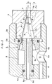
- Fig. 2 is a partially fragmented sectional view of the suction gun 1
- Fig. 3 is a partially enlarged view thereof.
- the suction gun 1 comprises a substantially straight-tubular gun body 1a and a pressurized water introducing pipe 1b extending from a side wall of the gun body 1a.
- the pressurized water introducing pipe 1b receives the pressurized water W supplied from the hose 110 of Fig. 1 from a pressurized water inlet port 9 provided in an end thereof.
- a valve 10 is provided in a part of the pressurized water introducing pipe 1b, to be opened/closed by operation of a valve handle 10a.
- the other end of the pressurized water introducing pipe 1b is fixed to the side wall of the gun body 1a.
- the pressurized water W is introduced into the interior of the gun body 1a through a pressurized water inlet hole 15, being circular in section, which is provided on the side wall of the gun body 1a.
- a part of the pressurized water W (first pressurized water) is guided toward the forward end of the gun body 1a through a pressurized water feed path 13 which is provided in the interior of the body 1a.
- a first injection nozzle 2 having a first yet 2a is mounted on the forward end of the body 1a.
- the pressurized water W is fed to the first injection nozzle 2, to be injected from the first jet 2a rightwardly in Fig. 2.
- the pressurized liquid exhaust pipe 3 is formed by sequentially screwing first to third tubular members 3a to 3c.
- a pressurized liquid exhaust passage 20 is defined and formed by an internal space of the pressurized liquid exhaust pipe 3, to substantially linearly extend from an end of the pressurized liquid exhaust pipe 3 to the other end thereof.
- An inlet port 4a of the first tublar member 3a is positioned to face the first jet 2a with a yarn introducing space 21.
- the pressurized liquid from the first jet 2a is injected into the pressurized liquid exhaust passage 20.
- This pressurized liquid exhaust passage 20 is formed by respective internal passages 5a, 7 and 5b of the first to third tubular members 3a to 3c and a through hole 6d formed in a second injection nozzle 6 as hereinafter described.
- the suction gun 1 In yarn-threading operation, the suction gun 1 is manually moved to introduce the yarn Y into a yarn introducing space 21.
- the yarn Y is thrusted into the pressurized liquid exhaust passage 20 with the pressurized water injected from the first jet 2a by injection force of the pressurized water, whereby the suction gun 1 captures the yarn Y.
- the pressurized water and the yarn Y pass through the pressurized liquid exhaust passage 20, to be discharged through an outlet port 4b into the hose 111 shown in Fig. 1.
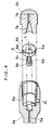
- the second injection nozzle 6 is assembled in a predetermined position of the pressurized liquid exhaust passage 20.
- the second injection nozzle 6 has a shank 6c, a nozzle portion 6b and a sealing part 6e, all of which are integrated with each other.
- the nozzle portion 6b four second jets 6a are formed.
- the through hole 6d is formed through the seeling part 6e, the shank 6c and the nozzle portion 6b.
- the second jets 6a are positioned to surround the through hole 6d.
- the sectional shape of the through hole 6d is arbitrary, it is preferred to be a circle.
- an axis L of the through hole 6d has an important meaning in the embodiment, and it is defined by a line passisng through the central point of the circle, when the sectional shape is the circle.
- the axis L is defined by a line passing through a point at which a major axis and a minor axis defined on a plane including the ellipse are crossing each other.
- the axis L is defined by a line passsing through a point at which each of diagonal lines of the polygon are crossing each other.
- an internal space 8a which opens to the internal passage 5a is defined in the interior of the first tubular member 3a.
- the diameter of the internal space 8a is larger than that of the shank 6c and substantially identical to the diameter of the nozzle portion 6b.
- an annular pressurized water chamber 8 shown in Fig. 3 is formed by inserting the second injection nozzle 6 into the internal space 8a.
- the pressurized water chamber 8 opens to the pressurized water inlet hole 15. Therefore, within the pressurized water externally supplied through the pressurized water inlet hole 15, a part (second pressurized water) not being supplied to the first injection nozzle 2 flows into the pressurized water chamber 8.
- the pressurized water in the pressurized water chamber 8 is obliquely injected into an internal passage 7 through the second jets 6a.
- the internal passage 7 is formed by combination of a truncated-conical injection chamber 7a existing in the vicinity of opening positions of the second jets 6a and a tubular passage 7b extending from the injection chamber 7a.
- the direction of the second jets 6a is so determined that axes A1 to A4 thereof (Fig. 2 shows only A1 and A2) intersect with each other at an intersection point P, which is located in a position displaced by a prescribed distance (hereinafter referred to as "offset distance") E from an axis L of the through hole 6d.
- the intersection point P is given in the internal passage 7, and preferably, it is given in the tublar passage 7b.
- the first jet 2a; the internal passage 5a, 7 and 5b forming the pressurized liquid exhaust passage 20; and the through hole 6d are coaxial with each other. At least, it is preferred that the axis of the first jet 2a coincides with the axis L of the through hole 6d.
- the inclining angle ⁇ of the axes A1 to A4 of the second jets 6a from the line A may be arbitrary decided.
- the inclining angle ⁇ is 3° to 20°, and most preferably, it is 5° to 15°.
- the diameter of the pressurized liquid exhaust passage 20 may be decided in response to the sectional size of the yarn Y to be threaded. It is preferable that the diameters of the internal passage 5a and the through hole 6d are selected in the range of from 1.5 to 8.0mm, that of the tubular passage 7b is from 2.0 to 15.0mm, and that of the tubular passage 5b is from 2.5 to 20.0mm.
- Fig. 3 corresponds to a sectional view taken along the line III - III in Fig. 5.
- Fig. 6 shows such circumstances as a partially enlarged sectional view taken along the line VI - VI in Fig. 3.
- the intersection point P is located in the tubular passage 7b.
- pressurized water is injected along the axes A1 to A4 of the second jets 6a, the pressurized water flows into the tubular passage 7b toward the intersection point P.
- the intersection point P is set in the position displaced by the offset distance E from the axis L of the through hole 6d, whereby the first pressurized water introduced into the pressurized liquid exhaust passage 20 with the yarn Y by the first injection nozzle 2 which is coaxial to the through hole 6d is not subjected to interference by the second pressurized water from the second injection nozzle 6. Therefore, force of the second pressurized water from the second injection nozzle 6 is superposed on force of the first pressurized water from the first injection nozzle 2 in the tubular passage 7b, whereby the suction force applied to the yarn Y is remarkably increased.
- the pressurized water sufficiently fills up the tubular passage 7b, and the yarn Y smoothly flows through the tubular passage 7b and the internal passage 5b (Fig. 2) by the pressurized water to obtain larger suction force.
- Fig. 7 shows the result of measurement of this case as relation between the offset distance E and yarn suction force (tension suction) T(gram).
- the straight line A is at the same angle ⁇ with respect to the axes A1 to A4 and the second jets 6a are arranged at isometric angle intervals, such a condition gives uniform tension to the yarn Y.
- the intersection point of the axes of the respective jets included in the second injection nozzle is displaced by a predetermined distance from the axis of the through hole in the pressurized liquid exhaust pipe, thereby to avoid interference between the pressurized liquid introduced into the exhaust pipe by the first injection nozzle and that introduced by the second injection nozzle in an intermediate portion of the exhaust passage.
- force of the pressurized liquid from the second injection nozzle is superposed on the force of the pressurized liquid introduced by the first injectionn nozzle. Consequently, suction force applied to the yarn can be extremely increased without increasing the amount of supply of the pressurized liquid.
Landscapes
- Spinning Methods And Devices For Manufacturing Artificial Fibers (AREA)
Abstract

Description
- The present invention relates to a suction device (hereinafter also referred to as "suction gun") for drawing and holding a yarn by pressurized liquid such as pressurized water, thereby to thread the yarn to a desired position.
- It is well known in the art that a movable suction gun for drawing and holding a running yarn is employed in order to thread the yarn to a desired apparatus such as a godet roller, a bobbin of a winder or a yarn guide. In such a suction gun, pressurized air or pressurized liquid is employed as actuating fluid for drawing the yarn.
- A preferable type of suction gun employing pressurized water as actuating fluid is disclosed in U.S. Patent No. 4,666,590, which comprises first and second injection nozzles (suction nozzles). The first injection nozzle is provided oppositely to an inlet port of a pressurized liquid exhaust pipe, so that the yarn is thrusted into the interior of the pressurized liquid exhaust pipe (yarn guide pipe) by injection force of the pressurized water injected from the first injection nozzle. An internal space of the pressurized liquid exhaust pipe defines a pressurized liquid exhaust passage. The second injection nozzle is provided in the upstream portion of the pressurized liquid exhaust passage, to obliquely inject pressurized water into the pressurized liquid exhaust passage. The yarn in the pressurized liquid exhaust passage is sucked and drawn by injection force of the pressurized water from the second injection nozzle, to be discharged from the suction gun with the pressurized water.
- In such a two-stage injection type suction gun, an injection nozzle having a plurality of jets is employed as the second injection nozzle. In a prior art, the plurality of jets are so directed that axes thereof intersect with each other at a single point on the axis of a through hole forming a part of the pressurized liquid exhaust passage, which is identical to an axis of the first injection nozzle. Therefore, the pressurized water introduced into the pressurized liquid exhaust pipe by the first injection nozzle is subjected to interference by the pressurized water from the second injection nozzle, and a yarn sucking force or tension in suction gun is remarkably weakened. As the result, a large amount of pressurized water must be supplied in order to apply sufficient suction force to the yarn, whereby the cost required for water supply is increased.
- An object of the present invention is to provide a suction device for yarn-threading which can apply sufficient tension in suction to a yarn without requiring a large amount of pressurized liquid.
- According to the present invention, a suction device for yarn-threading comprises a first injection nozzle having a first jet for injecting first pressurized liquid; a pressurized liquid exhaust pipe having an inlet port facing the first jet with a predetermined yarn introducing space and defining a pressurized liquid exhaust passage by internal space of the pressurized liquid exhaust pipe, the pressurized liquid exhaust passage including a through hole; and a second injection nozzle having a plurality of second jets around the through hole for obliquely injecting second pressurized liquid into the pressurized liquid exhaust passage; and respective axes of the second jets intersect with each other at an intersection point displaced by a predetermined distance from an axis of the through hole.
- According to a preferred embodiment of the present invention, the predetermined distance has a value within a range of from 0.2mm to 0.9mm.
- According to the present invention, injection force of the first pressurized liquid injected from the first injection nozzle does not interfere with that of the second pressurized liquid injected from the second injection nozzle, whereby suction force for the yarn is effectively increased. In other words, the amount of pressurized liquid required for obtaining prescribed suction force or yarn tension in suction can be reduced.
- These and other objects, features, aspects and advantages of the present invention will become more apparent from the following detailed description of the present invention when taken in conjunction with the accompanying drawings.
-
- Fig. 1 is a diagram for illustrating the situation of applying a suction gun in yarn-threading;
- Fig. 2 is a partially fragmented sectional view showing a suction gun according to a preferred embodiment of the present invention;
- Fig. 3 is a partially enlarged view of the suction gun shown in Fig. 2;
- Fig. 4 is a diagram showing a positional relation between a second injection nozzle and a pressurized water chamber;
- Figs 5 and 6 are sectional end views taken along lines V - V and VI - VI in Fig. 3, respectively;
- Fig. 7 is a graph showing the result of an experiment in first embodiment; and
- Fig. 8 is a diagram showing a second injection nozzle employed in third embodiment.
- Fig. 1 is an explanatory diagram illustrating a yarn-threading operation employing a
suction gun 1. Before explaining internal structure of thesuction gun 1 according to an embodiment of the present invention, description is made on the situation in which thesuction gun 1 is employed in the yarn-threading operation with reference to Fig. 1. - The
suction gun 1 is employed in order to thread a synthetic yarn Y to a rotatingbobbin 105, for example. The yarn Y extruded through spinning holes of spinnerets (not shown) provided in the lower portion of aspinning block 101 is derived from a plurality ofducts 102. The yarn Y running at a high speed is supplied toyarn winding device 106 throughgodet rollers 103. A plurality of suchwinding devices 106 are provided in correspondence to each of theducts 102, and each of thewinding device 106 has a winder 104 and abobbin 105 mounted on the same to rotate with a spindle (not shown) of thewinder 104. - In order to thread one of the yarns Y to the
corresponding winding device 106, pressurized water W is supplied to thesuction gun 1 from awater pressurizing pump 109 through ahose 110. When thesuction gun 1 is moved toward thebobbin 105 while picking-up and pulling the running yarn Y with suction force induced by an injection of the pressurized water W, the yarn Y captured by thesuction gun 1 is caught and wound on the rotatingbobbin 105. Thus, yarn-threading operation is completed with respect to thefirst bobbin 105. Water discharged from thesuction gun 1 and waste yarn are discharged to a wasteyarn disposal device 108 through ahose 111. - In order to perform yarn-threading operation of another yarn Y to another
winding device 106, thesuction gun 1 is manually moved to perform operation similar to the above. - Namely, the
suction gun 1 of this embodiment is a suction device which employs pressurized water as pressurized liquid. Details of theyarn disposal device 108 are disclosed in U.S. Patent No. 4,666,590, for example. - Fig. 2 is a partially fragmented sectional view of the
suction gun 1, and Fig. 3 is a partially enlarged view thereof. Thesuction gun 1 comprises a substantially straight-tubular gun body 1a and a pressurizedwater introducing pipe 1b extending from a side wall of the gun body 1a. The pressurizedwater introducing pipe 1b receives the pressurized water W supplied from thehose 110 of Fig. 1 from a pressurizedwater inlet port 9 provided in an end thereof. Avalve 10 is provided in a part of the pressurizedwater introducing pipe 1b, to be opened/closed by operation of avalve handle 10a. - The other end of the pressurized
water introducing pipe 1b is fixed to the side wall of the gun body 1a. The pressurized water W is introduced into the interior of the gun body 1a through a pressurizedwater inlet hole 15, being circular in section, which is provided on the side wall of the gun body 1a. A part of the pressurized water W (first pressurized water) is guided toward the forward end of the gun body 1a through a pressurizedwater feed path 13 which is provided in the interior of the body 1a. Afirst injection nozzle 2 having a first yet 2a is mounted on the forward end of the body 1a. The pressurized water W is fed to thefirst injection nozzle 2, to be injected from thefirst jet 2a rightwardly in Fig. 2. - Most part of the body 1a is formed by a pressurized
liquid exhaust pipe 3 yarn guide pipe. The pressurizedliquid exhaust pipe 3 is formed by sequentially screwing first to thirdtubular members 3a to 3c. A pressurizedliquid exhaust passage 20 is defined and formed by an internal space of the pressurizedliquid exhaust pipe 3, to substantially linearly extend from an end of the pressurizedliquid exhaust pipe 3 to the other end thereof. - An
inlet port 4a of thefirst tublar member 3a is positioned to face thefirst jet 2a with ayarn introducing space 21. Thus, the pressurized liquid from thefirst jet 2a is injected into the pressurizedliquid exhaust passage 20. This pressurizedliquid exhaust passage 20 is formed by respectiveinternal passages tubular members 3a to 3c and a throughhole 6d formed in asecond injection nozzle 6 as hereinafter described. - In yarn-threading operation, the
suction gun 1 is manually moved to introduce the yarn Y into ayarn introducing space 21. The yarn Y is thrusted into the pressurizedliquid exhaust passage 20 with the pressurized water injected from thefirst jet 2a by injection force of the pressurized water, whereby thesuction gun 1 captures the yarn Y. The pressurized water and the yarn Y pass through the pressurizedliquid exhaust passage 20, to be discharged through anoutlet port 4b into thehose 111 shown in Fig. 1. - The
second injection nozzle 6 is assembled in a predetermined position of the pressurizedliquid exhaust passage 20. As shown in Fig. 4, thesecond injection nozzle 6 has ashank 6c, anozzle portion 6b and asealing part 6e, all of which are integrated with each other. In thenozzle portion 6b, foursecond jets 6a are formed. The throughhole 6d is formed through the seelingpart 6e, theshank 6c and thenozzle portion 6b. Thesecond jets 6a are positioned to surround the throughhole 6d. Although the sectional shape of the throughhole 6d is arbitrary, it is preferred to be a circle. As hereinafter described, an axis L of the throughhole 6d has an important meaning in the embodiment, and it is defined by a line passisng through the central point of the circle, when the sectional shape is the circle. When the sectional shape is an ellipse, the axis L is defined by a line passing through a point at which a major axis and a minor axis defined on a plane including the ellipse are crossing each other. Further, when a polygon is employed as the sectional shape, the axis L is defined by a line passsing through a point at which each of diagonal lines of the polygon are crossing each other. - As shown in Fig. 4, an
internal space 8a which opens to theinternal passage 5a is defined in the interior of the firsttubular member 3a. The diameter of theinternal space 8a is larger than that of theshank 6c and substantially identical to the diameter of thenozzle portion 6b. Thus, an annularpressurized water chamber 8 shown in Fig. 3 is formed by inserting thesecond injection nozzle 6 into theinternal space 8a. Thepressurized water chamber 8 opens to the pressurizedwater inlet hole 15. Therefore, within the pressurized water externally supplied through the pressurizedwater inlet hole 15, a part (second pressurized water) not being supplied to thefirst injection nozzle 2 flows into thepressurized water chamber 8. The pressurized water in thepressurized water chamber 8 is obliquely injected into aninternal passage 7 through thesecond jets 6a. Theinternal passage 7 is formed by combination of a truncated-conical injection chamber 7a existing in the vicinity of opening positions of thesecond jets 6a and atubular passage 7b extending from theinjection chamber 7a. By injection force of the pressurized water injected from thesecond jets 6a, further tension in suction is applied to the yarn Y in a direction toward theoutlet port 4b shown in Fig. 2. Thus, larger suction force acts on the yarn Y. The pressurized water injected from thesecond jets 6a is also discharged from theoutlet port 4b. - Description is now made on the direction of arrangement of the
second jets 6a corresponding to the feature of the present invention. The direction of thesecond jets 6a is so determined that axes A₁ to A₄ thereof (Fig. 2 shows only A₁ and A₂) intersect with each other at an intersection point P, which is located in a position displaced by a prescribed distance (hereinafter referred to as "offset distance") E from an axis L of the throughhole 6d. The intersection point P is given in theinternal passage 7, and preferably, it is given in thetublar passage 7b. In this embodiment, thefirst jet 2a; theinternal passage liquid exhaust passage 20; and the throughhole 6d are coaxial with each other. At least, it is preferred that the axis of thefirst jet 2a coincides with the axis L of the throughhole 6d. - Assuming that symbol A represents a straight line passsing through the intersection point P and being parallel to the axis L of the through
hole 6d, the straight line A is at the same angle ϑ with respect to the axes A₁ to A₄. - The inclining angle ϑ of the axes A₁ to A₄ of the
second jets 6a from the line A (accordingly, from the axis L) may be arbitrary decided. Preferably, the inclining angle ϑ is 3° to 20°, and most preferably, it is 5° to 15°. The diameter of the pressurizedliquid exhaust passage 20 may be decided in response to the sectional size of the yarn Y to be threaded. It is preferable that the diameters of theinternal passage 5a and the throughhole 6d are selected in the range of from 1.5 to 8.0mm, that of thetubular passage 7b is from 2.0 to 15.0mm, and that of thetubular passage 5b is from 2.5 to 20.0mm. - Fig. 5 is a sectional end view taken along the line V -V in Fig. 3, in which respective opening portions of the
second jets 6a are arranged at isometric intervals (360 ÷ 4 = 90° in this embodiment) about the straight line A. Fig. 3 corresponds to a sectional view taken along the line III - III in Fig. 5. - Fig. 6 shows such circumstances as a partially enlarged sectional view taken along the line VI - VI in Fig. 3. As hereinabove described, the intersection point P is located in the
tubular passage 7b. When pressurized water is injected along the axes A₁ to A₄ of thesecond jets 6a, the pressurized water flows into thetubular passage 7b toward the intersection point P. - According to such structure, the intersection point P is set in the position displaced by the offset distance E from the axis L of the through
hole 6d, whereby the first pressurized water introduced into the pressurizedliquid exhaust passage 20 with the yarn Y by thefirst injection nozzle 2 which is coaxial to the throughhole 6d is not subjected to interference by the second pressurized water from thesecond injection nozzle 6. Therefore, force of the second pressurized water from thesecond injection nozzle 6 is superposed on force of the first pressurized water from thefirst injection nozzle 2 in thetubular passage 7b, whereby the suction force applied to the yarn Y is remarkably increased. - By setting the offset distance E at a specific value, the pressurized water sufficiently fills up the
tubular passage 7b, and the yarn Y smoothly flows through thetubular passage 7b and theinternal passage 5b (Fig. 2) by the pressurized water to obtain larger suction force. - Description is now made on the results of experiments for measuring difference in yarn suction force in case of providing a specific value as the offset distance E and in case of offset distance E = O. In the following embodiments, respective symbols indicate the following amounts:
d₀ : diameter of thefirst jet 2a
d : diameter of forward end portions of thesecond jets 6a (Fig. 3)
N : number of thesecond jets 6a
ϑ : angle of intersection of the axes A₁ to A₄ of thesecond jets 6a and the straight line A (Fig. 3)
D : inner diameter of thetubular passage 7b (Figs. 3 and 6)
E : offset distance (Fig. 6). An offset in same side with the pressurizedwater inlet hole 15 of Fig. 2 is expressed by the sign "-" and an offset in opposite side to the pressurizedwater inlet hole 15 with respect to the axis L is expressed by the sign "+".
V : suction speed for the yarn
Pr : pressure of the pressurized water - d₀ = 1.0 mm d = 0.6 mm
N = 4 ϑ = 10°
D = 3.5 mm V = 1500 m/min.
Pr = 120 Kg/cm²G and 70 Kg/cm²G
yarn Y = nylon yarn of 70 deniers and of 12 filaments -1.2 mm ≦ E ≦ + 1.2 mm
- Fig. 7 shows the result of measurement of this case as relation between the offset distance E and yarn suction force (tension suction) T(gram).
- As seen from Fig. 7, the tension in suction T is considerably increased as the absolute value of the offset distance E is increased from 0 mm. Within the measured points, the maximum values in each sides of E > 0 and E < 0 are attained when | E | = 0.3 mm. These maximum values are 120 to 130 % of the tension value in the case of E = 0 mm. The tension in suction T is conversely decreased if the absolute value of the offset distance E is far excessively increased from the value 0.3mm, since, it may be considered that, effective composition of injection forces by the first and
second injection nozzles - Through observation of the graph of Fig. 7 in further detail, the following facts are found:
- (a) The change rule of the tension in suction T with respect to the offset distance E does not depend on the value of the pressurized water pressure Pr. Namely, it is possible to set an optimum offset distance E with no regard to the value of the pressurized water pressure Pr.
- (b) A high tension value in excess of 110 % of the value T in the case of E = 0 mm is obtained within a range of
0.2mm ≦ | E | ≦ 0.9mm
Within this range, an especially preferable range is:
0.25mm ≦ | E | ≦ 0.6mm - In this embodiment, measurement was performed on various values E as to the amounts of the pressurized water W for obtaining tension in suction T = 0.5 g/denier. The structure of the
suction gun 1 was identical to that of the first embodiment. The yarn members Y was prepared as polyethylene terephthalate yarn of 75 deniers and of 36 filaments, to simultaneously draw eight yarns at the speed of V = 5000 m/min. The value of the water pressure Pr was employed as the parameter indicating the amount of supply of the presurized water, whereby the results as shown in Table 1 were obtained.
- It is understood from Table 1 that tension in suction identical to that in the case of E = 0 is obtained with the water pressure not more than 90 % of that in the case of E = 0 in the range of:
0.2 ≦ | E | ≦ 0.9
Since the water pressure Pr is proportional to the square root of amount of supply of the pressurized water, a similar conclusion can be obtained with respect to the amount of supply of the pressurized water. - The
suction gun 1 was prepared by that of N = 3 (refer to Fig. 8). A nylon yarn of 70 deniers and of 24 filaments was employed with Pr = 100 Kg/cm²G. The remaining conditions were identical to those of the first embodiment. - With respect to E = 0 mm and E = +0.3 mm, the results shown in Table 2 were obtained.

- As seen from Table 2, the tension in suction T in the case of E = +0.3 mm was increased by 50 % of the case of E = 0 mm also in this case. In an experiment of comparing required amounts of water supply for obtaining the same tension with the suction speed V of 4500 m/min., obtained was the result that the required amount of water supply in the case of the offset distance E = +0.3 mm can be saved about 15 % as compared with that in the case of E = 0 mm.
- It is understood from the aforementioned embodiments that it is extremely effective to set the offset distance E at a specific value excluding zero under various conditions. Preferably,
0.2mm ≦ | E | ≦ 0.9mm
and the optimum value is E = +0.3 mm or in proximity thereto. - In the aforementioned embodiment, the straight line A is at the same angle ϑ with respect to the axes A₁ to A₄ and the
second jets 6a are arranged at isometric angle intervals, such a condition gives uniform tension to the yarn Y. - According to the present invention as hereinabove described, the intersection point of the axes of the respective jets included in the second injection nozzle is displaced by a predetermined distance from the axis of the through hole in the pressurized liquid exhaust pipe, thereby to avoid interference between the pressurized liquid introduced into the exhaust pipe by the first injection nozzle and that introduced by the second injection nozzle in an intermediate portion of the exhaust passage. In the exhaust passage, therefore, force of the pressurized liquid from the second injection nozzle is superposed on the force of the pressurized liquid introduced by the first injectionn nozzle. Consequently, suction force applied to the yarn can be extremely increased without increasing the amount of supply of the pressurized liquid.
- Although the present invention has been described and illustrated in detail, it is clearly understood that the same is by way of illustration and example only and is not to be taken by way of limitation, the spirit and scope of the present invention being limited only by the terms of the appended claims.
Claims (5)
a first injection nozzle having a first jet for injecting first pressurized liquid;
a pressurized liquid exhaust pipe having an inlet port facing said first jet with a predetermined yarn introducing space and a pressurized liquid exhaust passage formed by internal space of said pressurized liquid exhaust pipe, said pressurized liquid exhaust passage including a through hole; and
a second injection nozzle having a plurality of second jets around said through hole for obliquely injecting second pressurized liquid into said pressurized liquid exhaust passage,
respective axes of said second jets intersecting with each other at an intersection point displaced by a predetermined distance from an axis of said through hole.
said intersection point being present in the interior of said tubular passage.
respective ones of said axes of said second jets incline by a predetermined angle from a straight line passing through said intersection point and being parallel to said axis of said through hole, said predetermined angle being common to all of said axes of said second jets.
respective ones of said second jets are so arranged that respective ones of said axes of said second jets are arranged at isometric angle intervals about said straight line.
Priority Applications (3)
| Application Number | Priority Date | Filing Date | Title |
|---|---|---|---|
| DE8787117234T DE3776347D1 (en) | 1987-11-23 | 1987-11-23 | SUCTION DEVICE FOR THREADING THREADS. |
| EP87117234A EP0317652B1 (en) | 1987-11-23 | 1987-11-23 | Suction device for yarnthreading |
| US07/127,928 US4817843A (en) | 1987-11-23 | 1987-12-01 | Suction device for yarn-threading |
Applications Claiming Priority (1)
| Application Number | Priority Date | Filing Date | Title |
|---|---|---|---|
| EP87117234A EP0317652B1 (en) | 1987-11-23 | 1987-11-23 | Suction device for yarnthreading |
Publications (2)
| Publication Number | Publication Date |
|---|---|
| EP0317652A1 true EP0317652A1 (en) | 1989-05-31 |
| EP0317652B1 EP0317652B1 (en) | 1992-01-22 |
Family
ID=8197466
Family Applications (1)
| Application Number | Title | Priority Date | Filing Date |
|---|---|---|---|
| EP87117234A Expired EP0317652B1 (en) | 1987-11-23 | 1987-11-23 | Suction device for yarnthreading |
Country Status (3)
| Country | Link |
|---|---|
| US (1) | US4817843A (en) |
| EP (1) | EP0317652B1 (en) |
| DE (1) | DE3776347D1 (en) |
Families Citing this family (6)
| Publication number | Priority date | Publication date | Assignee | Title |
|---|---|---|---|---|
| JPH01162829A (en) * | 1987-12-18 | 1989-06-27 | Mas Fab Rieter Ag | Air jet nozzle and method for forming rotary air layer at twisting part of said nozzle |
| FR2650307B1 (en) * | 1989-07-27 | 1991-10-04 | Devtex | WIRE TRANSFORMING MACHINE WITH A MEMBER ARRANGED BETWEEN TWO SUPPLIERS AND ALLOWING THE AUTOMATIC FEEDING OF THE WIRE DURING THE RELAUNCH |
| US5325572A (en) * | 1992-06-23 | 1994-07-05 | E. I. Du Pont De Nemours And Company | Yarn treating jet |
| US5857606A (en) * | 1997-11-12 | 1999-01-12 | Tseng; Ching-Kun | Ultrahigh speed suction gun |
| CN105236204A (en) * | 2015-11-09 | 2016-01-13 | 徐州天虹银丰纺织有限公司 | Automatic tail-blowing device |
| CZ2019389A3 (en) * | 2019-06-19 | 2020-12-30 | Rieter Cz S.R.O. | Equipment for sucking and transporting yarn for arranging on the service robot of a textile machine for yarn production, a service robot for operating a textile machine workplace and a textile machine |
Citations (4)
| Publication number | Priority date | Publication date | Assignee | Title |
|---|---|---|---|---|
| US3423000A (en) * | 1965-11-10 | 1969-01-21 | Glanzstoff Ag | Device for accumulating filaments during spool-change |
| JPS5128424Y2 (en) * | 1971-12-22 | 1976-07-17 | ||
| DE2722810A1 (en) * | 1977-05-20 | 1978-11-23 | Neumuenster Masch App | Pneumatic thread catcher - has cutter and stop cock which cuts of air flow to catcher suction tube and injector tube at the same time to cut air loss |
| EP0146898A2 (en) * | 1983-12-15 | 1985-07-03 | Toray Industries, Inc. | Yarn-threading method |
Family Cites Families (23)
| Publication number | Priority date | Publication date | Assignee | Title |
|---|---|---|---|---|
| US2706089A (en) * | 1951-08-29 | 1955-04-12 | American Enka Corp | Method of doffing |
| US2870971A (en) * | 1953-01-15 | 1959-01-27 | Universal Winding Co | Winding machine and method of doffing and thread-in |
| NL212698A (en) * | 1953-08-14 | |||
| BE629015A (en) * | 1962-03-01 | |||
| US3634573A (en) * | 1966-09-21 | 1972-01-11 | Celanese Corp | Method for producing fibrous structures |
| US3397437A (en) * | 1966-11-08 | 1968-08-20 | Mcneill Spinning Company Inc | Method and apparatus for conveying yarn |
| US3452910A (en) * | 1967-07-17 | 1969-07-01 | Leesona Corp | Yarn handling apparatus |
| CH480254A (en) * | 1968-07-18 | 1969-10-31 | Schweiter Ag Maschf | Automatic winding machine |
| BE759801A (en) * | 1969-12-04 | 1971-05-17 | Snia Viscosa | IMPROVEMENTS MADE TO DEVICES FOR COLLECTING, VACUUMING AND DISPOSING OF TEXTILE FILAMENTS AND THREADS, AS WELL AS THE PERFECTED DEVICES OBTAINED |
| CH512390A (en) * | 1970-03-06 | 1971-09-15 | Heberlein & Co Ag | Device for gripping at least one thread and applying it to a winding tube |
| US3741050A (en) * | 1970-05-27 | 1973-06-26 | Ici Ltd | Method of stringing a thread through a hole |
| US3690530A (en) * | 1971-05-03 | 1972-09-12 | Northrop Carolina Inc | Yarn handling apparatus |
| GB1436545A (en) * | 1972-05-26 | 1976-05-19 | Ici Ltd | Filament handling apparatus surgical device for setting fractures |
| DE2339603C3 (en) * | 1973-08-04 | 1978-10-05 | Hoechst Ag, 6000 Frankfurt | Method for starting injector nozzles and device for carrying out the method |
| CH571076A5 (en) * | 1974-05-08 | 1975-12-31 | Heberlein & Co Ag | Pneumatic aid for use on textile machines - to exert suction on a thread during manual operations and using a pipe connected to a vacuum source |
| FR2249191B1 (en) * | 1973-10-29 | 1977-11-10 | Heberlein & Co Ag | |
| DE2419298B2 (en) * | 1974-04-22 | 1977-09-01 | Societe de la Viscose Suisse, Emmenbrücke (Schweiz) | METHOD AND DEVICE FOR TAKING UP HIGH-SPEED FADS ON SPINNING DEVICES BY A THREAD TAKING UP DEVICE |
| US4181247A (en) * | 1978-01-30 | 1980-01-01 | E. I. Du Pont De Nemours And Company | Yarn-handling device |
| JPS6032041Y2 (en) * | 1978-11-07 | 1985-09-25 | 帝人株式会社 | Yarn processing roller |
| CH638750A5 (en) * | 1979-07-10 | 1983-10-14 | Luwa Ag | DEVICE FOR FEEDING TEXTILE TAPE MATERIAL TO A CONSUMER. |
| EP0023928B1 (en) * | 1979-08-08 | 1983-05-18 | GebràDer Sulzer Aktiengesellschaft | Nozzle arrangement for a jet loom |
| US4412371A (en) * | 1981-06-11 | 1983-11-01 | Badische Corporation | Device for introducing a traveling yarn into a yarn treatment chamber |
| JPH05128424A (en) * | 1991-11-07 | 1993-05-25 | Matsushita Electric Ind Co Ltd | Production of laminated magnetic head |
-
1987
- 1987-11-23 DE DE8787117234T patent/DE3776347D1/en not_active Expired - Fee Related
- 1987-11-23 EP EP87117234A patent/EP0317652B1/en not_active Expired
- 1987-12-01 US US07/127,928 patent/US4817843A/en not_active Expired - Fee Related
Patent Citations (4)
| Publication number | Priority date | Publication date | Assignee | Title |
|---|---|---|---|---|
| US3423000A (en) * | 1965-11-10 | 1969-01-21 | Glanzstoff Ag | Device for accumulating filaments during spool-change |
| JPS5128424Y2 (en) * | 1971-12-22 | 1976-07-17 | ||
| DE2722810A1 (en) * | 1977-05-20 | 1978-11-23 | Neumuenster Masch App | Pneumatic thread catcher - has cutter and stop cock which cuts of air flow to catcher suction tube and injector tube at the same time to cut air loss |
| EP0146898A2 (en) * | 1983-12-15 | 1985-07-03 | Toray Industries, Inc. | Yarn-threading method |
Also Published As
| Publication number | Publication date |
|---|---|
| DE3776347D1 (en) | 1992-03-05 |
| US4817843A (en) | 1989-04-04 |
| EP0317652B1 (en) | 1992-01-22 |
Similar Documents
| Publication | Publication Date | Title |
|---|---|---|
| EP0049563B1 (en) | Filament draw nozzle | |
| EP0317652A1 (en) | Suction device for yarnthreading | |
| WO2008095631A1 (en) | Jet spinning apparatus | |
| EP1778901A1 (en) | Spindle having an injector channel and method for piecing up the yarn end in an air jet spinning machine | |
| WO2008101580A1 (en) | Air nozzle assembly having a joining apparatus | |
| DE102018101925A1 (en) | Splicing prism for a splicing device | |
| JP2003500563A (en) | Method and apparatus for interlacing filaments and method of manufacturing the apparatus | |
| US4803833A (en) | Pneumatic yarn splicing apparatus | |
| US3424359A (en) | Yarn handling apparatus | |
| CN1151321C (en) | Device for preparing thread end for splicing with apparatus for knotless pneumatic splicing of textile threads and yarns | |
| EP1954617B1 (en) | Suction-air nozzle for a textile machine | |
| DE2817478C2 (en) | Device for introducing at least one thread into a texturing nozzle | |
| EP0033524B1 (en) | Yarn texturing jet | |
| DE102017102432A1 (en) | Splicing prism for a yarn splicing device of a workstation of a cheese-producing textile machine and insert for the splicing prism | |
| EP3986817A1 (en) | Suction device for a textile machine, textile machine with a suction device, use of two cyclone elements, and method for suctioning yarns | |
| JPH01133870A (en) | Suction apparatus for thread guard | |
| KR900008287B1 (en) | Suction device for yarn-threading | |
| US3782617A (en) | Apparatus for withdrawing rapidly moving yarn material | |
| JPH0781223B2 (en) | Fluid processing equipment for multiple yarns | |
| JP4408323B2 (en) | Entangling device for carbon fiber precursor fiber bundle | |
| EP0761855A1 (en) | Method and apparatus for stuffer-box crimping of synthetic filament yarns | |
| EP0430442A2 (en) | Yarn handling device and method | |
| JPH05222640A (en) | Yarn interlacer | |
| DE102017119419A1 (en) | Yarn splicing device for the pneumatic joining of yarns | |
| JPH0223466B2 (en) |
Legal Events
| Date | Code | Title | Description |
|---|---|---|---|
| PUAI | Public reference made under article 153(3) epc to a published international application that has entered the european phase |
Free format text: ORIGINAL CODE: 0009012 |
|
| 17P | Request for examination filed |
Effective date: 19881202 |
|
| AK | Designated contracting states |
Kind code of ref document: A1 Designated state(s): DE FR GB IT |
|
| 17Q | First examination report despatched |
Effective date: 19910122 |
|
| ITF | It: translation for a ep patent filed | ||
| GRAA | (expected) grant |
Free format text: ORIGINAL CODE: 0009210 |
|
| AK | Designated contracting states |
Kind code of ref document: B1 Designated state(s): DE FR GB IT |
|
| REF | Corresponds to: |
Ref document number: 3776347 Country of ref document: DE Date of ref document: 19920305 |
|
| ET | Fr: translation filed | ||
| PLBE | No opposition filed within time limit |
Free format text: ORIGINAL CODE: 0009261 |
|
| STAA | Information on the status of an ep patent application or granted ep patent |
Free format text: STATUS: NO OPPOSITION FILED WITHIN TIME LIMIT |
|
| 26N | No opposition filed | ||
| PGFP | Annual fee paid to national office [announced via postgrant information from national office to epo] |
Ref country code: FR Payment date: 19961111 Year of fee payment: 10 |
|
| PG25 | Lapsed in a contracting state [announced via postgrant information from national office to epo] |
Ref country code: FR Free format text: THE PATENT HAS BEEN ANNULLED BY A DECISION OF A NATIONAL AUTHORITY Effective date: 19971130 |
|
| REG | Reference to a national code |
Ref country code: FR Ref legal event code: ST |
|
| PGFP | Annual fee paid to national office [announced via postgrant information from national office to epo] |
Ref country code: GB Payment date: 19981127 Year of fee payment: 12 |
|
| PGFP | Annual fee paid to national office [announced via postgrant information from national office to epo] |
Ref country code: DE Payment date: 19981130 Year of fee payment: 12 |
|
| PG25 | Lapsed in a contracting state [announced via postgrant information from national office to epo] |
Ref country code: GB Free format text: LAPSE BECAUSE OF NON-PAYMENT OF DUE FEES Effective date: 19991123 |
|
| GBPC | Gb: european patent ceased through non-payment of renewal fee |
Effective date: 19991123 |
|
| PG25 | Lapsed in a contracting state [announced via postgrant information from national office to epo] |
Ref country code: DE Free format text: LAPSE BECAUSE OF NON-PAYMENT OF DUE FEES Effective date: 20000901 |
|
| PG25 | Lapsed in a contracting state [announced via postgrant information from national office to epo] |
Ref country code: IT Free format text: LAPSE BECAUSE OF NON-PAYMENT OF DUE FEES;WARNING: LAPSES OF ITALIAN PATENTS WITH EFFECTIVE DATE BEFORE 2007 MAY HAVE OCCURRED AT ANY TIME BEFORE 2007. THE CORRECT EFFECTIVE DATE MAY BE DIFFERENT FROM THE ONE RECORDED. Effective date: 20051123 |