EP0317543B1 - Totalizing water meters - Google Patents
Totalizing water meters Download PDFInfo
- Publication number
- EP0317543B1 EP0317543B1 EP19880870171 EP88870171A EP0317543B1 EP 0317543 B1 EP0317543 B1 EP 0317543B1 EP 19880870171 EP19880870171 EP 19880870171 EP 88870171 A EP88870171 A EP 88870171A EP 0317543 B1 EP0317543 B1 EP 0317543B1
- Authority
- EP
- European Patent Office
- Prior art keywords
- head
- totalizing
- totaliser
- counter
- totalizer
- Prior art date
- Legal status (The legal status is an assumption and is not a legal conclusion. Google has not performed a legal analysis and makes no representation as to the accuracy of the status listed.)
- Expired - Lifetime
Links
Images
Classifications
-
- G—PHYSICS
- G01—MEASURING; TESTING
- G01F—MEASURING VOLUME, VOLUME FLOW, MASS FLOW OR LIQUID LEVEL; METERING BY VOLUME
- G01F15/00—Details of, or accessories for, apparatus of groups G01F1/00 - G01F13/00 insofar as such details or appliances are not adapted to particular types of such apparatus
- G01F15/007—Details of, or accessories for, apparatus of groups G01F1/00 - G01F13/00 insofar as such details or appliances are not adapted to particular types of such apparatus comprising means to prevent fraud
-
- G—PHYSICS
- G01—MEASURING; TESTING
- G01F—MEASURING VOLUME, VOLUME FLOW, MASS FLOW OR LIQUID LEVEL; METERING BY VOLUME
- G01F15/00—Details of, or accessories for, apparatus of groups G01F1/00 - G01F13/00 insofar as such details or appliances are not adapted to particular types of such apparatus
- G01F15/14—Casings, e.g. of special material
Definitions
- the present invention relates to totalizing water meters and aims to facilitate the replacement of the current simple totalizer by a totalizer with remote reading.
- Document FR-A-2 263 496 discloses a totalizing water meter, the head of which is connected to the body by a nut to enclose between them a seal and a sealing plate.
- the head is surmounted, by appropriate means, by a plastic cap with window, this cap being intended to hold the totalizer in the head.
- a total counter of the type described above and produced according to the invention is characterized in that the cap comprises keys projecting inwards and in that the head comprises corresponding mortises, so as to allow a connection of the two elements by clipping.
- the head 1 of the counter is separated from the body 2 and mounted thereon by means of a thread 3.
- the head 1 being screwed onto the body 2 holds the head seal 4 and the sealing plate 5 in place.
- the upper part 1 ′ of the head 1 is open and cylindrical in order to freely receive a totalizer such as 6.
- This upper part 1 ′ has on its periphery a certain number of holes or mortises 7, in which are intended to be clipped corresponding keys 8 provided on the internal wall of a plastic cover 9.
- This plastic cover 9 is used to hold the totalizer 6 in its housing in the head 1 above the sealing plate 5. It has a cutout 9 ′ to allow the reading of the totalizer data.
- This cap 9 includes means 10 for mounting and pivoting a cover 11.
- the head 1 of the counter has on the periphery of its lower part cheeks 12 each comprising an eyelet or hole 12 ′ to allow connection by sealing wire 13 to the plastic cover 9 on the one hand and to the body 2 of the counter d 'somewhere else.
Landscapes
- Physics & Mathematics (AREA)
- Fluid Mechanics (AREA)
- General Physics & Mathematics (AREA)
- Measuring Volume Flow (AREA)
- Casings For Electric Apparatus (AREA)
Description
La présente invention est relative aux compteurs totalisateurs d'eau et a pour but de faciliter le remplacement du totalisateur simple courant par un totalisateur avec lecture à distance.The present invention relates to totalizing water meters and aims to facilitate the replacement of the current simple totalizer by a totalizer with remote reading.
Actuellement, ce remplacement nécessite l'ouverture du compteur et par conséquent la fermeture du circuit.Currently, this replacement requires the opening of the meter and therefore the closing of the circuit.
Pour remédier à cet inconvénient il a paru avantageux suivant l'invention de conformer le compteur de manière à ce que le remplacement puisse se faire dans éventuellement la cave de l'abonné sans ouvrir le compteur et sans coupure du circuit.To remedy this drawback, it appeared advantageous according to the invention to shape the counter so that the replacement can be done in the subscriber's cellar, if necessary, without opening the counter and without cutting the circuit.
On connaît par le document FR-A-2 263 496 un compteur totalisateur d'eau, dont la tête est reliée au corps par un écrou pour enserrer entre eux un joint et une plaque d'étanchéité. La tête est surmontée, par des moyens appropriés, d'une coiffe plastique avec fenêtre, cette coiffe étant destinée à maintenir dans la tête le totalisateur.Document FR-A-2 263 496 discloses a totalizing water meter, the head of which is connected to the body by a nut to enclose between them a seal and a sealing plate. The head is surmounted, by appropriate means, by a plastic cap with window, this cap being intended to hold the totalizer in the head.
Un compteur totalisateur du type décrit ci-dessus et réalisé suivant l'invention est caractérisé en ce que la coiffe comporte des clavettes saillant vers l'intérieur et en ce que la tête comporte des mortaises correspondantes, de manière à permettre une liaison des deux éléments par clipsage.A total counter of the type described above and produced according to the invention is characterized in that the cap comprises keys projecting inwards and in that the head comprises corresponding mortises, so as to allow a connection of the two elements by clipping.
L'invention est décrite maintenant avec plus de détails sur la base des dessins annexés montrant en :
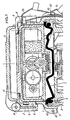
- Figure 1 une coupe dans un compteur totalisateur suivant l'invention,
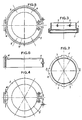
- Figures 2 et 3 respectivement une vue en plan par dessus et une coupe par 3-3 de figure 2 de la tête du compteur à une autre échelle, et
- Figures 4 à 6 respectivement une vue en plan par dessus, une vue en plan par dessous et une vue en élévation de la coiffe plastique, également à une autre échelle.
- FIG. 1 is a section through a totalizing counter according to the invention,
- Figures 2 and 3 respectively a plan view from above and a section through 3-3 of Figure 2 of the meter head on another scale, and
- Figures 4 to 6 respectively a plan view from above, a plan view from below and an elevation view of the plastic cover, also on another scale.
Comme on le voit aux dessins en figure 1 la tête 1 du compteur est séparée du corps 2 et montée sur celui-ci par l'intermédiaire d'un filetage 3.As can be seen in the drawings in FIG. 1, the
La tête 1 étant vissée sur le corps 2 maintient en place le joint de tête 4 et la plaque d'étanchéité 5.The
La partie supérieure 1′ de la tête 1 est ouverte et cylindrique pour recevoir librement un totalisateur tel que 6.The
Cette partie supérieure 1′ présente sur sa périphérie un certain nombre de trous ou mortaises 7, dans lesquels sont destinées à venir se clipser des clavettes correspondantes 8 prévues sur la paroi interne d'une coiffe plastique 9. Cette coiffe plastique 9 sert à maintenir le totalisateur 6 dans son logement dans la tête 1 au-dessus de la plaque d'étanchéité 5. Elle comporte une découpe 9′ pour permettre la lecture des données du totalisateur.This
Cette coiffe 9 comporte des moyens 10 pour le montage et le pivotement d'un couvercle 11.This
La tête 1 du compteur présente sur la périphérie de sa partie inférieure des joues 12 comportant chacune un oeillet ou trou 12′ pour permettre la liaison par fil de plombage 13 à la coiffe de plastique 9 d'une part et au corps 2 du compteur d'autre part.The
On comprend aisément de la description qui précède d'un compteur réalisé suivant l'invention qu'il suffit, après avoir rompu le fil de plombage 13 d'un compteur en service, d'enlever la coiffe de plastique 9 clipsée sur la tête 1 pour enlever le totalisateur courant 6 et le remplacer par un totalisateur avec lecture à distance sans ouvrir le compteur, donc éventuellement dans la cave de l'abonné, la plaque d'étanchéité 5 restant maintenue entre la tête 1 du compteur et le corps 2 de celui-ci.It is easily understood from the foregoing description of a counter produced according to the invention that it is sufficient, after having broken the sealing
Claims (2)
Applications Claiming Priority (2)
| Application Number | Priority Date | Filing Date | Title |
|---|---|---|---|
| BE8701323A BE1001210A3 (en) | 1987-11-20 | 1987-11-20 | Total Counters IMPROVEMENTS TO WATER. |
| BE8701323 | 1987-11-20 |
Publications (2)
| Publication Number | Publication Date |
|---|---|
| EP0317543A1 EP0317543A1 (en) | 1989-05-24 |
| EP0317543B1 true EP0317543B1 (en) | 1992-04-01 |
Family
ID=3882982
Family Applications (1)
| Application Number | Title | Priority Date | Filing Date |
|---|---|---|---|
| EP19880870171 Expired - Lifetime EP0317543B1 (en) | 1987-11-20 | 1988-11-14 | Totalizing water meters |
Country Status (2)
| Country | Link |
|---|---|
| EP (1) | EP0317543B1 (en) |
| BE (1) | BE1001210A3 (en) |
Families Citing this family (1)
| Publication number | Priority date | Publication date | Assignee | Title |
|---|---|---|---|---|
| FR2746181B1 (en) * | 1996-03-15 | 1998-05-22 | FLUID METER COMPRISING A TOTALIZER HELD BY AN ELASTIC MEMBER |
Family Cites Families (6)
| Publication number | Priority date | Publication date | Assignee | Title |
|---|---|---|---|---|
| FR813424A (en) * | 1935-08-22 | 1937-06-01 | Wassermesser Patent Ges M B H | Corrosion-proof water meter |
| DE2110813B2 (en) * | 1971-03-06 | 1975-02-06 | Bopp & Reuther Gmbh, 6800 Mannheim | Wet operation liquid counter with pulse transmission - determines rotary motion of counter decade using magnets |
| AU472768B2 (en) * | 1971-07-12 | 1976-06-03 | Email Limited | Sealed enclosure |
| BE811900A (en) * | 1974-03-05 | 1974-07-01 | METER TO MEASURE THE FLOW OF A FLUID CURRENT. | |
| US4391139A (en) * | 1982-02-24 | 1983-07-05 | Rockwell International Corporation | Plastic water meter main case |
| US4663970A (en) * | 1985-09-03 | 1987-05-12 | Rockwell International Corporation | Tamperproof water meter |
-
1987
- 1987-11-20 BE BE8701323A patent/BE1001210A3/en not_active IP Right Cessation
-
1988
- 1988-11-14 EP EP19880870171 patent/EP0317543B1/en not_active Expired - Lifetime
Also Published As
| Publication number | Publication date |
|---|---|
| BE1001210A3 (en) | 1989-08-22 |
| EP0317543A1 (en) | 1989-05-24 |
Similar Documents
| Publication | Publication Date | Title |
|---|---|---|
| EP0401085B1 (en) | Casing especially for housing electrical apparatus with built-in hinges | |
| EP0317543B1 (en) | Totalizing water meters | |
| EP1848066A2 (en) | Secured watertight electrical connection device | |
| EP0772256B1 (en) | Electrical apparatus with connection terminals protected by a diaphragm comprising wings | |
| FR2795560A1 (en) | Electrical wire grip connection/touch proof cover mechanism having wire holder/clamping screw mechanism /holder with side/top protection cover clamping screw covering. | |
| FR2710790A1 (en) | Sealed feedthrough (penetration) device | |
| EP1150404B1 (en) | Housing for electrical devices having a cable feedthrough | |
| FR2679356A1 (en) | Metering panel | |
| FR2708396A1 (en) | Air vent assembly and electrical connector intended for a sealed motor, and sealed motor using such an assembly. | |
| EP2259030B1 (en) | Fluid meter, in particular of water | |
| FR2556124A1 (en) | Covering element for uncovered terminals of a switch | |
| FR2908562A1 (en) | Anti-vandalism safety device for protecting e.g. outlet base, has screw that is activated from exterior to be moved such that screw head is located at interior of opening to prevent all movement of head and detachment of head from frame | |
| CH364826A (en) | Plug for the electrical connection of a device | |
| FR2839819A1 (en) | Clamp box for hollow closures, used to embed switch or power outlet in this closure in buildings, has pivoting units allowing rotation of clamp | |
| EP0670613B1 (en) | Electrical apparatus, comprising a device mounted in a waterproof housing, having a cover and a lid | |
| WO1981000157A1 (en) | Watch with molded dome adapted to the works | |
| JP2926588B1 (en) | Waterproof housing structure | |
| CH427659A (en) | Waterproof watch box | |
| FR2541831A1 (en) | Electrical connection box for a compressor motor | |
| FR2683047A3 (en) | DUAL TARIFF METER WITH TARIFF CHANGE APPARATUS. | |
| EP0487363A1 (en) | Work table with a cable feedthrough cover | |
| FR2685984A1 (en) | Consumer electrical panel | |
| EP1585200A1 (en) | Sealed electrical connecting device | |
| FR2692099A1 (en) | Variable height enclosure for electrical equipment - has adjustable open flange with one or more rings of low resistance to eliminate terminal section, attached to case | |
| FR2580345A2 (en) | Fastening device for an embeddable appliance |
Legal Events
| Date | Code | Title | Description |
|---|---|---|---|
| PUAI | Public reference made under article 153(3) epc to a published international application that has entered the european phase |
Free format text: ORIGINAL CODE: 0009012 |
|
| AK | Designated contracting states |
Kind code of ref document: A1 Designated state(s): FR GB NL |
|
| 17P | Request for examination filed |
Effective date: 19891106 |
|
| 17Q | First examination report despatched |
Effective date: 19910313 |
|
| GRAA | (expected) grant |
Free format text: ORIGINAL CODE: 0009210 |
|
| AK | Designated contracting states |
Kind code of ref document: B1 Designated state(s): FR GB NL |
|
| PG25 | Lapsed in a contracting state [announced via postgrant information from national office to epo] |
Ref country code: GB Effective date: 19920401 Ref country code: NL Effective date: 19920401 |
|
| NLV1 | Nl: lapsed or annulled due to failure to fulfill the requirements of art. 29p and 29m of the patents act | ||
| GBV | Gb: ep patent (uk) treated as always having been void in accordance with gb section 77(7)/1977 [no translation filed] | ||
| PLBE | No opposition filed within time limit |
Free format text: ORIGINAL CODE: 0009261 |
|
| STAA | Information on the status of an ep patent application or granted ep patent |
Free format text: STATUS: NO OPPOSITION FILED WITHIN TIME LIMIT |
|
| 26N | No opposition filed | ||
| PGFP | Annual fee paid to national office [announced via postgrant information from national office to epo] |
Ref country code: FR Payment date: 20021128 Year of fee payment: 15 |
|
| PG25 | Lapsed in a contracting state [announced via postgrant information from national office to epo] |
Ref country code: FR Free format text: LAPSE BECAUSE OF NON-PAYMENT OF DUE FEES Effective date: 20040730 |
|
| REG | Reference to a national code |
Ref country code: FR Ref legal event code: ST |