EP0316098B1 - Stapelvorrichtung - Google Patents
Stapelvorrichtung Download PDFInfo
- Publication number
- EP0316098B1 EP0316098B1 EP88310216A EP88310216A EP0316098B1 EP 0316098 B1 EP0316098 B1 EP 0316098B1 EP 88310216 A EP88310216 A EP 88310216A EP 88310216 A EP88310216 A EP 88310216A EP 0316098 B1 EP0316098 B1 EP 0316098B1
- Authority
- EP
- European Patent Office
- Prior art keywords
- products
- support means
- main support
- batch
- stack
- Prior art date
- Legal status (The legal status is an assumption and is not a legal conclusion. Google has not performed a legal analysis and makes no representation as to the accuracy of the status listed.)
- Expired - Lifetime
Links
- 230000007246 mechanism Effects 0.000 claims description 14
- 238000003780 insertion Methods 0.000 claims 1
- 230000037431 insertion Effects 0.000 claims 1
- 239000000047 product Substances 0.000 description 59
- 230000003287 optical effect Effects 0.000 description 2
- TVEXGJYMHHTVKP-UHFFFAOYSA-N 6-oxabicyclo[3.2.1]oct-3-en-7-one Chemical compound C1C2C(=O)OC1C=CC2 TVEXGJYMHHTVKP-UHFFFAOYSA-N 0.000 description 1
- 238000009825 accumulation Methods 0.000 description 1
- 230000000712 assembly Effects 0.000 description 1
- 238000000429 assembly Methods 0.000 description 1
- 239000006227 byproduct Substances 0.000 description 1
- 239000011111 cardboard Substances 0.000 description 1
- 238000000034 method Methods 0.000 description 1
- 239000000123 paper Substances 0.000 description 1
- 239000011087 paperboard Substances 0.000 description 1
- 230000000284 resting effect Effects 0.000 description 1
- 230000000717 retained effect Effects 0.000 description 1
Images
Classifications
-
- B—PERFORMING OPERATIONS; TRANSPORTING
- B65—CONVEYING; PACKING; STORING; HANDLING THIN OR FILAMENTARY MATERIAL
- B65G—TRANSPORT OR STORAGE DEVICES, e.g. CONVEYORS FOR LOADING OR TIPPING, SHOP CONVEYOR SYSTEMS OR PNEUMATIC TUBE CONVEYORS
- B65G57/00—Stacking of articles
- B65G57/02—Stacking of articles by adding to the top of the stack
- B65G57/03—Stacking of articles by adding to the top of the stack from above
-
- B—PERFORMING OPERATIONS; TRANSPORTING
- B65—CONVEYING; PACKING; STORING; HANDLING THIN OR FILAMENTARY MATERIAL
- B65H—HANDLING THIN OR FILAMENTARY MATERIAL, e.g. SHEETS, WEBS, CABLES
- B65H31/00—Pile receivers
- B65H31/30—Arrangements for removing completed piles
- B65H31/3054—Arrangements for removing completed piles by moving the surface supporting the lowermost article of the pile, e.g. by using belts or rollers
-
- B—PERFORMING OPERATIONS; TRANSPORTING
- B65—CONVEYING; PACKING; STORING; HANDLING THIN OR FILAMENTARY MATERIAL
- B65H—HANDLING THIN OR FILAMENTARY MATERIAL, e.g. SHEETS, WEBS, CABLES
- B65H31/00—Pile receivers
- B65H31/30—Arrangements for removing completed piles
- B65H31/3081—Arrangements for removing completed piles by acting on edge of the pile for moving it along a surface, e.g. by pushing
-
- B—PERFORMING OPERATIONS; TRANSPORTING
- B65—CONVEYING; PACKING; STORING; HANDLING THIN OR FILAMENTARY MATERIAL
- B65H—HANDLING THIN OR FILAMENTARY MATERIAL, e.g. SHEETS, WEBS, CABLES
- B65H2301/00—Handling processes for sheets or webs
- B65H2301/40—Type of handling process
- B65H2301/42—Piling, depiling, handling piles
- B65H2301/422—Handling piles, sets or stacks of articles
- B65H2301/4226—Delivering, advancing piles
- B65H2301/42266—Delivering, advancing piles by acting on edge of the pile for moving it along a surface, e.g. pushing
-
- B—PERFORMING OPERATIONS; TRANSPORTING
- B65—CONVEYING; PACKING; STORING; HANDLING THIN OR FILAMENTARY MATERIAL
- B65H—HANDLING THIN OR FILAMENTARY MATERIAL, e.g. SHEETS, WEBS, CABLES
- B65H2701/00—Handled material; Storage means
- B65H2701/10—Handled articles or webs
- B65H2701/17—Nature of material
- B65H2701/176—Cardboard
- B65H2701/1766—Cut-out, multi-layer, e.g. folded blanks or boxes
-
- Y—GENERAL TAGGING OF NEW TECHNOLOGICAL DEVELOPMENTS; GENERAL TAGGING OF CROSS-SECTIONAL TECHNOLOGIES SPANNING OVER SEVERAL SECTIONS OF THE IPC; TECHNICAL SUBJECTS COVERED BY FORMER USPC CROSS-REFERENCE ART COLLECTIONS [XRACs] AND DIGESTS
- Y10—TECHNICAL SUBJECTS COVERED BY FORMER USPC
- Y10S—TECHNICAL SUBJECTS COVERED BY FORMER USPC CROSS-REFERENCE ART COLLECTIONS [XRACs] AND DIGESTS
- Y10S414/00—Material or article handling
- Y10S414/10—Associated with forming or dispersing groups of intersupporting articles, e.g. stacking patterns
- Y10S414/106—Associated with forming or dispersing groups of intersupporting articles, e.g. stacking patterns including means for supplying pallet or separator to group
Definitions
- THIS INVENTION relates to stacking equipment particularly, though not exclusively, for stacking products formed from corrugated board or other paper or board products (especially boxes or cartons in lay-flat form) on pallets.
- Corrugated board is converted into cartons or boxes in lay-flat form with automatic machinery and stacks of such lay-flat products are discharged from an outlet conveyor.
- the discharged stacks can then be accumulated as larger stacks on pallets for convenience of transport and storage.
- the discharged stacks are commonly transferred to the pallets by hand but this can be arduous and inefficient.
- European Patent Specification No. 0126694 describes apparatus for forming a stack of articles and including a receiving conveyor on which a batch of articles is collected, a main support device for supporting such batches at a stacking location, and transfer means for transferring the batches from the receiving conveyor to the main support device and for introducing each successive batch beneath a preceding transferred batch whereby a stack of the batches is formed on the main support means.
- the apparatus described in that document relies upon the articles of each batch being positioned exactly beneath the bounds of the stack as it is formed, no means being provided for squaring the articles in each batch or each batch in the stack.
- An object of the present invention is to provide stacking equipment whereby transfer of products to a stacking location can be effected automatically in a convenient and efficient manner with each stack properly centralised over its pallet.
- stacking equipment comprising receiving means for receiving and conveying products to be stacked, collecting means for collecting said conveyed products together in predetermined disposition in successive batches, a main support means for supporting such batches at a stacking location, and transfer means for transferring said batches from said collecting means to said main support means and for introducing each successive batch beneath a preceding transferred batch whereby a stack of said batches is formed on said main support means, characterised in that said collecting means includes at least two deflectors simultaneously movable towards and away from each other transversely of the conveying direction of the products to centralise the transverse disposition of an assembled batch of products before transfer to said main support means; and in that vertically disposed structures are provided above the main support means and simultaneously movable towards and away from each other in a direction parallel to the conveying direction of the products to centralise the longitudinal disposition of the stacked batches over the main support means so that transverse centering occurs over the collecting means, and longitudinal centering occurs over the main support means.
- the receiving means may comprise a conveyor, such as a roller conveyor, which may run continuously. Where the stacking equipment is used with product-producing automatic machinery, an input end of the receiving means may be arranged to receive products automatically from an output of the machinery.
- the transfer means may comprise an auxiliary support means above the main support means in conjunction with mechanisms which act automatically to transfer each batch from the collecting means to the main support means and from there to the auxiliary support means beneath any batch already on the latter support means, the final assembly of stacked batches then being deposited from the auxiliary support means onto the main support means.
- the main support means and the auxiliary support means may be vertically movable one relative to the other for transfer of batches therebetween.
- the auxiliary support means may comprise retractable fingers which can be readily inserted beneath and retracted from batches on the main support means.
- the main support means may comprise a roller bed and the rollers may be arranged such that the above mentioned fingers fit therebetween.
- the final assembly of stacked batches may be deposited on a pallet on the main support means and an automatic feed device may be provided for feeding the pallet onto the main support means prior to deposit of the stacked batches thereon.
- the invention may find particular application in the stacking of corrugated board products.
- the invention is not intended to be restricted to this context and the stacking equipment may be used for any suitable purpose.
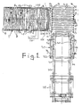
- the equipment shown in the drawings is for use in the automatic assembly of stacks of flat corrugated board products on pallets.
- the equipment includes a receiving conveyor 1 comprising a horizontal bed of rollers 2 which can be continuously driven by an electric motor drive mechanism.
- the bed stands on adjustable legs 3 and has an inlet end 4 which can be arranged to receive products directly from an outlet end of product-producing machinery.
- the products delivered onto the conveyor 1 may be in the form of several superimposed corrugated board boxes or cartons in lay-flat form and the boxes or cartons may be loosely superimposed or may be tied together.
- a detector 100 is provided at the inlet end 4 of the conveyor 1 for detecting delivery of products onto the conveyor.
- the detector may be of the optical kind i.e. a light sensor receiving light from a source, such light being interrupted by the intrusion of delivery products.
- the conveyor 1 is bounded at its sides by upstanding frames 5 and, near to the inlet end 4, there is a turntable 6 set into the roller bed.
- the turntable 6 is normally retracted beneath the roller bed but can be moved upwardly and can be rotated about a vertical axis with an automatic drive mechanism 101. In this way the products can be rotated through a predetermined angle as they pass along the conveyor 1.
- each set can be moved, between the conveyor rollers 2, across the conveyor 1 towards the other set, with an automatic drive mechanism 102. In this way the products can be shifted to either side of the conveyor 1.
- a detector 103 Adjacent each set of push rods 7 there is a detector 103 (e.g. an optical detector) for detecting the presence of products thereat.
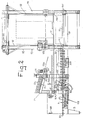
- a stop plate 10 which can be moved, by an automatic drive mechanism 105, between a retracted position in which it is below the roller bed, and an extended position at which it is above the roller bed and acts as an abutment for products on the conveyor 1.
- a push plate arrangement 11 mounted on pivotal arms 12 so that it can be moved, as illustrated by arrow 106, by an automatic drive mechanism, between an operational position in which it extends across the conveyor 1 slightly above the roller bed, and a retracted position at which it is above and well clear of the roller bed. In the operational position the push plate 11 can be moved along the conveyor 1 towards the stop plate 10.
- the outlet end 9 of the conveyor 1 is arranged to discharge to one side of a vertical frame structure 13.
- the frame structure 13 has upright columns 14 and mounted therebetween near the bottom is a platform 15 having a bed of support rollers 16 which can be rotated with a drive motor 107.
- the axes of the rollers 16 are horizontal and perpendicular to the axes of the conveying rollers 2.
- the platform 15 can be moved, with a drive mechanism 108, between a lower position (as illustrated) level with the conveyor 1 and a higher position.
- the various drive mechanisms and detectors so far described, and various limit switches (not yet described) associated with parts of the equipment, are all connected to a computer control unit 112 with which the desired operation of the equipment can be selected and automatically controlled.
- the control unit preferably has a VDU which produces a graphics display to assist the operator in selecting the desired orientation and mode of assembly of products on the conveyor.
- tie sheets are sheets of paper or cardboard of which one is placed on the top of each successive batch of products prior to delivery onto the rollers 16.
- tie sheets disposed between successive batches of products will assist in maintaining stability of the finished stack. This is particularly useful when the products consist of loosely tied bundles of lay-flat articles where each bundle is not necessarily of uniform height throughout its length and width.
- the dispenser 20 comprises a supporting platform 21 on which a bundle of tie sheets 22 may be stored, and a vertically adjustable gate 23 forming a front wall against which the tie sheets lie.
- a friction roller 24 mounted beneath the leading edge of the lowermost sheet 22, and driven by motor 25, may serve to dispense a tie sheet as indicated at 22a onto the top of an accumulated batch of products on the conveyor 1.
- a pallet dispenser generally indicated at 30 is preferably located adjacent one end of the bed of rollers 16 for the purpose of transferring a pallet onto the rollers 16 to be placed beneath a finished stack prior to the introduction of the next successive batch of products.
- the dispenser 30 comprises a first station 31 on which pallets may be stored in a stack, a second station 32 in which a stack of pallets may be supported, and a transfer platform 33 adapted to run along rails 34 to transfer stacks of pallets successively between stations 31 and 32.
- Station 32 is equipped with retractable vertical side supports 35 which, by means of pneumatic cylinders 36, are movable towards one another to grip a stack of pallets.
- the vertical supports 35 extend downwardly to a position above the level of the height of a single pallet so that when a stack of pallets is supported by supports 35 the lowermost unsupported pallet may be advanced by platform 33 into an operative position on the bed of rollers 16.
- Platform 33 By successively manipulating vertical supports 35 and platform 33, pallets may be supplied beneath successive finished stacks of products.
- Supports 35 are also movable vertically to lower a stack of pallets on each occasion when the lowermost pallet is delivered onto rollers 16.
- Typical operation of the equipment is as follows.
- the operator sets the control unit in accordance with a desired orientation and assembly of products in the final stack. That is, products (or small stacks of products) may be delivered to the receiving conveyor 1 with a fixed common orientation and one behind another, but the stacking requirement may be that the products should be arranged e.g. side-by-side facing in opposite directions, especially where the products are of non-uniform (tapered) thickness. Accordingly, it may be necessary to set the control unit to cause the equipment to turn and move sideways the products (in the manner described hereinafter).
- the rollers 2 of the conveyor 1 are set in continuous motion and products are fed (manually or automatically) onto the inlet end 4 of the conveyor 1 along the centre line of the conveyor.
- the turntable 6 is activated to move up and engage a product when its centre is aligned with the turntable centre.
- the product is rotated through a desired angle and then the turntable 6 is retracted to deposit the product back on the conveyor 1.
- next product is rotated by the turntable 6 in the opposite direction and pushed to the opposite side whereby the two products are then arranged side-by-side facing in opposite directions against the stop plate 10.
- one or more products may be centralised by simultaneous operation of both sets of push rods 7.
- the deflectors 8 then move towards each other in accordance with a timed sequence to centralise the transverse disposition of the assembled batch of products on the conveyor 1. This sequence may be repeated to form an accumulation of products as a batch on the conveyor 1.
- a tie sheet is placed on its top surface as described above and then the stop plate 10 is retracted, the push plate 11 is lowered into the operational position behind the batch and is advanced to push the batch of products off the conveyor 1 onto the platform 15, such action terminating when a limit switch is engaged by the push plate 11.
- the push plate 11 is pivotted upwardly clear of the conveyor 1 and returned to its starting position, and the stop plate 10 is raised to lie above the roller bed of the conveyor 1.
- the platform 15 With the fork 17 in their extended positions resting on supports 110, the platform 15 is moved upwardly until the forks 17 are engaged by the supported batch. A limit switch is thereby actuated, the forks 17 are retracted, the platform 15 is moved slightly higher to its uppermost position, and the forks 17 are again extended to pass between the rollers 16 and beneath the supported products to rest on supports 110.
- the platform 15 descends to its lowermost position leaving the products supported on the forks 17.
- each successive batch is transferred onto the forks 17 beneath the preceding assembly (or stack of assemblies). That is, when the supported products on the platform 15 are moved up into engagement with the forks 17, the forks 17 retract so as to drop onto the supported products, all those products which were already on the forks and the resulting increased stack is then transferred back to the forks 17.
- the conveyor 1 When a stack of desired height has been assembled on the forks 17, the conveyor 1 is stopped, a pallet is positioned on the platform 15 (from the pallet dispenser 30), the platform 15 is raised, the forks 17 are retracted to deposit the stack onto the pallet, the platform 15 descends to its lowermost position, and the rollers 16 of the platform 15 are driven to discharge the palletised stack to a delivery conveyor or the like positioned opposite pallet dispenser 30.
- palletised stacks can be formed in a particularly convenient and efficient manner. Transverse centering of the batches is ensured by the action of deflectors 8 and longitudinal centering is ensured by the action of vertical fingers 18.
Landscapes
- Mechanical Engineering (AREA)
- Engineering & Computer Science (AREA)
- Stacking Of Articles And Auxiliary Devices (AREA)
- Fuel Cell (AREA)
- Pile Receivers (AREA)
- Spinning Or Twisting Of Yarns (AREA)
- Massaging Devices (AREA)
- Medicines Containing Plant Substances (AREA)
- Measuring Pulse, Heart Rate, Blood Pressure Or Blood Flow (AREA)
- Filters For Electric Vacuum Cleaners (AREA)
- Agricultural Chemicals And Associated Chemicals (AREA)
- Magnetic Resonance Imaging Apparatus (AREA)
- Debugging And Monitoring (AREA)
- Glass Compositions (AREA)
- Telephone Function (AREA)
- Packages (AREA)
- Organic Low-Molecular-Weight Compounds And Preparation Thereof (AREA)
- Diaphragms For Electromechanical Transducers (AREA)
Claims (12)
- Stapelausrüstung mit einer Aufnahmeeinrichtung (1) zum Empfangen und Fördern von zu stapelnden Produkten, einer Sammeleinrichtung (2, 6, 7, 10) zum Zusammensammeln der geförderten Produkte in vorbestimmter Anordnung in aufeinanderfolgenden Partien, einer Haupttrageinrichtung (16) zum Tragen dieser Partien an einem Stapelort und einer Übergabeeinrichtung (11, 12) zum Übergeben der Partien von der Sammeleinrichtung (2, 6, 7, 10) an die Haupttrageinrichtung (16) und zum Einführen jeder folgenden Partie unter eine vorhergehende übergebene Partie, wodurch ein Stapel der Partien auf der Haupttrageinrichtung (16) gebildet wird, dadurch gekennzeichnet, daß die Sammeleinrichtung (2, 6, 7, 10) wenigstens zwei Ablenker (8) aufweist, die quer zu der Förderrichtung der Produkte gleichzeitig aufeinander zu und voneinander weg bewegbar sind, um die Queranordnung einer zusammengesetzten Partie von Produkten vor der Übergabe an die Haupttrageinrichtung (16) zu zentralisieren; und daß vertikal angeordnete Gebilde (18) oberhalb der Haupttrageinrichtung (16) vorgesehen und in einer zu der Förderrichtung der Produkte parallelen Richtung gleichzeitig aufeinander zu- und von einander wegbewegbar sind, um die Längsanordnung der gestapelten Partien über der Haupttrageinrichtung (16) zu zentralisieren, so daß eine Querzentrierung über der Sammeleinrichtung erfolgt und eine Längszentrierung über der Haupttrageinrichtung (16) erfolgt.
- Stapelausrüstung nach Anspruch 1, wobei die Aufnahmeeinrichtung (1) einen angetriebenen Förderer (2) aufweist, der dafür ausgebildet und angeordnet ist, aufeinanderfolgende Produkte zu empfangen, die auf ihn zu einer Partie zusammengesetzt werden sollen und von derselben durch die Übergabeeinrichtung (11, 12) an die Haupttrageinrichtung (16) abgegeben werden sollen.
- Stapelausrüstung nach Anspruch 1 oder Anspruch 2, wobei die Sammeleinrichtung (2, 6, 7, 10) eine bewegliche Anschlagplatte (10) und einen Drehtisch (6) zum Einstellen der Winkelanordnung der Produkte aufweist.
- Stapelausrüstung nach irgendeinem vorhergehenden Anspruch, mit einer Hilfstrageinrichtung (17) oberhalb der Haupttrageinrichtung (16) und Mechanismen, welche automatisch arbeiten, um jede Partie von Produkten von der Sammeleinrichtung (2, 6, 7, 10) an die Haupttrageinrichtung (16) und von dieser aus an die Hilfstrageinrichtung (17) unterhalb jeder auf letzterer bereits angeordneten Partie zu übergeben.
- Stapelausrüstung nach Anspruch 4, wobei die Haupttrageinrichtung (16) und die Hilfstrageinrichtung (17) relativ zueinander vertikal bewegbar sind, um Partien von Produkten zwischen sich zu übergeben.
- Stapelausrüstung nach Anspruch 4 oder Anspruch 5, wobei die Hilfstrageinrichtung (17) mehrere parallele, zurückziehbare Finger aufweist, die zum Einführen unter eine oder mehrere Partien, die auf der Haupttrageinrichtung (16) gehalten sind, und zum Darunterhervorziehen ausgebildet sind.
- Stapelausrüstung nach Anspruch 6, wobei die Haupttrageinrichtung (16) ein Bett von parallelen Rollen aufweist und die zurückziehbaren Finger vertikal mit den Zwischenräumen zwischen den Rollen ausgerüstet sind.
- Stapelausrüstung nach irgendeinem vorhergehenden Anspruch, mit einem Palettenspender (30), der neben der Haupttrageinrichtung (16) angeordnet und dafür ausgebildet ist, ein Magazin für einen Stapel von Paletten zu bilden, und eine Einrichtung (33) aufweist zum aufeinanderfolgenden Abgeben von Paletten aus dem Magazin an die Haupttrageinrichtung (16) zum Plazieren unterhalb eines fertigen Stapels von Produkten.
- Stapelausrüstung nach Anspruch 8, wobei der Palettenspender (30) vertikale Teile (35) aufweist zum Abstützen von entgegengesetzten Seiten eines Stapels von Paletten und die Fördereinrichtung (33) zum Übergeben der untersten Palette von unterhalb eines Stapels derselben aus an die Haupttrageinrichtung (16), während der Stapel von Paletten darüber durch die vertikalen Teile gehalten ist.
- Stapelausrüstung nach irgendeinem vorhergehenden Anspruch, mit einem Verbindungsblattspender (20), der eine Einrichtung aufweist zum Tragen eines Stapels von Verbindungsblättern (22) und eine Einrichtung (25) zum Abgeben eines Blattes aus dem Stapel auf die obere Oberfläche einer zusammengesetzten Partie von Produkten vor deren Übergabe an die Haupttrageinrichtung (16), wodurch zwischen vertikal benachbarten Partien von Produkten innerhalb des Stapels jeweils ein Verbindungsblatt angeordnet wird.
- Stapelausrüstung nach Anspruch 10, wobei der Verbindungsblattspender (20) ein einstellbares Steuergatter (23) aufweist, um sicherzustellen, daß die Blätter eines nach dem anderen aus dem Spender abgegeben werden.
- Stapelausrüstung nach irgendeinem vorhergehenden Anspruch, mit mehreren Detektoren zum Bestimmen der augenblicklichen Position eines Produkts oder einer Partie desselben innerhalb der Ausrüstung und mit einer Computersteuereinheit (112), die so angeschlossen ist, daß sie Signale aus den Detektoren empfängt und gemäß einer vorbestimmten Zeitfolge verschiedene Antriebsmechanismen für die Komponenten der Ausrüstung betätigt, so daß der gewünschte Betrieb der Ausrüstung gewählt und automatisch gesteuert werden kann.
Priority Applications (1)
| Application Number | Priority Date | Filing Date | Title |
|---|---|---|---|
| AT8888310216T ATE104922T1 (de) | 1987-11-07 | 1988-10-31 | Stapelvorrichtung. |
Applications Claiming Priority (2)
| Application Number | Priority Date | Filing Date | Title |
|---|---|---|---|
| GB8726152 | 1987-11-07 | ||
| GB878726152A GB8726152D0 (en) | 1987-11-07 | 1987-11-07 | Stacking equipment |
Publications (3)
| Publication Number | Publication Date |
|---|---|
| EP0316098A2 EP0316098A2 (de) | 1989-05-17 |
| EP0316098A3 EP0316098A3 (en) | 1990-05-16 |
| EP0316098B1 true EP0316098B1 (de) | 1994-04-27 |
Family
ID=10626628
Family Applications (1)
| Application Number | Title | Priority Date | Filing Date |
|---|---|---|---|
| EP88310216A Expired - Lifetime EP0316098B1 (de) | 1987-11-07 | 1988-10-31 | Stapelvorrichtung |
Country Status (17)
| Country | Link |
|---|---|
| US (1) | US4993907A (de) |
| EP (1) | EP0316098B1 (de) |
| JP (1) | JPH01167176A (de) |
| KR (1) | KR890008003A (de) |
| AT (1) | ATE104922T1 (de) |
| AU (1) | AU602262B2 (de) |
| CA (1) | CA1309427C (de) |
| CS (1) | CS728488A3 (de) |
| DE (1) | DE3889295T2 (de) |
| DK (1) | DK617988A (de) |
| ES (1) | ES2053761T3 (de) |
| FI (1) | FI885105A (de) |
| GB (2) | GB8726152D0 (de) |
| HU (1) | HUT49311A (de) |
| NO (1) | NO884923L (de) |
| NZ (1) | NZ226805A (de) |
| PT (1) | PT88954A (de) |
Families Citing this family (16)
| Publication number | Priority date | Publication date | Assignee | Title |
|---|---|---|---|---|
| US5096371A (en) * | 1990-04-17 | 1992-03-17 | Fleetwood Systems, Inc. | Carton feeding apparatus |
| US5102282A (en) * | 1990-10-09 | 1992-04-07 | The Procter & Gamble Company | Unit load transfer device and method |
| US5139388A (en) * | 1991-01-28 | 1992-08-18 | Merrill David Martin | Load former--palletizer |
| US5339957A (en) * | 1993-03-08 | 1994-08-23 | Key Tech Corporation | High friction package retainer |
| US5715660A (en) * | 1995-12-05 | 1998-02-10 | Balentine; Paul | Automated product collection apparatus |
| US5813826A (en) * | 1997-02-21 | 1998-09-29 | Martain Family Trust | Bottom sheet dispenser for load forming machinery |
| US5788460A (en) * | 1997-04-01 | 1998-08-04 | Lithibar Matik, Inc. | Method and apparatus for patterning concrete blocks and products |
| US7581919B2 (en) * | 2005-05-23 | 2009-09-01 | Feon Societa' A Responsabilita' Limitata | Universal method for the quick layer palletization of objects and relative system with rollup planes |
| US20080019819A1 (en) * | 2006-07-19 | 2008-01-24 | Lorin Reed | Palletizer apparatus and method |
| CA2715455C (en) * | 2009-09-25 | 2015-04-28 | Johnsen Machine Company Ltd. | Palletizing system and method |
| DE102010050607A1 (de) * | 2010-11-05 | 2012-05-10 | Grenzebach Maschinenbau Gmbh | Vorrichtung und Verfahren zum schnellen Zusammenstellen von Kommissionsware für den Transport |
| KR101323244B1 (ko) * | 2013-06-28 | 2013-10-30 | (주) 신흥이엔지 | 맨홀제조장치 |
| CN103693464B (zh) * | 2013-12-26 | 2016-05-11 | 南通通机股份有限公司 | 一种全自动纸板供应系统 |
| JP6796852B2 (ja) * | 2016-07-07 | 2020-12-09 | 株式会社Isowa | 段ボールシート製函機、およびシート給送制御装置 |
| CN107244451B (zh) * | 2017-06-21 | 2019-03-01 | 中节能太阳能科技(镇江)有限公司 | 一种组件自动竖式翻转装置 |
| DE102019110704B3 (de) * | 2019-04-25 | 2020-05-14 | Stöcklin Logistik Ag | Vorrichtung und Verfahren zum Depalettieren von stapelbaren Stückgutgebinden |
Family Cites Families (24)
| Publication number | Priority date | Publication date | Assignee | Title |
|---|---|---|---|---|
| US3235100A (en) * | 1961-11-09 | 1966-02-15 | Mathews Conveyor Company | Automatic case stacker |
| US3343694A (en) * | 1963-10-15 | 1967-09-26 | Kaukas Ab Oy | Method for composing a timber packet |
| US3220570A (en) * | 1964-02-04 | 1965-11-30 | Package Machinery Co | Assembly and wrapping of groups of articles |
| DE1255024B (de) * | 1965-10-26 | 1967-11-23 | Benz & Hilgers G M B H | Vorrichtung zum Einschachteln von mehreren neben- und uebereinander angeordneten prismatischen Packungen in einen Sammelbehaelter |
| US3523601A (en) * | 1967-03-02 | 1970-08-11 | Alvey Inc | Carton palletizing apparatus |
| US3934713A (en) * | 1971-08-02 | 1976-01-27 | Ball Corporation | Method and apparatus for palletizing articles |
| DE2211793C3 (de) * | 1972-03-11 | 1978-08-17 | Holstein Und Kappert Ag, 4600 Dortmund | Vorrichtung zum Bereitstellen von Gefäßen |
| BE788123A (fr) * | 1972-08-29 | 1972-12-18 | Leenaards Antoine | Palettiseur. |
| US3788497A (en) * | 1972-09-27 | 1974-01-29 | K Carlson | Flow-thru palletizer and depalletizer |
| CH561631A5 (de) * | 1973-02-12 | 1975-05-15 | Sig Schweiz Industrieges | |
| FR2319554A2 (fr) * | 1975-07-31 | 1977-02-25 | Thibault Jacques | Machine pour charger des colis sur u |
| US4271755A (en) * | 1978-10-25 | 1981-06-09 | Master Conveyor Corporation | Bag handling apparatus |
| NL175714C (nl) * | 1979-01-30 | 1984-12-17 | Joh S Aberson B V Maschf | Inrichting voor het maken van een uit meerdere rijen bestaande stapel van stenen. |
| FR2450220A1 (fr) * | 1979-02-28 | 1980-09-26 | Thibault Jacques | Appareil d'empilage et depilage, par le dessous, de couches de colis |
| US4341299A (en) * | 1980-05-08 | 1982-07-27 | Mccorquodale Machine Systems Limited | Apparatus for performing operations on a stack of sheets |
| IT8135819V0 (it) * | 1981-05-20 | 1981-05-20 | Giampiero Giusti | Impilatore automatico per pile difogli |
| FR2542294B1 (fr) * | 1983-03-11 | 1985-08-02 | Bobst | Dispositif d'empilage automatique notamment d'elements en plaque superposes a plat |
| US4540325A (en) * | 1983-04-18 | 1985-09-10 | Heisler Raymond A | Upstacker apparatus with biased gripping means |
| FR2546144A1 (fr) * | 1983-05-20 | 1984-11-23 | Fortea Michel | Procede et dispositif pour palettiser des charges unitaires |
| JPS6127869A (ja) * | 1984-07-13 | 1986-02-07 | Nichiro Kogyo Kk | 折帖印刷物の小束段積み装置 |
| US4778323A (en) * | 1985-09-13 | 1988-10-18 | Besser Company | Bag palletizing system and method |
| FR2587311A1 (fr) * | 1985-09-18 | 1987-03-20 | Schauman | Procede et installation de manutention automatique et stockage temporaire de paquets empiles de produits semi-finis en feuilles. |
| DE3627498A1 (de) * | 1986-08-13 | 1988-02-25 | Thomas C Barnickel | Vorrichtung zum ausrichten und anordnen von packstuecken |
| FR2619094B1 (fr) * | 1987-08-05 | 1989-12-15 | Bobst Sa | Dispositif d'empilage d'objets plats disposes en paquets |
-
1987
- 1987-11-07 GB GB878726152A patent/GB8726152D0/en active Pending
-
1988
- 1988-10-31 ES ES88310216T patent/ES2053761T3/es not_active Expired - Lifetime
- 1988-10-31 GB GB8825459A patent/GB2212144B/en not_active Expired - Lifetime
- 1988-10-31 DE DE3889295T patent/DE3889295T2/de not_active Expired - Fee Related
- 1988-10-31 AT AT8888310216T patent/ATE104922T1/de not_active IP Right Cessation
- 1988-10-31 EP EP88310216A patent/EP0316098B1/de not_active Expired - Lifetime
- 1988-10-31 US US07/264,522 patent/US4993907A/en not_active Expired - Fee Related
- 1988-11-01 NZ NZ226805A patent/NZ226805A/en unknown
- 1988-11-03 CA CA000582204A patent/CA1309427C/en not_active Expired - Lifetime
- 1988-11-04 HU HU885719A patent/HUT49311A/hu unknown
- 1988-11-04 NO NO88884923A patent/NO884923L/no unknown
- 1988-11-04 AU AU24695/88A patent/AU602262B2/en not_active Ceased
- 1988-11-04 FI FI885105A patent/FI885105A/fi not_active IP Right Cessation
- 1988-11-04 CS CS887284A patent/CS728488A3/cs unknown
- 1988-11-04 DK DK617988A patent/DK617988A/da not_active Application Discontinuation
- 1988-11-05 JP JP63280232A patent/JPH01167176A/ja active Pending
- 1988-11-07 PT PT88954A patent/PT88954A/pt not_active Application Discontinuation
- 1988-11-07 KR KR1019880014613A patent/KR890008003A/ko not_active Application Discontinuation
Also Published As
| Publication number | Publication date |
|---|---|
| NO884923D0 (no) | 1988-11-04 |
| NO884923L (no) | 1989-05-08 |
| PT88954A (pt) | 1989-09-14 |
| EP0316098A2 (de) | 1989-05-17 |
| GB8726152D0 (en) | 1987-12-09 |
| JPH01167176A (ja) | 1989-06-30 |
| ATE104922T1 (de) | 1994-05-15 |
| KR890008003A (ko) | 1989-07-08 |
| CA1309427C (en) | 1992-10-27 |
| ES2053761T3 (es) | 1994-08-01 |
| DE3889295T2 (de) | 1994-10-27 |
| DE3889295D1 (de) | 1994-06-01 |
| FI885105A (fi) | 1989-05-08 |
| GB8825459D0 (en) | 1988-11-30 |
| AU602262B2 (en) | 1990-10-04 |
| NZ226805A (en) | 1991-04-26 |
| EP0316098A3 (en) | 1990-05-16 |
| GB2212144B (en) | 1991-10-02 |
| FI885105A0 (fi) | 1988-11-04 |
| DK617988A (da) | 1989-05-08 |
| US4993907A (en) | 1991-02-19 |
| HUT49311A (en) | 1989-09-28 |
| DK617988D0 (da) | 1988-11-04 |
| GB2212144A (en) | 1989-07-19 |
| CS728488A3 (en) | 1992-11-18 |
| AU2469588A (en) | 1989-05-11 |
Similar Documents
| Publication | Publication Date | Title |
|---|---|---|
| EP0316098B1 (de) | Stapelvorrichtung | |
| US5961275A (en) | Palletizer and palletizing methods | |
| US4764074A (en) | Pallet loading apparatus | |
| US7802959B2 (en) | Compact palletizer | |
| US3567046A (en) | Device for the manipulation of laminar objects particularly for laying-up the same in a pile | |
| NL8801059A (nl) | Inrichting voor het stapelen van bundels platgevouwen dozen van golfkarton. | |
| EP2432717B1 (de) | Vorrichtung und verfahren zur palettierung von artikeln. | |
| US4049260A (en) | Apparatus for feeding sheets | |
| JPH0471810B2 (de) | ||
| US11565894B2 (en) | Rotary discharge of containers from a depalletizer | |
| US3964239A (en) | Packaging machine | |
| US3980183A (en) | Delivery and collecting arrangement for rotary machines for printing books or magazines | |
| US20100031612A1 (en) | Apparatus for and method of packaging stackable 0bjects, in particular printed products | |
| US5707204A (en) | Stacking apparatus | |
| JPS605503B2 (ja) | 積重ね板紙の積上げ装置 | |
| JPH0696410B2 (ja) | 自動パレタイザ装置 | |
| JPH06227663A (ja) | 物品積込装置 | |
| JPH0776051B2 (ja) | 搬送方向転換用ベルトコンベヤ装置 | |
| CN111003440B (zh) | 输送设备 | |
| JPH0610054B2 (ja) | パレタイザー | |
| JP3401709B2 (ja) | 計数スタック装置 | |
| WO2003042040A1 (en) | Method and device for loading cartons in a container | |
| JPH0120243Y2 (de) | ||
| JPH04239404A (ja) | 包装装置 | |
| JPH0524681Y2 (de) |
Legal Events
| Date | Code | Title | Description |
|---|---|---|---|
| PUAI | Public reference made under article 153(3) epc to a published international application that has entered the european phase |
Free format text: ORIGINAL CODE: 0009012 |
|
| AK | Designated contracting states |
Kind code of ref document: A2 Designated state(s): AT BE CH DE ES FR GB GR IT LI LU NL SE |
|
| PUAL | Search report despatched |
Free format text: ORIGINAL CODE: 0009013 |
|
| AK | Designated contracting states |
Kind code of ref document: A3 Designated state(s): AT BE CH DE ES FR GB GR IT LI LU NL SE |
|
| 17P | Request for examination filed |
Effective date: 19901025 |
|
| 17Q | First examination report despatched |
Effective date: 19920407 |
|
| RBV | Designated contracting states (corrected) |
Designated state(s): AT BE CH DE ES FR GR IT LI LU NL SE |
|
| GRAA | (expected) grant |
Free format text: ORIGINAL CODE: 0009210 |
|
| RAP1 | Party data changed (applicant data changed or rights of an application transferred) |
Owner name: SCM CONTAINER MACHINERY LIMITED |
|
| AK | Designated contracting states |
Kind code of ref document: B1 Designated state(s): AT BE CH DE ES FR GR IT LI LU NL SE |
|
| PG25 | Lapsed in a contracting state [announced via postgrant information from national office to epo] |
Ref country code: SE Free format text: THE PATENT HAS BEEN ANNULLED BY A DECISION OF A NATIONAL AUTHORITY Effective date: 19940427 Ref country code: NL Effective date: 19940427 Ref country code: LI Effective date: 19940427 Ref country code: GR Free format text: LAPSE BECAUSE OF FAILURE TO SUBMIT A TRANSLATION OF THE DESCRIPTION OR TO PAY THE FEE WITHIN THE PRESCRIBED TIME-LIMIT Effective date: 19940427 Ref country code: CH Effective date: 19940427 Ref country code: BE Effective date: 19940427 Ref country code: AT Effective date: 19940427 |
|
| REF | Corresponds to: |
Ref document number: 104922 Country of ref document: AT Date of ref document: 19940515 Kind code of ref document: T |
|
| REF | Corresponds to: |
Ref document number: 3889295 Country of ref document: DE Date of ref document: 19940601 |
|
| ITF | It: translation for a ep patent filed | ||
| REG | Reference to a national code |
Ref country code: CH Ref legal event code: PL |
|
| REG | Reference to a national code |
Ref country code: ES Ref legal event code: FG2A Ref document number: 2053761 Country of ref document: ES Kind code of ref document: T3 |
|
| ET | Fr: translation filed | ||
| NLV1 | Nl: lapsed or annulled due to failure to fulfill the requirements of art. 29p and 29m of the patents act | ||
| PG25 | Lapsed in a contracting state [announced via postgrant information from national office to epo] |
Ref country code: LU Free format text: LAPSE BECAUSE OF NON-PAYMENT OF DUE FEES Effective date: 19941031 |
|
| PLBE | No opposition filed within time limit |
Free format text: ORIGINAL CODE: 0009261 |
|
| STAA | Information on the status of an ep patent application or granted ep patent |
Free format text: STATUS: NO OPPOSITION FILED WITHIN TIME LIMIT |
|
| 26N | No opposition filed | ||
| PGFP | Annual fee paid to national office [announced via postgrant information from national office to epo] |
Ref country code: FR Payment date: 19950913 Year of fee payment: 8 |
|
| PGFP | Annual fee paid to national office [announced via postgrant information from national office to epo] |
Ref country code: DE Payment date: 19950920 Year of fee payment: 8 |
|
| PGFP | Annual fee paid to national office [announced via postgrant information from national office to epo] |
Ref country code: ES Payment date: 19951005 Year of fee payment: 8 |
|
| PG25 | Lapsed in a contracting state [announced via postgrant information from national office to epo] |
Ref country code: ES Free format text: LAPSE BECAUSE OF EXPIRATION OF PROTECTION Effective date: 19961102 |
|
| PG25 | Lapsed in a contracting state [announced via postgrant information from national office to epo] |
Ref country code: FR Effective date: 19970630 |
|
| PG25 | Lapsed in a contracting state [announced via postgrant information from national office to epo] |
Ref country code: DE Effective date: 19970701 |
|
| REG | Reference to a national code |
Ref country code: FR Ref legal event code: ST |
|
| REG | Reference to a national code |
Ref country code: ES Ref legal event code: FD2A Effective date: 19990601 |
|
| PG25 | Lapsed in a contracting state [announced via postgrant information from national office to epo] |
Ref country code: IT Free format text: LAPSE BECAUSE OF NON-PAYMENT OF DUE FEES;WARNING: LAPSES OF ITALIAN PATENTS WITH EFFECTIVE DATE BEFORE 2007 MAY HAVE OCCURRED AT ANY TIME BEFORE 2007. THE CORRECT EFFECTIVE DATE MAY BE DIFFERENT FROM THE ONE RECORDED. Effective date: 20051031 |