EP0312370A2 - Digitaloszillator - Google Patents
Digitaloszillator Download PDFInfo
- Publication number
- EP0312370A2 EP0312370A2 EP88309622A EP88309622A EP0312370A2 EP 0312370 A2 EP0312370 A2 EP 0312370A2 EP 88309622 A EP88309622 A EP 88309622A EP 88309622 A EP88309622 A EP 88309622A EP 0312370 A2 EP0312370 A2 EP 0312370A2
- Authority
- EP
- European Patent Office
- Prior art keywords
- data
- waveform
- oscillation apparatus
- constant
- digital oscillation
- Prior art date
- Legal status (The legal status is an assumption and is not a legal conclusion. Google has not performed a legal analysis and makes no representation as to the accuracy of the status listed.)
- Granted
Links
Images


Classifications
-
- H—ELECTRICITY
- H03—ELECTRONIC CIRCUITRY
- H03K—PULSE TECHNIQUE
- H03K4/00—Generating pulses having essentially a finite slope or stepped portions
- H03K4/06—Generating pulses having essentially a finite slope or stepped portions having triangular shape
- H03K4/08—Generating pulses having essentially a finite slope or stepped portions having triangular shape having sawtooth shape
-
- G—PHYSICS
- G06—COMPUTING; CALCULATING OR COUNTING
- G06F—ELECTRIC DIGITAL DATA PROCESSING
- G06F7/00—Methods or arrangements for processing data by operating upon the order or content of the data handled
- G06F7/60—Methods or arrangements for performing computations using a digital non-denominational number representation, i.e. number representation without radix; Computing devices using combinations of denominational and non-denominational quantity representations, e.g. using difunction pulse trains, STEELE computers, phase computers
- G06F7/68—Methods or arrangements for performing computations using a digital non-denominational number representation, i.e. number representation without radix; Computing devices using combinations of denominational and non-denominational quantity representations, e.g. using difunction pulse trains, STEELE computers, phase computers using pulse rate multipliers or dividers pulse rate multipliers or dividers per se
-
- G—PHYSICS
- G06—COMPUTING; CALCULATING OR COUNTING
- G06F—ELECTRIC DIGITAL DATA PROCESSING
- G06F1/00—Details not covered by groups G06F3/00 - G06F13/00 and G06F21/00
- G06F1/02—Digital function generators
- G06F1/03—Digital function generators working, at least partly, by table look-up
- G06F1/0321—Waveform generators, i.e. devices for generating periodical functions of time, e.g. direct digital synthesizers
- G06F1/0328—Waveform generators, i.e. devices for generating periodical functions of time, e.g. direct digital synthesizers in which the phase increment is adjustable, e.g. by using an adder-accumulator
- G06F1/0335—Waveform generators, i.e. devices for generating periodical functions of time, e.g. direct digital synthesizers in which the phase increment is adjustable, e.g. by using an adder-accumulator the phase increment itself being a composed function of two or more variables, e.g. frequency and phase
-
- G—PHYSICS
- G06—COMPUTING; CALCULATING OR COUNTING
- G06F—ELECTRIC DIGITAL DATA PROCESSING
- G06F7/00—Methods or arrangements for processing data by operating upon the order or content of the data handled
- G06F7/38—Methods or arrangements for performing computations using exclusively denominational number representation, e.g. using binary, ternary, decimal representation
- G06F7/48—Methods or arrangements for performing computations using exclusively denominational number representation, e.g. using binary, ternary, decimal representation using non-contact-making devices, e.g. tube, solid state device; using unspecified devices
- G06F7/544—Methods or arrangements for performing computations using exclusively denominational number representation, e.g. using binary, ternary, decimal representation using non-contact-making devices, e.g. tube, solid state device; using unspecified devices for evaluating functions by calculation
- G06F7/548—Trigonometric functions; Co-ordinate transformations
-
- H—ELECTRICITY
- H03—ELECTRONIC CIRCUITRY
- H03K—PULSE TECHNIQUE
- H03K4/00—Generating pulses having essentially a finite slope or stepped portions
- H03K4/02—Generating pulses having essentially a finite slope or stepped portions having stepped portions, e.g. staircase waveform
- H03K4/026—Generating pulses having essentially a finite slope or stepped portions having stepped portions, e.g. staircase waveform using digital techniques
Definitions
- the present invention relates to a digital oscillation apparatus that generates waveform data representing a periodic waveform having a desired period.
- an oscillation apparatus that accumulates a specific constant for every clock by use of an adder that overflows when the data exceeds a dynamic range.
- This apparatus can vary the period of the generated waveform by varying the value of the constant to be accumulated. However, since it cannot select any value for the constant in the integer operation, the period which can be obtained is limited.
- An object of the present invention is to provide a digital oscillation apparatus which generates a periodic waveform data whose period is any rational-number multiple of the clock period.
- a digital oscillation apparatus which comprises: data generating means driven by a clock signal having a frequency fc for periodically generating a data string with a repetition period of m clocks (m is integer), the total value of the data string in each repetition period being R (R is integer); and accumulating means driven by the clock signal and having a dynamic range D (D is integer) for accumulating each data of the data string generated by said data generating means and a constant A (A is integer) until the accumulated result exceeds the dynamic range D, and subtracting the dynamic range D from the accumulated result when the accumulated result exceeds the dynamic range D, thereby generating a periodic waveform data having a frequency fs (A + R m ) ⁇ fc/D.
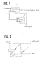
- a digital oscillation apparatus comprises an accumulating section 1 and a data generating section 2.
- the accumulating section 1 is responsive to a clock signal to accumulate a constant A and an output of the data generating section 2 clock by clock.
- an output waveform data as shown in FIG. 2 is obtained. That is, if the clock period be ⁇ , data increases by A at intervals of ⁇ , and when the data exceeds a dynamic range D, it overflows. As the result, a saw-tooth wave data is obtained.
- T D ⁇ /A (1)
- the frequency of the saw-tooth waveform can be changed.
- the accumulating section 2 operates in binary notation, and in such event, D becomes an exponentiation of two.
- D becomes an exponentiation of two.
- the data generating section 2 is provided to solve this problem, and functions as follows.
- the data generating section 2 periodically generates a data string a period of m clocks (m is integer), and the total of the data string in each period is R (R is integer).
- R is integer
- Eq. (3) can be also interpreted as follows.
- the accumulating section 3 comprises an adder 10 and a D-flip-flop 11 working as a delay circuit. Because the output of the adder 10 is delayed by one clock with the D-flip-flop 11 and returned to one input of the adder 10, the constant A inputted to another input of the adder 10 is accumulated every clock. The adder 10 overflows when the accumulated valve exceeds D.
- the adder 10 possesses a carry input, to which the output of the data generating section 4 is inputted.
- the data generating section 4 of this embodiment comprises an adder 5, an overflow detector 6, a switching circuit 8, a subtraction circuit 7, and a D-flip-flop 9.
- the adder 5 adds R to the output of the D flip-flop 9.
- the output of the adder 5 is checked by the overflow detector 6 if it exceeds m, and should it exceed m, the switching circuit 8 switches to its terminal 13 to subtract m from the output of the adder 5 with the subtractor 7.
- the output of the subtractor 7 is fed to the D-flip-flop 9.
- the output of the D flip-flop 9 is returned to the adder 5.
- the overflow detector 6 outputs "1" when detecting overflow and "0" otherwise to the carry input of the adder 10 in the accumulating section 3.
- the output data of the adder 5 has a cycle m, and the overflow detector 6 outputs "1" at the rate of R times to m times. Consequently, the average of m times of outputs of the overflow detector 6 becomes R/m, and adding this signal to the carry input of the adder 10 in the accumulating section 3 can produce equivalent effect to that of the first embodiment.
- the present embodiment is advantageous in that it can utilize the carry input of the adder 10 because the output of the data generating section 4 is either "0" or "1", that is, 1 bit.
- the third embodiment is described.
- the accumulating section 3 is the same as that of the second embodiment, while the data generating section 20 comprises an m-counter 22 and a ROM 21.
- the m-counter 22 divides the clock frequency by m.
- the data generating section 20 is a circuit to output "1" at the rate of R times to m times.
- the output of the m-counter 22 is given to the address input of ROM 21.
- ROM 21 stores "1" in R addresses out of m addresses, and "0" in the remaining m-R addresses. This allows the third embodiment to perform the same operation as the first embodiment.
- ROM 21 stores in advance a pattern to be obtained at the output of the data generating section 4 of the second embodiment, the third embodiment performs the same operation as the second embodiment.
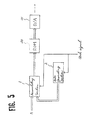
- FIG. 5 the fourth embodiment of the present invention is described.
- This embodiment is realized by adding a ROM 30 and a D/A converter 31 to the first embodiment.
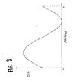
- the output waveform of the accumulating section 1 is saw-tooth waveform as shown in the first embodiments. Therefore, if sinusoidal data is stored in advance in ROM 30 as shown in FIG. 6 and the output data of the accumulating section 1 is fed to the address input of ROM 30, the output data of ROM 30 becomes a sinusoidal waveform data. It is possible to convert this data with the D/A converter 31 to an analog sine wave. Storing an optional waveform data other than sine wave in ROM 30 allows an optional waveform to be produced.
- FIG. 7 the fifth embodiment of the present invention is described.
- This embodiment is realized by adding a D/A converter 32 to the first embodiment, thereby providing an analog saw-tooth waveform.
Landscapes
- Engineering & Computer Science (AREA)
- General Physics & Mathematics (AREA)
- Theoretical Computer Science (AREA)
- Physics & Mathematics (AREA)
- Pure & Applied Mathematics (AREA)
- General Engineering & Computer Science (AREA)
- Computational Mathematics (AREA)
- Mathematical Analysis (AREA)
- Mathematical Optimization (AREA)
- Computing Systems (AREA)
- Mathematical Physics (AREA)
- Manipulation Of Pulses (AREA)
- Stabilization Of Oscillater, Synchronisation, Frequency Synthesizers (AREA)
- Electrophonic Musical Instruments (AREA)
Applications Claiming Priority (2)
| Application Number | Priority Date | Filing Date | Title |
|---|---|---|---|
| JP62257556A JPH0683067B2 (ja) | 1987-10-13 | 1987-10-13 | 分周装置 |
| JP257556/87 | 1987-10-13 |
Publications (3)
| Publication Number | Publication Date |
|---|---|
| EP0312370A2 true EP0312370A2 (de) | 1989-04-19 |
| EP0312370A3 EP0312370A3 (de) | 1991-03-20 |
| EP0312370B1 EP0312370B1 (de) | 1996-01-10 |
Family
ID=17307923
Family Applications (1)
| Application Number | Title | Priority Date | Filing Date |
|---|---|---|---|
| EP88309622A Expired - Lifetime EP0312370B1 (de) | 1987-10-13 | 1988-10-13 | Digitaloszillator |
Country Status (5)
| Country | Link |
|---|---|
| US (1) | US4959616A (de) |
| EP (1) | EP0312370B1 (de) |
| JP (1) | JPH0683067B2 (de) |
| KR (1) | KR910006473B1 (de) |
| DE (1) | DE3854887T2 (de) |
Cited By (8)
| Publication number | Priority date | Publication date | Assignee | Title |
|---|---|---|---|---|
| EP0443242A2 (de) * | 1990-02-20 | 1991-08-28 | John Fluke Mfg. Co., Inc. | Hochauflösender direkter digitaler Synthetisierer |
| EP0459446A1 (de) * | 1990-05-31 | 1991-12-04 | Sony Corporation | Digital gesteuerter Oszillator |
| EP0486851A2 (de) * | 1990-11-19 | 1992-05-27 | Tektronix Inc. | Direkter digitaler Synthetisierer mit rückgekoppeltem Schieberegister |
| EP0493057A1 (de) * | 1990-12-20 | 1992-07-01 | Motorola, Inc. | Synthetisierer mit höherer Frequenzauflösung |
| EP0599663A2 (de) * | 1992-11-27 | 1994-06-01 | Samsung Electronics Co., Ltd. | Chrominanzsignalverarbeitung |
| EP0604381A2 (de) * | 1992-12-22 | 1994-06-29 | Hughes Aircraft Company | FSK-Modulator, der eine nicht ganzzahlige Anzahl von Abtastwerten in jedem Symbolraum benutzt |
| EP1215558A2 (de) * | 2000-12-14 | 2002-06-19 | Nec Corporation | Verfahren und Schaltung zur Berechnung eines Vielfaches eines Einheitswertes und zum Erzeugen einer periodischen Funktion |
| EP1550934A1 (de) * | 2003-12-29 | 2005-07-06 | Teradyne, Inc. | Mehrstufiger numerisch gesteuerter Oszillator |
Families Citing this family (4)
| Publication number | Priority date | Publication date | Assignee | Title |
|---|---|---|---|---|
| US5638010A (en) * | 1995-06-07 | 1997-06-10 | Analog Devices, Inc. | Digitally controlled oscillator for a phase-locked loop providing a residue signal for use in continuously variable interpolation and decimation filters |
| FR2757001B1 (fr) * | 1996-12-05 | 1999-02-05 | Sgs Thomson Microelectronics | Dispositif de decoupage de la periode d'un signal en n parties quasi-egales |
| CN1797955B (zh) * | 2004-12-29 | 2011-08-24 | 泰拉丁公司 | 多级数字计数振荡器 |
| US7944251B2 (en) * | 2009-03-09 | 2011-05-17 | Broadcom Corporation | Reduced line driver output dependency on process, voltage, and temperature variations |
Citations (1)
| Publication number | Priority date | Publication date | Assignee | Title |
|---|---|---|---|---|
| US4492936A (en) * | 1981-08-17 | 1985-01-08 | Thomson-Csf | Fractional-division frequency synthesizer for digital angle-modulation |
Family Cites Families (11)
| Publication number | Priority date | Publication date | Assignee | Title |
|---|---|---|---|---|
| US2858434A (en) * | 1956-09-25 | 1958-10-28 | Collins Radio Co | Precision step voltage generator |
| US3121803A (en) * | 1959-05-28 | 1964-02-18 | Zenith Radio Corp | Stair-step counter with pulse storage capacitor triggering, via anti-leakage diode, transistor blocking oscillator |
| US3657657A (en) * | 1970-08-03 | 1972-04-18 | William T Jefferson | Digital sine wave generator |
| US3919649A (en) * | 1973-10-31 | 1975-11-11 | Rca Corp | Staircase waveform generator |
| JPS58165416A (ja) * | 1982-03-26 | 1983-09-30 | Hitachi Ltd | 可変段数階段波発生回路 |
| JPS58181315A (ja) * | 1982-04-16 | 1983-10-24 | Nec Corp | 階段波発生回路 |
| GB8432552D0 (en) * | 1984-12-21 | 1985-02-06 | Plessey Co Plc | Control circuits |
| GB2177862B (en) * | 1985-07-09 | 1989-07-19 | Motorola Inc | Waveform generators |
| JPS62150922A (ja) * | 1985-12-24 | 1987-07-04 | Matsushita Electric Ind Co Ltd | デジタル発振装置 |
| US4737720A (en) * | 1986-01-06 | 1988-04-12 | General Electric Company | DTMF generation using pre-summed tables |
| US4804863A (en) * | 1986-11-12 | 1989-02-14 | Crystal Semiconductor Corporation | Method and circuitry for generating reference voltages |
-
1987
- 1987-10-13 JP JP62257556A patent/JPH0683067B2/ja not_active Expired - Fee Related
-
1988
- 1988-10-11 US US07/255,267 patent/US4959616A/en not_active Expired - Lifetime
- 1988-10-12 KR KR1019880013296A patent/KR910006473B1/ko not_active IP Right Cessation
- 1988-10-13 EP EP88309622A patent/EP0312370B1/de not_active Expired - Lifetime
- 1988-10-13 DE DE3854887T patent/DE3854887T2/de not_active Expired - Fee Related
Patent Citations (1)
| Publication number | Priority date | Publication date | Assignee | Title |
|---|---|---|---|---|
| US4492936A (en) * | 1981-08-17 | 1985-01-08 | Thomson-Csf | Fractional-division frequency synthesizer for digital angle-modulation |
Non-Patent Citations (2)
| Title |
|---|
| ELEKTRONIK, vol. 32, no. 17, August 1983, pages 51-52, Munich, DE; J. RISCHEWSKI: "Digitaler Funktionsgenerator" * |
| IBM TECHNICAL DISCLOSURE BULLETIN, vol. 22, no. 3, August 1979, pages 975-978, New York, US; J.E. SCHWAGER et al.: "Acoustic interactive synthesizer" * |
Cited By (16)
| Publication number | Priority date | Publication date | Assignee | Title |
|---|---|---|---|---|
| EP0443242A3 (en) * | 1990-02-20 | 1992-11-19 | John Fluke Mfg. Co., Inc. | High resolution direct digital synthesizer |
| EP0443242A2 (de) * | 1990-02-20 | 1991-08-28 | John Fluke Mfg. Co., Inc. | Hochauflösender direkter digitaler Synthetisierer |
| EP0459446A1 (de) * | 1990-05-31 | 1991-12-04 | Sony Corporation | Digital gesteuerter Oszillator |
| US5153526A (en) * | 1990-05-31 | 1992-10-06 | Sony Corporation | Numerical control type oscillator apparatus |
| EP0486851A2 (de) * | 1990-11-19 | 1992-05-27 | Tektronix Inc. | Direkter digitaler Synthetisierer mit rückgekoppeltem Schieberegister |
| EP0486851A3 (en) * | 1990-11-19 | 1993-04-07 | Tektronix Inc. | Direct digital synthesizer with feedback shift register |
| EP0493057A1 (de) * | 1990-12-20 | 1992-07-01 | Motorola, Inc. | Synthetisierer mit höherer Frequenzauflösung |
| EP0599663A3 (de) * | 1992-11-27 | 1995-01-18 | Samsung Electronics Co Ltd | Chrominanzsignalverarbeitung. |
| EP0599663A2 (de) * | 1992-11-27 | 1994-06-01 | Samsung Electronics Co., Ltd. | Chrominanzsignalverarbeitung |
| EP0604381A2 (de) * | 1992-12-22 | 1994-06-29 | Hughes Aircraft Company | FSK-Modulator, der eine nicht ganzzahlige Anzahl von Abtastwerten in jedem Symbolraum benutzt |
| EP0604381A3 (de) * | 1992-12-22 | 1994-07-27 | Hughes Aircraft Company | FSK-Modulator, der eine nicht ganzzahlige Anzahl von Abtastwerten in jedem Symbolraum benutzt |
| EP1215558A2 (de) * | 2000-12-14 | 2002-06-19 | Nec Corporation | Verfahren und Schaltung zur Berechnung eines Vielfaches eines Einheitswertes und zum Erzeugen einer periodischen Funktion |
| EP1215558A3 (de) * | 2000-12-14 | 2005-03-30 | NEC Electronics Corporation | Verfahren und Schaltung zur Berechnung eines Vielfaches eines Einheitswertes und zum Erzeugen einer periodischen Funktion |
| US7069283B2 (en) | 2000-12-14 | 2006-06-27 | Nec Electronics Corporation | Method and circuit for calculating multiple of unit value and generating a periodic function |
| EP1550934A1 (de) * | 2003-12-29 | 2005-07-06 | Teradyne, Inc. | Mehrstufiger numerisch gesteuerter Oszillator |
| US7064616B2 (en) | 2003-12-29 | 2006-06-20 | Teradyne, Inc. | Multi-stage numeric counter oscillator |
Also Published As
| Publication number | Publication date |
|---|---|
| DE3854887T2 (de) | 1996-08-14 |
| JPH0683067B2 (ja) | 1994-10-19 |
| DE3854887D1 (de) | 1996-02-22 |
| EP0312370A3 (de) | 1991-03-20 |
| KR910006473B1 (ko) | 1991-08-26 |
| US4959616A (en) | 1990-09-25 |
| KR890007499A (ko) | 1989-06-20 |
| JPH0199322A (ja) | 1989-04-18 |
| EP0312370B1 (de) | 1996-01-10 |
Similar Documents
| Publication | Publication Date | Title |
|---|---|---|
| US4998072A (en) | High resolution direct digital synthesizer | |
| EP0312370A2 (de) | Digitaloszillator | |
| KR930001296B1 (ko) | 보간용 시간이산 필터장치 | |
| US3997773A (en) | Interpolating digital filter with input buffer | |
| US4972360A (en) | Digital filter for a modem sigma-delta analog-to-digital converter | |
| KR900009194B1 (ko) | 데시메이션 필터 장치 | |
| EP0158538B1 (de) | Verfahren und Schaltung zur Erzeugung eines zeitvariablen Signals | |
| US5329260A (en) | Numerically-controlled modulated oscillator and modulation method | |
| EP0782062B1 (de) | Rauschverminderung in digitalen Frequenzsynthetisierern | |
| KR970012132A (ko) | 곱-합 계산 장치, 곱-합 계산 장치의 집적 회로 장치, 및 영상 데이타를 처리하기에 적절한 누적 가산기 | |
| US5521534A (en) | Numerically controlled oscillator for generating a digitally represented sine wave output signal | |
| US5619535A (en) | Digital frequency synthesizer | |
| JPH0783267B2 (ja) | 2進信号をこれに比例する直流信号に変換する装置 | |
| EP0527660B1 (de) | Digitaler Frequenzmodulator | |
| EP1357460B1 (de) | Ein numerisch gesteuerter Oszillator (NCO) zur Erzeugung von Frequenzen mit rationalem Teilervehältnis | |
| US4766416A (en) | Circuit for generating the square of a function without multipliers | |
| US5838956A (en) | Clock generating circuit | |
| US4485717A (en) | Electronic musical instrument | |
| RU2239281C2 (ru) | Цифровой синтезатор гармонических колебаний | |
| SU813679A1 (ru) | Цифровой синтезатор частот | |
| SU726535A1 (ru) | Устройство дл решени систем линейных дифференциальных уравнений | |
| KR0164508B1 (ko) | 병렬 처리용 최고값 검출회로 | |
| RU2237972C2 (ru) | Синтезатор частоты | |
| SU739558A1 (ru) | Функциональный преобразователь с кусочно-линейной аппроксимацией | |
| SU1109734A2 (ru) | Преобразователь комплексных чисел в двоичный код |
Legal Events
| Date | Code | Title | Description |
|---|---|---|---|
| PUAI | Public reference made under article 153(3) epc to a published international application that has entered the european phase |
Free format text: ORIGINAL CODE: 0009012 |
|
| AK | Designated contracting states |
Kind code of ref document: A2 Designated state(s): DE FR GB NL |
|
| PUAL | Search report despatched |
Free format text: ORIGINAL CODE: 0009013 |
|
| AK | Designated contracting states |
Kind code of ref document: A3 Designated state(s): DE FR GB NL |
|
| 17P | Request for examination filed |
Effective date: 19910917 |
|
| 17Q | First examination report despatched |
Effective date: 19940310 |
|
| GRAA | (expected) grant |
Free format text: ORIGINAL CODE: 0009210 |
|
| AK | Designated contracting states |
Kind code of ref document: B1 Designated state(s): DE FR GB NL |
|
| REF | Corresponds to: |
Ref document number: 3854887 Country of ref document: DE Date of ref document: 19960222 |
|
| ET | Fr: translation filed | ||
| PLBE | No opposition filed within time limit |
Free format text: ORIGINAL CODE: 0009261 |
|
| STAA | Information on the status of an ep patent application or granted ep patent |
Free format text: STATUS: NO OPPOSITION FILED WITHIN TIME LIMIT |
|
| 26N | No opposition filed | ||
| REG | Reference to a national code |
Ref country code: GB Ref legal event code: IF02 |
|
| REG | Reference to a national code |
Ref country code: GB Ref legal event code: 746 Effective date: 20031002 |
|
| REG | Reference to a national code |
Ref country code: FR Ref legal event code: D6 |
|
| PGFP | Annual fee paid to national office [announced via postgrant information from national office to epo] |
Ref country code: DE Payment date: 20051006 Year of fee payment: 18 |
|
| PGFP | Annual fee paid to national office [announced via postgrant information from national office to epo] |
Ref country code: FR Payment date: 20051010 Year of fee payment: 18 |
|
| PGFP | Annual fee paid to national office [announced via postgrant information from national office to epo] |
Ref country code: GB Payment date: 20051012 Year of fee payment: 18 |
|
| PGFP | Annual fee paid to national office [announced via postgrant information from national office to epo] |
Ref country code: NL Payment date: 20051016 Year of fee payment: 18 |
|
| PG25 | Lapsed in a contracting state [announced via postgrant information from national office to epo] |
Ref country code: NL Free format text: LAPSE BECAUSE OF NON-PAYMENT OF DUE FEES Effective date: 20070501 Ref country code: DE Free format text: LAPSE BECAUSE OF NON-PAYMENT OF DUE FEES Effective date: 20070501 |
|
| GBPC | Gb: european patent ceased through non-payment of renewal fee |
Effective date: 20061013 |
|
| NLV4 | Nl: lapsed or anulled due to non-payment of the annual fee |
Effective date: 20070501 |
|
| REG | Reference to a national code |
Ref country code: FR Ref legal event code: ST Effective date: 20070629 |
|
| PG25 | Lapsed in a contracting state [announced via postgrant information from national office to epo] |
Ref country code: GB Free format text: LAPSE BECAUSE OF NON-PAYMENT OF DUE FEES Effective date: 20061013 |
|
| PG25 | Lapsed in a contracting state [announced via postgrant information from national office to epo] |
Ref country code: FR Free format text: LAPSE BECAUSE OF NON-PAYMENT OF DUE FEES Effective date: 20061031 |