EP0312230A2 - Bilderzeugungsgerät - Google Patents
Bilderzeugungsgerät Download PDFInfo
- Publication number
- EP0312230A2 EP0312230A2 EP88309163A EP88309163A EP0312230A2 EP 0312230 A2 EP0312230 A2 EP 0312230A2 EP 88309163 A EP88309163 A EP 88309163A EP 88309163 A EP88309163 A EP 88309163A EP 0312230 A2 EP0312230 A2 EP 0312230A2
- Authority
- EP
- European Patent Office
- Prior art keywords
- blade
- charging
- image bearing
- photosensitive member
- bearing member
- Prior art date
- Legal status (The legal status is an assumption and is not a legal conclusion. Google has not performed a legal analysis and makes no representation as to the accuracy of the status listed.)
- Granted
Links
Images

Classifications
-
- G—PHYSICS
- G03—PHOTOGRAPHY; CINEMATOGRAPHY; ANALOGOUS TECHNIQUES USING WAVES OTHER THAN OPTICAL WAVES; ELECTROGRAPHY; HOLOGRAPHY
- G03G—ELECTROGRAPHY; ELECTROPHOTOGRAPHY; MAGNETOGRAPHY
- G03G21/00—Arrangements not provided for by groups G03G13/00 - G03G19/00, e.g. cleaning, elimination of residual charge
- G03G21/16—Mechanical means for facilitating the maintenance of the apparatus, e.g. modular arrangements
- G03G21/18—Mechanical means for facilitating the maintenance of the apparatus, e.g. modular arrangements using a processing cartridge, whereby the process cartridge comprises at least two image processing means in a single unit
- G03G21/1803—Arrangements or disposition of the complete process cartridge or parts thereof
- G03G21/1814—Details of parts of process cartridge, e.g. for charging, transfer, cleaning, developing
-
- G—PHYSICS
- G03—PHOTOGRAPHY; CINEMATOGRAPHY; ANALOGOUS TECHNIQUES USING WAVES OTHER THAN OPTICAL WAVES; ELECTROGRAPHY; HOLOGRAPHY
- G03G—ELECTROGRAPHY; ELECTROPHOTOGRAPHY; MAGNETOGRAPHY
- G03G15/00—Apparatus for electrographic processes using a charge pattern
- G03G15/02—Apparatus for electrographic processes using a charge pattern for laying down a uniform charge, e.g. for sensitising; Corona discharge devices
- G03G15/0208—Apparatus for electrographic processes using a charge pattern for laying down a uniform charge, e.g. for sensitising; Corona discharge devices by contact, friction or induction, e.g. liquid charging apparatus
- G03G15/0216—Apparatus for electrographic processes using a charge pattern for laying down a uniform charge, e.g. for sensitising; Corona discharge devices by contact, friction or induction, e.g. liquid charging apparatus by bringing a charging member into contact with the member to be charged, e.g. roller, brush chargers
-
- G—PHYSICS
- G03—PHOTOGRAPHY; CINEMATOGRAPHY; ANALOGOUS TECHNIQUES USING WAVES OTHER THAN OPTICAL WAVES; ELECTROGRAPHY; HOLOGRAPHY
- G03G—ELECTROGRAPHY; ELECTROPHOTOGRAPHY; MAGNETOGRAPHY
- G03G21/00—Arrangements not provided for by groups G03G13/00 - G03G19/00, e.g. cleaning, elimination of residual charge
- G03G21/0005—Arrangements not provided for by groups G03G13/00 - G03G19/00, e.g. cleaning, elimination of residual charge for removing solid developer or debris from the electrographic recording medium
- G03G21/0011—Arrangements not provided for by groups G03G13/00 - G03G19/00, e.g. cleaning, elimination of residual charge for removing solid developer or debris from the electrographic recording medium using a blade; Details of cleaning blades, e.g. blade shape, layer forming
-
- G—PHYSICS
- G03—PHOTOGRAPHY; CINEMATOGRAPHY; ANALOGOUS TECHNIQUES USING WAVES OTHER THAN OPTICAL WAVES; ELECTROGRAPHY; HOLOGRAPHY
- G03G—ELECTROGRAPHY; ELECTROPHOTOGRAPHY; MAGNETOGRAPHY
- G03G2221/00—Processes not provided for by group G03G2215/00, e.g. cleaning or residual charge elimination
- G03G2221/16—Mechanical means for facilitating the maintenance of the apparatus, e.g. modular arrangements and complete machine concepts
- G03G2221/1618—Mechanical means for facilitating the maintenance of the apparatus, e.g. modular arrangements and complete machine concepts for the cleaning unit
-
- G—PHYSICS
- G03—PHOTOGRAPHY; CINEMATOGRAPHY; ANALOGOUS TECHNIQUES USING WAVES OTHER THAN OPTICAL WAVES; ELECTROGRAPHY; HOLOGRAPHY
- G03G—ELECTROGRAPHY; ELECTROPHOTOGRAPHY; MAGNETOGRAPHY
- G03G2221/00—Processes not provided for by group G03G2215/00, e.g. cleaning or residual charge elimination
- G03G2221/16—Mechanical means for facilitating the maintenance of the apparatus, e.g. modular arrangements and complete machine concepts
- G03G2221/1651—Mechanical means for facilitating the maintenance of the apparatus, e.g. modular arrangements and complete machine concepts for connecting the different parts
- G03G2221/1654—Locks and means for positioning or alignment
-
- G—PHYSICS
- G03—PHOTOGRAPHY; CINEMATOGRAPHY; ANALOGOUS TECHNIQUES USING WAVES OTHER THAN OPTICAL WAVES; ELECTROGRAPHY; HOLOGRAPHY
- G03G—ELECTROGRAPHY; ELECTROPHOTOGRAPHY; MAGNETOGRAPHY
- G03G2221/00—Processes not provided for by group G03G2215/00, e.g. cleaning or residual charge elimination
- G03G2221/16—Mechanical means for facilitating the maintenance of the apparatus, e.g. modular arrangements and complete machine concepts
- G03G2221/1669—Details about used materials
-
- G—PHYSICS
- G03—PHOTOGRAPHY; CINEMATOGRAPHY; ANALOGOUS TECHNIQUES USING WAVES OTHER THAN OPTICAL WAVES; ELECTROGRAPHY; HOLOGRAPHY
- G03G—ELECTROGRAPHY; ELECTROPHOTOGRAPHY; MAGNETOGRAPHY
- G03G2221/00—Processes not provided for by group G03G2215/00, e.g. cleaning or residual charge elimination
- G03G2221/16—Mechanical means for facilitating the maintenance of the apparatus, e.g. modular arrangements and complete machine concepts
- G03G2221/1693—Mechanical means for facilitating the maintenance of the apparatus, e.g. modular arrangements and complete machine concepts for charging
-
- G—PHYSICS
- G03—PHOTOGRAPHY; CINEMATOGRAPHY; ANALOGOUS TECHNIQUES USING WAVES OTHER THAN OPTICAL WAVES; ELECTROGRAPHY; HOLOGRAPHY
- G03G—ELECTROGRAPHY; ELECTROPHOTOGRAPHY; MAGNETOGRAPHY
- G03G2221/00—Processes not provided for by group G03G2215/00, e.g. cleaning or residual charge elimination
- G03G2221/16—Mechanical means for facilitating the maintenance of the apparatus, e.g. modular arrangements and complete machine concepts
- G03G2221/18—Cartridge systems
- G03G2221/183—Process cartridge
Definitions
- the present invention relates to an image forming apparatus such as an electrophotographic copying machine and a laser beam printer, more particularly to an image forming apparatus wherein an image is formed on a movable image bearing surface by image forming means including means for charging the surface of the image bearing member, and wherein the surface of the image bearing member is cleaned by cleaning means and is used for repetitive image formation.
- an image forming apparatus of such a type there is an electrophotographic copying machine or an electrostatic recording apparatus of an image transfer type.
- an electrophotographic photosensitive member in the form of a drum or an endless belt which is rotated is used as the image bearing member.
- a visualized image is formed by image forming means through a process including essentially uniform charging, an image exposure and a development, and the visualized image is transferred onto a surface of a transfer material by image transfer means.
- the transferred image is fixed on the surface of the transfer material by an image fixing means.
- the transfer material is discharged as a print on which an image has been formed.
- the surface of the photosensitive member, after the image has been transferred therefrom, is cleaned by cleaning means and is repeatedly used for image formation.
- the electrostatic recording apparatus of the image transfer type uses a dielectric member in the form of a drum or an endless belt which is rotated as the image bearing member.
- a visualized image is formed on the surface of the dielectric member by image forming means through a process including essentially uniform, selective discharge and development.
- the visualized image is transferred onto the surface of the transfer material and is fixed thereon.
- the transfer material is discharged as a print having an image.
- the surface of the dielectric member, after the image is transferred therefrom, is cleaned by a cleaning means for repetitive use for image formation.
- the cleaning means is to remove untransferred developer (toner), paper dust produced from the transfer material and other deposited foreign matter which remain on the surface of the photosensitive member or the dielectric member after the image is transferred onto the surface of the transfer material.
- the cleaning means includes an elastic member such as urethane rubber which is contacted to the surface of the image bearing member to remove the foreign matter.
- a corona discharger such as a corotron and a scorotron provided with a wire electrode and a shield electrode is widely used since it is good in uniformness of charging.
- the corona discharger involves various problems. First, it requires an expensive high voltage source, a large space due to the structure of itself and the shielding space for the high voltage source. Also, it produces a relatively large amount of corona production such as ozone, and therefore, it requires additional means and mechanism for dealing with the production, which results in bulkiness and expensiveness of the apparatus.
- the contact type charging device includes a conductive member (contactable charging member) which is supplied from a power source with a voltage which is a DC voltage of approximately 1 - 2 KV, for example, or an superimposed DC and AC voltage, and is contacted to the image bearing member surface which is a member to be charged, by which the image bearing member is charged to a predetermined potential.
- a roller type charger U.S. Patent No. 4,387,980
- a blade type charger a brush type charger and a charging and cleaning device
- the charging member is contacted to the image bearing member uniformly along the length thereof, and if the contact is not uniform, the image bearing member surface is non-uniformly charged.
- the non-uniform charging can occur due to the developer, the paper dust and other foreign matter which are removed from the surface of the image bearing member after the image transfer and which are accumulated in the charging portion.
- the image forming apparatus is of a type wherein a dismountable process cartridge is used, foreign matter is sometimes introduced into the charging region by vibration produced upon mounting and dismounting operation of the process cartridge and produced when the process cartridge is carried around.
- the blade type charger is preferable as disclosed in Japanese Laid-Open Patent Application 150,975/1983 and U.S. Patent No. 4,387,980.
- the blade type charging member can involve a problem that the surface of the image bearing member is worn or damaged or that the charging member or the cleaning member is burred, with the result of non-uniform charge.
- an image forming apparatus including a contact type charger for charging a surface of an image bearing member, and wherein the surface of the image bearing member can be uniformly charged.
- the contact between the image bearing member surface and the contact type charging member are uniformly contacted along the length thereof to uniformly charge the image bearing member.
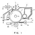
- FIG. 1 there is shown an image forming apparatus according to an embodiment of the present invention, wherein the image forming apparatus is illustrated as an image transfer type electrophotographic copying apparatus which is used with a process cartridge.
- the image forming apparatus comprises an electrophotographic photosensitive member in the form of a drum, which will hereinafter be called "photosensitive member".
- the photosensitive member 1 functions as an image bearing member and is driven to rotate at a predetermined peripheral speed in the direction indicated by an arrow about a shaft 1a.
- a contact type charging member 2 for uniformly charging a peripheral surface of the photosensitive member 1 is made of an electrically conductive elastic blade such as a conductive rubber blade which may be provided at its outer surface with a resistance layer having an appropriate resistance (a volume resistivity of 108-1012 ohm.cm, for example).
- the image forming apparatus comprises an array of short focus lenses as light image exposure means, a developing device 4, an image transfer device 5 a timing roller 51 for introducing a transfer material P fed one by one from an unshown feeding station into the clearance between the photosensitive member 1 and the transfer device 5 in synchronization with the rotation of the photosensitive member 1, and a transfer material guiding member 52 disposed between the timing roller 51 and the transfer device 5.
- the apparatus further comprises a conveying device 52 for conveying into an image fixing device not shown, the transfer material P having received an image passing through the clearance between the photosensitive member 1 and the transfer device 5, and a cleaning device 6 for cleaning the surface of the photosensitive member 1 after the image is transferred.
- the photosensitive member 1, the contact charging member 2, the developing device 4 and the cleaning device 6 are constituted as a process cartridge 7 wherein they are built in in predetermined positional relationships.
- the process cartridge 7 may contain at least the contact type charging member 2 and the cleaning device 6.
- the process cartridge 7 is inserted into the main assembly of the copying apparatus along supporting rails 8 and 8 in the direction perpendicular to the sheet of the drawing of Figure 1, or may be retracted out of the main apparatus.
- the process cartridge 7 and the main assembly of the copying apparatus are mechanically and electrically coupled to become operative as a copying system.
- the peripheral surface of the photosensitive member 1 is uniformly charged by the blade 2 functioning as a contact charging member supplied with a voltage (a superposed DC and AC voltage, for example) from a power source E, and then is subjected to image light (slit exposure to an original image) when passing by the light image exposure means 3, by which an electrostatic latent image is sequentially formed thereon, corresponding to the pattern of the exposure.
- Designated by a reference 7a is a light passing opening formed in a cartridge housing wall in opposition to the light image exposure means 3.
- the light image exposure may be performed with the use of a scanning laser beam.
- a latent image is sequentially formed on the image bearing member by means such as an array of electrodes for selectively discharging the image bearing member.
- the latent image formed on the surface of the photosensitive member is sequentially developed or visualized as a toner image sequentially by the developing device 4.
- the transfer material P is singled out of an unshown sheet feeding station and is fed into the clearance between the transfer device 5 and the photosensitive member 1 in timed relation with the rotation of the photosensitive member 1 by the timing roller 51.
- the visualized image on the photosensitive member 1 is transferred onto a surface of the transfer material P.
- the transfer material P having received the image by passing through the transfer station 5 is sequentially separated from the surface of the photosensitive member 1 and is transported by a conveying device 53 to an unshown image fixing device, where the image is fixed on the transfer material P, and it is discharged as a print.
- the surface of the photosensitive member 1, after the image is transferred, is cleaned by a cleaning member 6A of the cleaning device 6, so that the residual toner thereon, the paper dust produced from the transfer material and other foreign matter are removed so as to be prepared for next image forming operation.
- the cleaning member 6A in this embodiment includes a scraper blade, which will hereinafter be called “cleaning blade”, made of urethane rubber or the like, contacted to the surface of the photosensitive member 1 at its edge.
- the cleaning blade 6A functions to scrape the residual matter off the surface of the photosensitive member 1.
- the contact friction force in relation to the photosensitive member 1 is large, so that the cleaning blade 6A receives a strong burring force (a force tending to turn up the edge of the cleaning blade) so that the edge of the blade is easily burred.
- the residual matter such as the developer removed from the photosensitive member 1 surface is present at the contact area between the cleaning blade 6A and the photosensitive member 1 and functions as a lubricant to reduce the dynamic friction coefficient to prevent the blade from burring.
- the contact charging blade 2 is contacted to the surface of the photosensitive member 1 which has been cleaned by the cleaning blade 6A, and therefore, the lubricating function of the residual matter as in the case of the cleaning blade 6A is not provided, so that the blade is in the state of being easily burred.
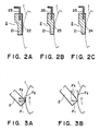
- Figure 3B shows the relation among the burring forces, wherein F1 is a force necessary for pressing the contact charging blade to the photosensitive member 1 surface for uniform charging, F2 is a frictional force resulting from the pressing force of the contact charging blade 2 to the photosensitive member 1 when the surface of the photosensitive member is moved, and F3 is a resultant force thereof.
- the friction force F2 is ⁇ F1, where the friction coefficient is ⁇ .
- the resultant force F3 is such as to burr the edge of the blade 2, and the force F2 increases with increase of the friction coefficient, so that the burring force increases.
- FIGS. 2A, 2B and 2C there are shown examples of structures for reducing the frictional coefficient of the blade 2 relative to the photosensitive member 1.
- the contact charging blade 2 is provided with a conductive rubber blade portion 21 in which the resistance is controlled.
- the voltage is applied to the blade portion 21 through the conductive support 25.
- that side of the blade portion 21 which is faced to the photosensitive member 1 is provided with a sheet layer 22, attached thereto, which is made of a low friction coefficient material and which has better parting properties than rubber.
- the sheet layer 22 is made, in this example, of a resin such as nylon or PFA resin having good lubricating property, containing electrically conductive material to control electric resistance. By the sheet layer 22, the frictional coefficient of the contact charging blade 2 is reduced.
- the blade portion 21 may have a low resistance.
- the thickness of the sheet layer 22 is large, the charging performance is not good, and therefore, the thickness of the sheet layer 22 is preferably as small as possible.
- the conductive rubber blade portion 21 which is the main body is molded.
- the molding surface is finely roughened so that the surface of the blade portion 21 faced to the photosensitive member has a finely roughened surface 23, by which the effective contact area between the photosensitive member and the blade portion 21 is reduced to reduce the frictional coefficient.
- the conductive rubber blade portion 21 which is the main body is molded.
- a parting agent remains on the surface of the molded blade.
- the parting agent has been applied on the molding surface during the molding process, and is silicone or fluorine oil type parting agent.
- the parting agent on that surface of the blade portion which is faced to the photosensitive member, at least, is not removed and remained, as shown by the reference numeral 24.
- the lubricating property of the parting agent is utilized to reduce the frictional coefficient of the blade with respect to the photosensitive member.
- the peak-to-peak voltage of a vibratory voltage applied to the charging blade is preferably not less than twice the absolute value of the charging starting voltage when only a DC voltage is applied as disclosed in U.S. Serial No. 131,585 and U.S. Serial No. 159,917.
- the vibratory voltage is a voltage which periodically change with time, and the waveform may be sine, triangular, rectangular or the like form.
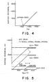
- the charge starting voltage is determined in the following manner.
- the charging member is contacted to a member to be charged having a surface potential of zero, and only a DC voltage is applied to the charging member.
- the DC voltage is increased, and the surface potential of the member to be charged is plotted in the surface potential vs. applied voltage graph.
- the voltages are plotted with increment of 100 V.
- the first plot of the voltage is the one which the surface potential of the member to be charged appears, and ten surface potentials are plotted at each 100 V increment.
- a straight line is drawn from the plots.
- the DC voltage leading at which the straight line and the line representing the zero surface potential crosses is deemed as the charge starting voltage.
- Figure 4 is a graph illustrating an example of the above method.
- the charge starting voltage was -560 V in this embodiment.
- V DC -750, -500, -100 V.
- the photosensitive member 1 was an OPC photosensitive member.
- the cleaning blade 6A was made of a urethane rubber (65 degrees JIS A). The cleaning blade 6A was press contacted to the photosensitive member 1 under a pressure of 11 - 35 g/cm.
- the contact charging blade 2 included a conductive EPDM rubber blade 21 having the volume resistivity of 102 - 106 ohm.cm and a lubricating coating layer 22 made of a nylon resin having the volume resistivity of 108 ohm.cm. The charging blade was press contacted to the photosensitive member under the pressure of 5 - 20 g/cm.
- the blade 2 was supplied with a bias voltage which is a vibratory voltage provided by superposing a DC voltage of 700 V and an AC voltage having a peak-to-peak voltage Vpp of 1500 V and a frequency of 800 Hz.
- the surface potential provided on the photosensitive member was approximately 700 V.
- the blade was burred, or the photosensitive member was damaged after 1000 sheets were processed. On the contrary, with the lubricating coating layer 22, the blade was not burred, and the photosensitive member is not damaged even after 3000 sheets were processed.
- the contact angle of the charging blade relative to the image bearing member is smaller than the contact angle of the cleaning blade relative to the image bearing member.
- the contact angle of the blade relative to the image bearing member is defined as an angle formed between a tangent line of the image bearing member at the point of contact between the blade and the image bearing member and a line extending between an edge contact point of the blade to the image bearing member and a point 2 mm away from the edge contact point along the surface of the blade toward a blade support.
- Figure 10 illustrates the contact angle as defined above.
- the description will be made as to the relation between the contact angle of the charging blade relative to the image bearing member and the contact angle of the cleaning blade relative to the image bearing member.
- the cleaning blade 6A is imparted by a pressure necessary for removing the residual matter t ( Figure 2) from the surface of the photosensitive member 1.
- the contact angle ⁇ 1 of the cleaning blade 6A relative to the photosensitive member 1 is formed at the downstream side of the contact between the cleaning blade and the photosensitive member with respect to the moving direction of the photosensitive member surface, and is such that the cleaning blade surface is not contacted to the photo-sensitive member at its an antinoding side.
- the contacting edge of the cleaning blade 6A tends to turn up, that is, to burr toward the movement of the photosensitive member 1 surface by the friction with the photosensitive member 1, and the tendency is stronger with increase of the angle ⁇ 1.
- the angle ⁇ 1 is relatively large, the residual matter t removed from the surface of the photosensitive member 1 is present in the area of contact between the cleaning blade 6A and the photosensitive member 1, and the residual matter functions as a lubricant to reduce the dynamic frictional coefficient to prevent the cleaning blade 6A from burring. In other words, the permissible range of the contact angle ⁇ 1 is enlarged.
- the contact angle ⁇ 2 of the contact charging blade 2 relative to the photosensitive member which is smaller than 90 degrees, is formed at such as side as is downstream of the point of contact therebetween with respect to the movement direction of the surface of the photosensitive member.
- the cleaning blade 6 and the charging blade 2 are counter-directionally disposed relative to the photosensitive member.
- the blade 2 As contrasted to the cleaning blade 6A, there is no residual matter functioning as the lubricant, at the point of contact between the charging blade 2 and the photosensitive member 1 surface. For this reason, the blade is more easily burred, and it depends on the contact angle ⁇ 2 of the blade 2 relative to the photosensitive member 1.
- the contact angle ⁇ 2 of the charging blade 2 relative to the photosensitive member is as small as possible.
- the small contact angle ⁇ 2 is also effective to make the charging uniform.
- the contact angle ⁇ 2 of the contact charging blade 2 relative to the photosensitive member is smaller than the contact angle ⁇ 1 of the cleaning blade relative to the photosensitive member ( ⁇ 2 ⁇ ⁇ 1), by which the cleaning blade 6A is not contacted to the photosensitive member 1 at its antinoding side to ensure good cleaning properties, and simultaneously, the contact charging blade is not burred with the uniform and stabilized charging property ensured.
- the contact angle ⁇ 2 is not less than the contact angle ⁇ 1 ( ⁇ 2 ⁇ ⁇ 1), the contact charging blade 2 is more easily burred with increase of the contact angle ⁇ 2 beyond the contact angle ⁇ 1, and the uniform charging is not provided to practicable extent.
- the charging properties and the cleaning properties were investigated through experiments.
- the charging blade and the cleaning blade were made of polyester urethane rubber having a hardness of 65 degrees (JIS A), and they each had a thickness of 2 mm and free portion length of 10 mm.
- the contact angle to the photosensitive member was changed.
- Table 1 CHARGING BLADE CONTACT ANGLE VS.
- CLEANING PROPERTY OPC PHOTOSENSITIVE MEMBER
- CLEANING PROPERTY A-Si PHOTOSENSITIVE MEMBER
- CLEANING PROPERTY A-Si PHOTOSENSITIVE MEMBER
- the blades were counter-directionally contacted with respect to the moving direction of the surface of the photosensitive member.
- the charging properties and the cleaning properties are evaluated on the basis of the final image when they were incorporated in an electrophotographic copying machine.
- G indicates that the charging properties and the cleaning properties are good, and the final image is good enough;
- F indicates that the final image involves a little problem arising from the charging properties and the cleaning properties, but it is practically good;
- N indicates that the final image involves problems arising from the charging properties and the cleaning properties, and it is not practically usable.
- the charging properties are "N” when the final image includes spots, while the cleaning properties are "N” when a stripe or stripes are produced on the image in the direction of the photosensitive member movement. These are easily observed when a solid black image is formed, in the case of a regular development.
- the charging and cleaning properties are deemed “G” when good images are provided even after 3000 copies are produced.
- the charging properties were not influenced by materials of the photosensitive member.
- the experiments were conducted in the following step. At first, the contact angle of the charging blade ⁇ 2 was fixed 0 degrees, whereas the contact angle ⁇ 1 of the cleaning blade is changed in the range of 10 - 50 degrees, and the charging and cleaning properties were investigated. Next, the contact angle ⁇ 2 was increased with increment of 5 degrees, and the contact angle ⁇ 1 was changed in the range of 10 - 50 degrees for each incremented angles, and the charging and cleaning properties were investigated. It was confirmed that the charging blade is practically usable when the contact angle ⁇ 2 thereof is not less than 20 degrees, but it is not practically usable due to the insufficient charging properties if it is not less than 25 degrees.
- the cleaning operation by the cleaning blade 6A disposed upstream of the contact charging blade 2 with respect to the movement direction of the surface of the photosensitive member becomes insufficient for one reason or another with the result that the residual matter reaches the contact charging blade 2.
- the contact charging blade 2 can function as an additional cleaning blade, since it is counter-directionally contacted to the surface of the photosensitive member, so that the residual matter is prevented from entering the charging region by the contact charging blade 2 to the photosensitive member, so that the good charging properties can be maintained with the advantage of ensuring the cleaning of the photosensitive member surface.
- the cleaning blade is effective to substantially completely remove the residual matter from the photosensitive member 1, and there is no residual matter at the contact portion between the charging blade and the photosensitive member
- the charging blade 2 may be contacted to the photosensitive member co-directionally with the movement direction of the photosensitive member surface.
- the contact angle of the charging blade relative to the photosensitive member which is smaller than 90 degrees is formed at the upstream side of the contact portion between the photosensitive member 1 and the charging blade 2 with respect to the movement direction of the photosensitive member surface.
- the cleaning blade is not limited to the one counter-directionally contacted to the photosensitive member, but it may be co-directionally contacted.
- the charging blade and the cleaning blade are integrally supported and covered by the process cartridge, and therefore, the charging operation is prevented from being influenced by the dust or foreign matter which otherwise deposited on the photosensitive member after the photosensitive member is cleaned by the cleaning blade.
- the frictional coefficient of the cleaning blade is equal to or smaller than the frictional coefficient of the charging blade
- the durability of the charging blade is smaller than that of the cleaning blade
- the durability of the charging blade can be made substantially equal to that of the cleaning blade.
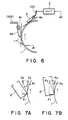
- Figures 9A, 9B and 9C show various examples of supports of the contact charging blade 2 (or the cleaning blade 6A) by supporting members 100.
- Figure 9A shows an example wherein the blade is sandwiched by supporting members 100;
- Figure 9B shows an example wherein the blade is bonded to the support;
- Figure 9C shows an example wherein the blade is integrally supported by molding or by metal member.
Applications Claiming Priority (4)
| Application Number | Priority Date | Filing Date | Title |
|---|---|---|---|
| JP25129687A JPH0193762A (ja) | 1987-10-05 | 1987-10-05 | 画像形成装置 |
| JP251296/87 | 1987-10-05 | ||
| JP25129587A JPH0193761A (ja) | 1987-10-05 | 1987-10-05 | 画像形成装置 |
| JP251295/87 | 1987-10-05 |
Publications (3)
| Publication Number | Publication Date |
|---|---|
| EP0312230A2 true EP0312230A2 (de) | 1989-04-19 |
| EP0312230A3 EP0312230A3 (en) | 1989-10-11 |
| EP0312230B1 EP0312230B1 (de) | 1994-05-25 |
Family
ID=26540141
Family Applications (1)
| Application Number | Title | Priority Date | Filing Date |
|---|---|---|---|
| EP19880309163 Expired - Lifetime EP0312230B1 (de) | 1987-10-05 | 1988-10-03 | Bilderzeugungsgerät |
Country Status (3)
| Country | Link |
|---|---|
| EP (1) | EP0312230B1 (de) |
| DE (1) | DE3889708T2 (de) |
| FR (1) | FR2621405B1 (de) |
Cited By (12)
| Publication number | Priority date | Publication date | Assignee | Title |
|---|---|---|---|---|
| EP0338546A2 (de) * | 1988-04-20 | 1989-10-25 | Canon Kabushiki Kaisha | Aufladevorrichtung und Bilderzeugungsgerät mit dieser |
| EP0431559A2 (de) * | 1989-12-04 | 1991-06-12 | Canon Kabushiki Kaisha | Bilderzeugungsgerät mit Auflademitteln |
| GB2239721A (en) * | 1989-12-05 | 1991-07-10 | Ricoh Kk | Improvements in, or relating to, image recording apparatus |
| EP0439145A2 (de) * | 1990-01-24 | 1991-07-31 | Canon Kabushiki Kaisha | Auflade-Element mit einer Elektrodenstruktur und dieses verwendende Aufladevorrichtung in einer abnehmbaren Arbeitseinheit für ein Bilderzeugungsgerät |
| EP0439143A2 (de) * | 1990-01-24 | 1991-07-31 | Canon Kabushiki Kaisha | Auflade-Element mit einer Schnittkante, und dieses Element verwendende Aufladevorrichtung in einer abnehmbaren Arbeitseinheit für ein Bilderzeugungsgerät |
| US5060014A (en) * | 1989-04-05 | 1991-10-22 | Canon Kabushiki Kaisha | Image forming apparatus and detachable process kit utilizing a drum charging means in relatively light contact pressure therewith |
| US5068762A (en) * | 1988-11-22 | 1991-11-26 | Canon Kabushiki Kaisha | Electrophotographic charging device |
| EP0515164A2 (de) * | 1991-05-20 | 1992-11-25 | Canon Kabushiki Kaisha | Aufladevorrichtung mit Aufladeblatt und damit versehenes Bilderzeugungsgerät und Arbeitseinheit |
| US5321472A (en) * | 1990-01-24 | 1994-06-14 | Canon Kabushiki Kaisha | Charging member with a bridging electrode structure and charging device using same in an image forming apparatus |
| US5357322A (en) * | 1990-01-24 | 1994-10-18 | Canon Kabushiki Kaisha | Charger |
| EP0629928A2 (de) * | 1993-05-31 | 1994-12-21 | Ricoh Company, Ltd | Rolle, Aufladegerät und Bilderzeugungsgerät unter Verwendung derselben |
| EP0691594A1 (de) * | 1994-07-06 | 1996-01-10 | Canon Kabushiki Kaisha | Elektrografisches Gerät und Bilderzeugungsverfahren |
Citations (6)
| Publication number | Priority date | Publication date | Assignee | Title |
|---|---|---|---|---|
| JPS5879277A (ja) * | 1981-11-06 | 1983-05-13 | Canon Inc | 電子写真法 |
| US4387980A (en) * | 1979-12-25 | 1983-06-14 | Tokyo Shibaura Denki Kabushiki Kaisha | Charging device for electronic copier |
| JPS60147756A (ja) * | 1984-01-13 | 1985-08-03 | Toshiba Corp | 帯電装置 |
| US4540268A (en) * | 1983-04-25 | 1985-09-10 | Canon Kabushiki Kaisha | Process kit and image forming apparatus using such kit |
| JPS61140972A (ja) * | 1984-12-12 | 1986-06-28 | Konishiroku Photo Ind Co Ltd | クリ−ニング装置 |
| JPS62175781A (ja) * | 1986-01-30 | 1987-08-01 | Mita Ind Co Ltd | 電子写真装置 |
-
1988
- 1988-10-03 EP EP19880309163 patent/EP0312230B1/de not_active Expired - Lifetime
- 1988-10-03 DE DE19883889708 patent/DE3889708T2/de not_active Expired - Lifetime
- 1988-10-05 FR FR8813029A patent/FR2621405B1/fr not_active Expired - Lifetime
Patent Citations (6)
| Publication number | Priority date | Publication date | Assignee | Title |
|---|---|---|---|---|
| US4387980A (en) * | 1979-12-25 | 1983-06-14 | Tokyo Shibaura Denki Kabushiki Kaisha | Charging device for electronic copier |
| JPS5879277A (ja) * | 1981-11-06 | 1983-05-13 | Canon Inc | 電子写真法 |
| US4540268A (en) * | 1983-04-25 | 1985-09-10 | Canon Kabushiki Kaisha | Process kit and image forming apparatus using such kit |
| JPS60147756A (ja) * | 1984-01-13 | 1985-08-03 | Toshiba Corp | 帯電装置 |
| JPS61140972A (ja) * | 1984-12-12 | 1986-06-28 | Konishiroku Photo Ind Co Ltd | クリ−ニング装置 |
| JPS62175781A (ja) * | 1986-01-30 | 1987-08-01 | Mita Ind Co Ltd | 電子写真装置 |
Non-Patent Citations (4)
| Title |
|---|
| PATENT ABSTRACTS OF JAPAN, vol. 10, no. 338 (P-516)(2394) 15 November 1986; & JP-A-61 140 972 (KONSHIROKU PHOTO IND) 28-06-1986 * |
| PATENT ABSTRACTS OF JAPAN, vol. 12, no. 19 (P-657)(2866) 21 January 1988; & JP-A-62 175 781 (MITA) 01-08-1987 * |
| PATENT ABSTRACTS OF JAPAN, vol. 7, no. 176 (P-214)(1321) 4 August 1983; & JP-A-58 079 277 (CANON) 13-05-1983 * |
| PATENT ABSTRACTS OF JAPAN, vol. 9, no. 320 (P-413)(2043) 14 December 1985; & JP-A-60 147 756 (TOSHIBA) 03-08-1985 * |
Cited By (24)
| Publication number | Priority date | Publication date | Assignee | Title |
|---|---|---|---|---|
| EP0338546A2 (de) * | 1988-04-20 | 1989-10-25 | Canon Kabushiki Kaisha | Aufladevorrichtung und Bilderzeugungsgerät mit dieser |
| EP0338546A3 (en) * | 1988-04-20 | 1990-08-08 | Canon Kabushiki Kaisha | Charger and image forming apparatus with same |
| US5420671A (en) * | 1988-04-20 | 1995-05-30 | Canon Kabushiki Kaisha | Charger and image forming apparatus with same |
| US5068762A (en) * | 1988-11-22 | 1991-11-26 | Canon Kabushiki Kaisha | Electrophotographic charging device |
| US5060014A (en) * | 1989-04-05 | 1991-10-22 | Canon Kabushiki Kaisha | Image forming apparatus and detachable process kit utilizing a drum charging means in relatively light contact pressure therewith |
| EP0431559A2 (de) * | 1989-12-04 | 1991-06-12 | Canon Kabushiki Kaisha | Bilderzeugungsgerät mit Auflademitteln |
| EP0431559A3 (en) * | 1989-12-04 | 1992-09-02 | Canon Kabushiki Kaisha | Image forming apparatus having charging means |
| GB2239721A (en) * | 1989-12-05 | 1991-07-10 | Ricoh Kk | Improvements in, or relating to, image recording apparatus |
| USRE35528E (en) * | 1989-12-05 | 1997-06-10 | Ricoh Company, Ltd. | Image recording apparatus having a toner supply tank and a toner recovery tank configured into a unitary, disposable magazine |
| US5126799A (en) * | 1989-12-05 | 1992-06-30 | Ricoh Company, Ltd. | Image recording apparatus having a toner supply tank and a toner recovery tank configured into a unitary, disposable magazine |
| GB2239721B (en) * | 1989-12-05 | 1994-04-27 | Ricoh Kk | Improvements in or relating to image recording apparatus |
| EP0439143A3 (en) * | 1990-01-24 | 1992-12-09 | Canon Kabushiki Kaisha | Charging member featureing a cut edge, and charging device employing same for use in a detachable process unit in an image forming apparatus |
| EP0439145A3 (en) * | 1990-01-24 | 1992-12-09 | Canon Kabushiki Kaisha | Charging member with a bridging electrode structure and charging device using same in a detachable process unit in an image forming apparatus |
| US5321472A (en) * | 1990-01-24 | 1994-06-14 | Canon Kabushiki Kaisha | Charging member with a bridging electrode structure and charging device using same in an image forming apparatus |
| US5353101A (en) * | 1990-01-24 | 1994-10-04 | Canon Kabushiki Kaisha | Charging member featuring a cut edge, and charging device employing same for use in a detachable process unit in an image forming apparatus |
| US5357322A (en) * | 1990-01-24 | 1994-10-18 | Canon Kabushiki Kaisha | Charger |
| EP0439143A2 (de) * | 1990-01-24 | 1991-07-31 | Canon Kabushiki Kaisha | Auflade-Element mit einer Schnittkante, und dieses Element verwendende Aufladevorrichtung in einer abnehmbaren Arbeitseinheit für ein Bilderzeugungsgerät |
| EP0439145A2 (de) * | 1990-01-24 | 1991-07-31 | Canon Kabushiki Kaisha | Auflade-Element mit einer Elektrodenstruktur und dieses verwendende Aufladevorrichtung in einer abnehmbaren Arbeitseinheit für ein Bilderzeugungsgerät |
| EP0515164A3 (en) * | 1991-05-20 | 1993-11-03 | Canon Kk | Charger having charging blade, image forming apparatus having same and process cartridge having same |
| EP0515164A2 (de) * | 1991-05-20 | 1992-11-25 | Canon Kabushiki Kaisha | Aufladevorrichtung mit Aufladeblatt und damit versehenes Bilderzeugungsgerät und Arbeitseinheit |
| EP0629928A2 (de) * | 1993-05-31 | 1994-12-21 | Ricoh Company, Ltd | Rolle, Aufladegerät und Bilderzeugungsgerät unter Verwendung derselben |
| EP0629928A3 (de) * | 1993-05-31 | 1998-07-29 | Ricoh Company, Ltd | Rolle, Aufladegerät und Bilderzeugungsgerät unter Verwendung derselben |
| EP0691594A1 (de) * | 1994-07-06 | 1996-01-10 | Canon Kabushiki Kaisha | Elektrografisches Gerät und Bilderzeugungsverfahren |
| US5667926A (en) * | 1994-07-06 | 1997-09-16 | Canon Kabushiki Kaisha | Electrophotographic apparatus and image forming process |
Also Published As
| Publication number | Publication date |
|---|---|
| DE3889708D1 (de) | 1994-06-30 |
| DE3889708T2 (de) | 1994-09-22 |
| FR2621405A1 (fr) | 1989-04-07 |
| FR2621405B1 (fr) | 1990-08-31 |
| EP0312230B1 (de) | 1994-05-25 |
| EP0312230A3 (en) | 1989-10-11 |
Similar Documents
| Publication | Publication Date | Title |
|---|---|---|
| US5168309A (en) | Image forming apparatus having a charging member and a cleaning member and a process cartridge detachably mountable to same | |
| EP0554114B1 (de) | Aufladungsteil, Aufladungsvorrichtung, Prozesskassette und Bilderzeugungsgerät | |
| EP0443800B1 (de) | Aufladeverfahren und Aufladevorrichtung | |
| EP0338546B1 (de) | Aufladevorrichtung und Bilderzeugungsgerät mit dieser | |
| US5790927A (en) | Charging member and process cartridge having same | |
| EP0312230B1 (de) | Bilderzeugungsgerät | |
| EP0622704A2 (de) | Aufladeelement, Aufladevorrichtung, Arbeitseinheit und Bilderzeugungsgerät | |
| EP0458273B1 (de) | Aufladevorrichtung, Bilderzeugungsgerät mit einer solchen Vorrichtung und von dem Bilderzeugungsgerät abnehmbare Arbeitseinheit | |
| US5060014A (en) | Image forming apparatus and detachable process kit utilizing a drum charging means in relatively light contact pressure therewith | |
| US5353101A (en) | Charging member featuring a cut edge, and charging device employing same for use in a detachable process unit in an image forming apparatus | |
| EP0574208B1 (de) | Aufladungsteil und Bilderzeugungsgerät mit einem Kontaktaufladungsteil | |
| JPS6249625B2 (de) | ||
| US8849160B2 (en) | Bias charge roller having a continuous raised pattern on the outer surface | |
| KR100307890B1 (ko) | 화상 형성 장치 | |
| US7493063B2 (en) | Image-forming device comprising a contact charging unit | |
| US6014529A (en) | Charging apparatus | |
| US5535088A (en) | Contacting charging device for electrostatic photoreceptor drum | |
| US20020041776A1 (en) | Process cartridge and image forming apparatus | |
| US5678141A (en) | Charging apparatus and process cartridge | |
| EP0496399A2 (de) | Aufladevorrichtung zum Aufladen eines sich in der Nähe befindendes Elementes und Bilderzeugungsgerät mit einer solchen Vorrichtung | |
| JP2002169358A (ja) | 接触帯電装置 | |
| EP1229400B1 (de) | Druckvorrichtung mit einer elastischen Aufladerolle | |
| JPH1165391A (ja) | 画像形成装置 | |
| EP0691593A2 (de) | Bilderzeugungsgerät | |
| JPH03100676A (ja) | 帯電装置 |
Legal Events
| Date | Code | Title | Description |
|---|---|---|---|
| PUAI | Public reference made under article 153(3) epc to a published international application that has entered the european phase |
Free format text: ORIGINAL CODE: 0009012 |
|
| AK | Designated contracting states |
Kind code of ref document: A2 Designated state(s): DE GB IT |
|
| PUAL | Search report despatched |
Free format text: ORIGINAL CODE: 0009013 |
|
| AK | Designated contracting states |
Kind code of ref document: A3 Designated state(s): DE GB IT |
|
| 17P | Request for examination filed |
Effective date: 19900228 |
|
| 17Q | First examination report despatched |
Effective date: 19920430 |
|
| ITTA | It: last paid annual fee | ||
| GRAA | (expected) grant |
Free format text: ORIGINAL CODE: 0009210 |
|
| AK | Designated contracting states |
Kind code of ref document: B1 Designated state(s): DE GB IT |
|
| REF | Corresponds to: |
Ref document number: 3889708 Country of ref document: DE Date of ref document: 19940630 |
|
| ITF | It: translation for a ep patent filed |
Owner name: SOCIETA' ITALIANA BREVETTI S.P.A. |
|
| PLBE | No opposition filed within time limit |
Free format text: ORIGINAL CODE: 0009261 |
|
| STAA | Information on the status of an ep patent application or granted ep patent |
Free format text: STATUS: NO OPPOSITION FILED WITHIN TIME LIMIT |
|
| 26N | No opposition filed | ||
| REG | Reference to a national code |
Ref country code: GB Ref legal event code: IF02 |
|
| PGFP | Annual fee paid to national office [announced via postgrant information from national office to epo] |
Ref country code: DE Payment date: 20071031 Year of fee payment: 20 |
|
| PGFP | Annual fee paid to national office [announced via postgrant information from national office to epo] |
Ref country code: IT Payment date: 20071019 Year of fee payment: 20 |
|
| PGFP | Annual fee paid to national office [announced via postgrant information from national office to epo] |
Ref country code: GB Payment date: 20071005 Year of fee payment: 20 |
|
| REG | Reference to a national code |
Ref country code: GB Ref legal event code: PE20 Expiry date: 20081002 |
|
| PG25 | Lapsed in a contracting state [announced via postgrant information from national office to epo] |
Ref country code: GB Free format text: LAPSE BECAUSE OF EXPIRATION OF PROTECTION Effective date: 20081002 |