EP0312010A2 - Dispositif émetteur et récepteur pour la transmission d'information par rayon lumineux - Google Patents
Dispositif émetteur et récepteur pour la transmission d'information par rayon lumineux Download PDFInfo
- Publication number
- EP0312010A2 EP0312010A2 EP88116932A EP88116932A EP0312010A2 EP 0312010 A2 EP0312010 A2 EP 0312010A2 EP 88116932 A EP88116932 A EP 88116932A EP 88116932 A EP88116932 A EP 88116932A EP 0312010 A2 EP0312010 A2 EP 0312010A2
- Authority
- EP
- European Patent Office
- Prior art keywords
- transmitting
- receiving
- receiving device
- diodes
- light
- Prior art date
- Legal status (The legal status is an assumption and is not a legal conclusion. Google has not performed a legal analysis and makes no representation as to the accuracy of the status listed.)
- Withdrawn
Links
Images

Classifications
-
- B—PERFORMING OPERATIONS; TRANSPORTING
- B60—VEHICLES IN GENERAL
- B60R—VEHICLES, VEHICLE FITTINGS, OR VEHICLE PARTS, NOT OTHERWISE PROVIDED FOR
- B60R1/00—Optical viewing arrangements; Real-time viewing arrangements for drivers or passengers using optical image capturing systems, e.g. cameras or video systems specially adapted for use in or on vehicles
- B60R1/12—Mirror assemblies combined with other articles, e.g. clocks
- B60R2001/1223—Mirror assemblies combined with other articles, e.g. clocks with sensors or transducers
-
- B—PERFORMING OPERATIONS; TRANSPORTING
- B60—VEHICLES IN GENERAL
- B60R—VEHICLES, VEHICLE FITTINGS, OR VEHICLE PARTS, NOT OTHERWISE PROVIDED FOR
- B60R1/00—Optical viewing arrangements; Real-time viewing arrangements for drivers or passengers using optical image capturing systems, e.g. cameras or video systems specially adapted for use in or on vehicles
- B60R1/12—Mirror assemblies combined with other articles, e.g. clocks
- B60R2001/1284—Mirror assemblies combined with other articles, e.g. clocks with communication systems other than radio-receivers, e.g. keyless entry systems, navigation systems; with anti-collision systems
-
- G—PHYSICS
- G08—SIGNALLING
- G08G—TRAFFIC CONTROL SYSTEMS
- G08G1/00—Traffic control systems for road vehicles
- G08G1/09—Arrangements for giving variable traffic instructions
- G08G1/0962—Arrangements for giving variable traffic instructions having an indicator mounted inside the vehicle, e.g. giving voice messages
- G08G1/0967—Systems involving transmission of highway information, e.g. weather, speed limits
- G08G1/096766—Systems involving transmission of highway information, e.g. weather, speed limits where the system is characterised by the origin of the information transmission
- G08G1/096783—Systems involving transmission of highway information, e.g. weather, speed limits where the system is characterised by the origin of the information transmission where the origin of the information is a roadside individual element
-
- G—PHYSICS
- G08—SIGNALLING
- G08G—TRAFFIC CONTROL SYSTEMS
- G08G1/00—Traffic control systems for road vehicles
- G08G1/09—Arrangements for giving variable traffic instructions
- G08G1/0962—Arrangements for giving variable traffic instructions having an indicator mounted inside the vehicle, e.g. giving voice messages
- G08G1/0967—Systems involving transmission of highway information, e.g. weather, speed limits
- G08G1/096766—Systems involving transmission of highway information, e.g. weather, speed limits where the system is characterised by the origin of the information transmission
- G08G1/096791—Systems involving transmission of highway information, e.g. weather, speed limits where the system is characterised by the origin of the information transmission where the origin of the information is another vehicle
Definitions
- the invention relates to a transmitting and receiving device according to the preamble of claim 1.
- DE-OS 36 05 681 describes such a device for transmitting information by means of infrared radiation.
- the information data are transmitted by means of light, preferably infrared radiation.
- Such an information and control system is described for example in DE-PS 29 23 634 or in DE-OS 32 48 544.
- the fixed beacons are arranged in the immediate vicinity of the usual traffic light signals. This means that the transmitting and receiving device in the vehicle must have the same visual contact with the beacon as the vehicle driver has with the light signal.
- This visual contact to the beacon for infrared transmission can be optimally established if the translucent cover plate of the transmitting and receiving device is aligned with the beacons. It is important that no extraneous light, especially sun rays, influences the transmission path and causes unpleasant disturbances. It was therefore proposed in DE-OS 36 05 681 to provide horizontal diaphragms with absorption surfaces against obliquely incident radiation from above in a light entry shaft in order to achieve low-loss optical shielding of the receiving diodes against interference from the sun. Furthermore, in the known transmission and reception device inside the housing, the transmission diodes are in a less deep area arranged in at least two rows one above the other behind the front wall without any intermediate or other optical lenses.
- the aim is to achieve the best possible reduction in interference from incident sunlight.
- the integration of the cover plate with the receiver lens and the transmission lenses as a one-piece part has the advantage that it can be manufactured as a molded part. Another advantage is that unnecessary optical surface losses at the respective interfaces are avoided because the translucent cover plate and the molded on it Lens is in one piece, so that there are a maximum of two interfaces to be penetrated in contrast to four interfaces so far. Furthermore, a deviation in centricity is avoided by the mechanical construction tolerances of the lens attachments with the cover disk designed according to the invention. In addition, this avoids additional deviations between the transmitting and receiving lenses in the assignment to the receiving and transmitting diodes, in particular if at least two spacers are formed on the inside either on the cover plate or on the housing for receiving the assembly circuit board.
- the design of the light inlet shaft according to the invention reduces the interference from incident sunlight, which is explained in more detail with reference to the subclaims.
- the transmitting and receiving device is arranged in the vehicle, for example behind the windscreen.
- the cover plate is flat on the outside and the inside is lenticular. This has the advantage that the front wall of the transmitting and receiving device can be easily cleaned.
- the receiving diodes, the light entry shaft and the associated receiving lens can be next to, i.e. be arranged to the left and / or right of or above or below the transmitter diodes or lenses.
- the cover disk is expediently designed as a spherical lens in the region of the receiving diodes and as horizontally extending cylindrical lenses arranged one above the other in the region of the transmission diodes.
- a sharp optical so-called tear-off edge is obtained, which contributes to the reduction of the interference from extraneous light, for example solar radiation from above.
- the light coming from the beacon is not imaged on the receiver diode as a sharp focal point or focal line, but rather as an active focal surface or focal land.
- each transmitter diode row that runs horizontally is assigned a cylindrical lens. It may be expedient to additionally form an additional cylindrical lens on the number of required cylindrical lenses at the upper and lower edge of the cover plate. This increases the stability of the cover plate and represents a clean solution in terms of production technology.
- Forming the inlet shaft of shield plates and providing a light-absorbing coating on the inside of the lower shield plate, and forming the other inner surfaces of the shield plates with a light-reflecting layer has the advantage that there is no reflection of obliquely incident external light from the lower shaft bottom, and that the incident useful light is reflected on the other surfaces onto the receiving diodes.
- the reflection on the conically relevant shielding plates it is achieved that the flat incident infrared light, which does not directly hit the receiving diodes, is reflected by the vertical shielding plates and by the upper shielding plate and additionally reaches the receiving diodes.
- sunlight falling at an angle from above is optically blocked by multiple reflections or interrupted by the absorption surface on the lower shield plate.
- an infrared scattered light is braked through the absorption surface.
- the inventive design of the light entry shaft therefore achieves a larger adaptation angle, because the adaptability of the receiving diodes over large angles of incidence enables the separating line of the cylindrical lens to be used directly via reflections on the conical ones Shaft walls forming shield plates above and below.
- the absence of the horizontal diaphragms in the irradiation area advantageously causes no transmission losses.
- the absorbent covering can expediently be formed from black velvet, because it represents the best possible optical absorption surface as the absorption material.
- the reflective inner sides are clad, so that the highly reflective shielding sheets for the reflection have a high optical efficiency. This has the advantage that there are no unnecessary transmission losses of the active transmitter radiation hitting the reflective shield plates laterally.
- This inventive design of the light entry shaft prevents direct sunlight and thus undesirable interference, so that a high degree of selectivity is achieved with a sharply defined adaptation angle.
- the near area of the receiving diodes is not provided with a light-absorbing coating on the lower shield plate. This ensures that infrared light incident flat from above is still reflected to the area of the receiving diode immediately in front of it.
- the upper and lower shield plates have molded-on locking lugs which are arranged in the front region and in the rear region and can be latched into corresponding, longitudinally extending recesses in the vertical shield plates.
- the resilient latching of the upper and lower shielding plates in the vertical shielding plates allows the funnel-shaped light entry shaft to be installed quickly and easily. It is advantageous that at least the upper shield plate in the rear area on one side has a longer locking lug compared to the other lugs and the vertical shield plate has a corresponding longitudinal recess. That has the advantage that a confusion of sides of the plated shield plate can be excluded during assembly.
- the respective vertical shield plate has a plurality of recesses in the front area, so that the upper and the lower shield plate can be locked in different recess pairs.
- This has the advantage that the radial adjustability of these reflecting surfaces can be changed and, as a result, different vertical adaptation angles of the receiver can be achieved.
- At least one recess is expediently provided on each vertical shield plate, which does not run in the alignment of the other, longitudinally extending recesses. This has the advantage that this non-positive connection of the upper and lower shield plates with the vertical shield plates results in a stable latching and rattling of the shield plates can be excluded in mobile operation.
- the transmitting and receiving device in the housing is generally from the inside adjustable exterior mirror installed.
- Such mirrors which are becoming increasingly popular, have a fixed housing. Only the mirror itself is adjusted within the housing. If the infrared transmitter / receiver is firmly connected to the housing, it maintains its orientation. Only when the mirror is folded down in the event of a shock that is provided for safety reasons is the alignment no longer given. However, this is not annoying, because the driver is not allowed to drive anyway when folded. The sudden folding does not adversely affect the transmitting and receiving device. When folding back, the outside mirror and thus the transmitting and receiving device return to their original position.
- the transmitting and receiving device is arranged in the right and in the left wing mirror.
- the security for data exchange is significantly increased by the double arrangement, because the fixed beacons are generally arranged to the left and right of the road in an advantageous manner directly on the signal mast of the traffic signal system. This also ensures transmission if, for example, the right wing mirror is in visual contact with the beacon, e.g. is shielded by a truck, or if the reception of a transmitting and receiving device is impaired by solar radiation.
- a related information transmission system is described in DE-OS 32 48 544.
- the fixed housing of the exterior mirror can be formed from an infrared-transparent material with the integrated transmission and reception optics, the transmission and reception diodes with the printed circuit board assembly being able to be arranged directly behind the lens unit.
- the spacers or supports for receiving the printed circuit board assembly can also be formed on the inside of the housing.
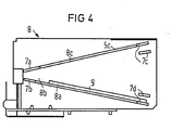
- the transmitting and receiving device is seen from above, partially shown in a tear.
- the receiving part is arranged in the left-hand region, which extends further to the rear, and in the less deep region, the transmitting diodes 2 are arranged on the right.
- the cover plate 4 is located in front of it.
- the light entry shaft designed according to the invention is arranged in the reception area, and the reception diodes 3 are arranged in its rear area, that is to say in the area of the rear of the device.
- the lens required at least in the reception area is omitted here.
- the cover plate 4 is shown.
- the cover plate is seen from behind in FIG. 2, so that the receiving optics 6 can be clearly seen in the left area.
- This is designed as a spherical lens and is formed in one piece with the cover plate 4.
- This can be seen very clearly in the side view of the cover plate 4 in FIG.
- 6 horizontally extending, cylindrical lenses 5, which are arranged one above the other, are integrated in the cover plate 4 in the area of the transmitter diodes.
- the cylindrical lenses 5 cause a wide radiation in the horizontal angle, in contrast, in the vertical angle, a very narrow radiation, which for example can have a half-value angle of approximately 3 ° each upwards and downwards. Without these cylindrical lenses, common diodes have a half-value angle of 11 ° each.
- the configuration according to the invention achieves a substantially better yield of the transmission energy.
- the receiving diodes 3 are arranged at the funnel end.
- the vertical shield plates 7 have longitudinal recesses 7a to 7c, in which the upper 8c and the lower 8a shield plate can be locked with respective lugs.
- the light-absorbing covering 9 which can be made of black velvet, for example, extend to the funnel opening. Further details can be seen in the sectional drawing in FIG. 5.
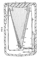
- the funnel-shaped light entry shaft 8, which has the receiving diodes 3 at its funnel end, is arranged inside the housing 1 in section.
- the cover plate 4 has an integrated spherical lens 6, which faces the interior of the shaft.
- the shaft is formed by two vertical shield plates 7 and an upper shield plate 8c and a lower shield plate 8a.
- the upper and the lower shield plate are locked with respective locking lugs.
- One recess 7a and the corresponding locking lug are longer than the others, so that the upper shield plate 8c, which is clad on the inside to achieve high reflection, cannot be confused during installation, ie installed with the reflecting side facing upwards can be.
- This longer recess 7a is made, for example, in the left vertical shield plate.
- the recess 7b does not run in the line of alignment of the other recesses, so that a non-positive connection is produced when the latching lug is locked.
- an additional pair of recesses 7c and 7b is shown, into which the upper and lower shield plates can be snapped in if the opening angle is to be smaller than shown here.
- the inside of the lower shield plate 8a has a non-absorbent covering 9, which, however, does not extend directly to the receiving diodes 3.
- the close range 8b can also have a reflective layer, so that flatly incident infrared radiation in this close range still reaches the reception diodes 3 are reflected.
- Fig. 5 a series of incident light rays are drawn in, which either arrive directly at the receiving diodes 3 or via reflection on the upper shield plate 8c to the receiving diodes 3.
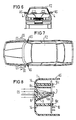
- Fig. 6 shows a vehicle FZ in front view with side mirrors AS, in which the transmitting and receiving device is installed and has a translucent windshield 4 in the direction of travel.
- FIG. 7 shows a plan view of a vehicle FZ with the transmitting and receiving devices arranged on the left and right side mirrors AS.
- the infrared transmission and reception radiation SS and ES are indicated.
- the housing 1 of an outside mirror AS is shown schematically in section, but without the actual mirror. Only a basic illustration is shown here, which is intended to show the essential elements according to the invention.
- the housing 1 of the outside mirror AS with the integrated receiving and transmitting lenses will be adapted to the vehicle-specific mirror model.
- the wall of the housing 1 is formed from an infrared-transparent material to form a transmitting and receiving lens. Only the receiving lens 6 is shown here. It focuses the infrared radiation ES on the receiving diodes 3, only one shown here.
- the receiving diodes 3 and the transmission diodes (2), not shown here, are arranged on a printed circuit board assembly 10 which is screwed onto corresponding supports 14 (10c).
- the supports or the spacers 14 can be integrally formed on the housing 1.
- webs or walls 8c and 8a formed on the housing 1 can also be formed as "shielding plates” and form a non-entry shaft 8 for the receiving diodes 3.
- these molded webs 8c and 8a are not designed to be transparent to infrared light.
- the lower web 8a can be coated with a light-absorbing material 9.
Applications Claiming Priority (6)
| Application Number | Priority Date | Filing Date | Title |
|---|---|---|---|
| DE8713877U DE8713877U1 (fr) | 1987-10-15 | 1987-10-15 | |
| DE8713877U | 1987-10-15 | ||
| DE8713878U | 1987-10-15 | ||
| DE8713878U DE8713878U1 (fr) | 1987-10-15 | 1987-10-15 | |
| DE8804737U DE8804737U1 (fr) | 1988-04-11 | 1988-04-11 | |
| DE8804737U | 1988-04-11 |
Publications (2)
| Publication Number | Publication Date |
|---|---|
| EP0312010A2 true EP0312010A2 (fr) | 1989-04-19 |
| EP0312010A3 EP0312010A3 (fr) | 1989-08-02 |
Family
ID=27207803
Family Applications (1)
| Application Number | Title | Priority Date | Filing Date |
|---|---|---|---|
| EP88116932A Withdrawn EP0312010A3 (fr) | 1987-10-15 | 1988-10-12 | Dispositif émetteur et récepteur pour la transmission d'information par rayon lumineux |
Country Status (1)
| Country | Link |
|---|---|
| EP (1) | EP0312010A3 (fr) |
Cited By (4)
| Publication number | Priority date | Publication date | Assignee | Title |
|---|---|---|---|---|
| US5383500A (en) * | 1992-03-19 | 1995-01-24 | Shell Oil Company | Automatic refuelling system |
| EP0814343A2 (fr) * | 1996-06-17 | 1997-12-29 | Harness System Technologies Research, Ltd. | Tête optique pour balise optique |
| DE19801884A1 (de) * | 1998-01-20 | 1999-07-22 | Mannesmann Vdo Ag | Überwachungssystem für Fahrzeuge |
| US6596713B1 (en) | 1994-09-14 | 2003-07-22 | Schering Aktiengesellschaft | Steroid esters and amides, process for their production and their pharmaceutical use |
Citations (3)
| Publication number | Priority date | Publication date | Assignee | Title |
|---|---|---|---|---|
| FR2468172A1 (fr) * | 1979-10-23 | 1981-04-30 | Robert Philippe | Procede de controle des possibilites de changement de direction sans risque des vehicules et moyen de mise en oeuvre |
| DE3248544A1 (de) * | 1982-12-29 | 1984-07-12 | Siemens AG, 1000 Berlin und 8000 München | System zur informationsuebertragung mittels infrarotstrahlung |
| EP0235678A1 (fr) * | 1986-02-21 | 1987-09-09 | Siemens Aktiengesellschaft | Dispositif transmetteur et récepteur pour installation dans un véhicule |
-
1988
- 1988-10-12 EP EP88116932A patent/EP0312010A3/fr not_active Withdrawn
Patent Citations (3)
| Publication number | Priority date | Publication date | Assignee | Title |
|---|---|---|---|---|
| FR2468172A1 (fr) * | 1979-10-23 | 1981-04-30 | Robert Philippe | Procede de controle des possibilites de changement de direction sans risque des vehicules et moyen de mise en oeuvre |
| DE3248544A1 (de) * | 1982-12-29 | 1984-07-12 | Siemens AG, 1000 Berlin und 8000 München | System zur informationsuebertragung mittels infrarotstrahlung |
| EP0235678A1 (fr) * | 1986-02-21 | 1987-09-09 | Siemens Aktiengesellschaft | Dispositif transmetteur et récepteur pour installation dans un véhicule |
Cited By (6)
| Publication number | Priority date | Publication date | Assignee | Title |
|---|---|---|---|---|
| US5383500A (en) * | 1992-03-19 | 1995-01-24 | Shell Oil Company | Automatic refuelling system |
| US6596713B1 (en) | 1994-09-14 | 2003-07-22 | Schering Aktiengesellschaft | Steroid esters and amides, process for their production and their pharmaceutical use |
| EP0814343A2 (fr) * | 1996-06-17 | 1997-12-29 | Harness System Technologies Research, Ltd. | Tête optique pour balise optique |
| EP0814343A3 (fr) * | 1996-06-17 | 1998-08-05 | Harness System Technologies Research, Ltd. | Tête optique pour balise optique |
| US5999296A (en) * | 1996-06-17 | 1999-12-07 | Harness System Technologies Research Ltd. | Optical head of optical beacon |
| DE19801884A1 (de) * | 1998-01-20 | 1999-07-22 | Mannesmann Vdo Ag | Überwachungssystem für Fahrzeuge |
Also Published As
| Publication number | Publication date |
|---|---|
| EP0312010A3 (fr) | 1989-08-02 |
Similar Documents
| Publication | Publication Date | Title |
|---|---|---|
| DE69918048T2 (de) | Tor für Kraftfahrzeug mit System zur Objekterfassung | |
| DE2648604C3 (de) | Linse für einen Lichtsender in einem Fernsteuersystem | |
| DE60127130T2 (de) | Optischer regensensor | |
| DE102017203793B4 (de) | Fahrzeug | |
| DE102013012789A1 (de) | Abtastende optoelektronische Detektionseinrichtung und Kraftfahrzeug mit einer solchen Detektionseinrichtung | |
| EP2786168A1 (fr) | Dispositif de mesure optique | |
| DE102012212150B4 (de) | Laserradarvorrichtung, die zwischen einem Kennzeichenschild und einemFahrzeugaufbau angeordnet ist | |
| EP2112039A2 (fr) | Dispositif de capteur optique | |
| EP1836462B1 (fr) | Dispositif capteur, notamment pour un vehicule automobile | |
| DE4104233A1 (de) | Kraftfahrzeug-anzeigevorrichtung vom reflexionstyp | |
| EP0843180A1 (fr) | Télémétrie | |
| EP0897121A2 (fr) | Dispositif pour localiser l'entrée d'objets dans un domaine spatial surveillé | |
| DE112019000621T5 (de) | Lidar-vorrichtung | |
| EP2176098A1 (fr) | Dispositif pour déterminer les propriétés réflectives d'une surface limite | |
| DE102019218005A1 (de) | LIDAR-Sensor | |
| EP2833161A1 (fr) | Dispositif de mesure optoélectronique pour un véhicule automobile et capteur à balayage associé | |
| WO2013013872A1 (fr) | Dispositif de mesure optique pour un véhicule | |
| EP0330165B1 (fr) | Dispositif d'émission et de réception pour la transmission d'informations dans la bande infrarouge | |
| EP0312010A2 (fr) | Dispositif émetteur et récepteur pour la transmission d'information par rayon lumineux | |
| DE10214572A1 (de) | Niederschlags-Sensor | |
| EP2185917B1 (fr) | Dispositif optique de detection de pluie pour vehicule automobile | |
| EP0235678A1 (fr) | Dispositif transmetteur et récepteur pour installation dans un véhicule | |
| DE102016117853A1 (de) | Sendeeinrichtung für eine optische Erfassungsvorrichtung, optische Erfassungsvorrichtung, Kraftfahrzeug sowie Verfahren | |
| DE102019106544B4 (de) | Messvorrichtung zur Erfassung des Umgebungslichts, Regen-Licht-Sensor zur Verwendung an einer Windschutzscheibe und Kraftfahrzeug | |
| DE4222659A1 (de) | Abtastender Scanner für Entfernungsmesser |
Legal Events
| Date | Code | Title | Description |
|---|---|---|---|
| PUAI | Public reference made under article 153(3) epc to a published international application that has entered the european phase |
Free format text: ORIGINAL CODE: 0009012 |
|
| AK | Designated contracting states |
Kind code of ref document: A2 Designated state(s): DE ES FR GB IT NL |
|
| PUAL | Search report despatched |
Free format text: ORIGINAL CODE: 0009013 |
|
| AK | Designated contracting states |
Kind code of ref document: A3 Designated state(s): DE ES FR GB IT NL |
|
| 17P | Request for examination filed |
Effective date: 19900129 |
|
| 17Q | First examination report despatched |
Effective date: 19921005 |
|
| STAA | Information on the status of an ep patent application or granted ep patent |
Free format text: STATUS: THE APPLICATION IS DEEMED TO BE WITHDRAWN |
|
| 18D | Application deemed to be withdrawn |
Effective date: 19930713 |