EP0312010A2 - Transmitter and receiver device for the transmission of information by light beams - Google Patents
Transmitter and receiver device for the transmission of information by light beams Download PDFInfo
- Publication number
- EP0312010A2 EP0312010A2 EP88116932A EP88116932A EP0312010A2 EP 0312010 A2 EP0312010 A2 EP 0312010A2 EP 88116932 A EP88116932 A EP 88116932A EP 88116932 A EP88116932 A EP 88116932A EP 0312010 A2 EP0312010 A2 EP 0312010A2
- Authority
- EP
- European Patent Office
- Prior art keywords
- transmitting
- receiving
- receiving device
- diodes
- light
- Prior art date
- Legal status (The legal status is an assumption and is not a legal conclusion. Google has not performed a legal analysis and makes no representation as to the accuracy of the status listed.)
- Withdrawn
Links
Images

Classifications
-
- B—PERFORMING OPERATIONS; TRANSPORTING
- B60—VEHICLES IN GENERAL
- B60R—VEHICLES, VEHICLE FITTINGS, OR VEHICLE PARTS, NOT OTHERWISE PROVIDED FOR
- B60R1/00—Optical viewing arrangements; Real-time viewing arrangements for drivers or passengers using optical image capturing systems, e.g. cameras or video systems specially adapted for use in or on vehicles
- B60R1/12—Mirror assemblies combined with other articles, e.g. clocks
- B60R2001/1223—Mirror assemblies combined with other articles, e.g. clocks with sensors or transducers
-
- B—PERFORMING OPERATIONS; TRANSPORTING
- B60—VEHICLES IN GENERAL
- B60R—VEHICLES, VEHICLE FITTINGS, OR VEHICLE PARTS, NOT OTHERWISE PROVIDED FOR
- B60R1/00—Optical viewing arrangements; Real-time viewing arrangements for drivers or passengers using optical image capturing systems, e.g. cameras or video systems specially adapted for use in or on vehicles
- B60R1/12—Mirror assemblies combined with other articles, e.g. clocks
- B60R2001/1284—Mirror assemblies combined with other articles, e.g. clocks with communication systems other than radio-receivers, e.g. keyless entry systems, navigation systems; with anti-collision systems
-
- G—PHYSICS
- G08—SIGNALLING
- G08G—TRAFFIC CONTROL SYSTEMS
- G08G1/00—Traffic control systems for road vehicles
- G08G1/09—Arrangements for giving variable traffic instructions
- G08G1/0962—Arrangements for giving variable traffic instructions having an indicator mounted inside the vehicle, e.g. giving voice messages
- G08G1/0967—Systems involving transmission of highway information, e.g. weather, speed limits
- G08G1/096766—Systems involving transmission of highway information, e.g. weather, speed limits where the system is characterised by the origin of the information transmission
- G08G1/096783—Systems involving transmission of highway information, e.g. weather, speed limits where the system is characterised by the origin of the information transmission where the origin of the information is a roadside individual element
-
- G—PHYSICS
- G08—SIGNALLING
- G08G—TRAFFIC CONTROL SYSTEMS
- G08G1/00—Traffic control systems for road vehicles
- G08G1/09—Arrangements for giving variable traffic instructions
- G08G1/0962—Arrangements for giving variable traffic instructions having an indicator mounted inside the vehicle, e.g. giving voice messages
- G08G1/0967—Systems involving transmission of highway information, e.g. weather, speed limits
- G08G1/096766—Systems involving transmission of highway information, e.g. weather, speed limits where the system is characterised by the origin of the information transmission
- G08G1/096791—Systems involving transmission of highway information, e.g. weather, speed limits where the system is characterised by the origin of the information transmission where the origin of the information is another vehicle
Definitions
- the invention relates to a transmitting and receiving device according to the preamble of claim 1.
- DE-OS 36 05 681 describes such a device for transmitting information by means of infrared radiation.
- the information data are transmitted by means of light, preferably infrared radiation.
- Such an information and control system is described for example in DE-PS 29 23 634 or in DE-OS 32 48 544.
- the fixed beacons are arranged in the immediate vicinity of the usual traffic light signals. This means that the transmitting and receiving device in the vehicle must have the same visual contact with the beacon as the vehicle driver has with the light signal.
- This visual contact to the beacon for infrared transmission can be optimally established if the translucent cover plate of the transmitting and receiving device is aligned with the beacons. It is important that no extraneous light, especially sun rays, influences the transmission path and causes unpleasant disturbances. It was therefore proposed in DE-OS 36 05 681 to provide horizontal diaphragms with absorption surfaces against obliquely incident radiation from above in a light entry shaft in order to achieve low-loss optical shielding of the receiving diodes against interference from the sun. Furthermore, in the known transmission and reception device inside the housing, the transmission diodes are in a less deep area arranged in at least two rows one above the other behind the front wall without any intermediate or other optical lenses.
- the aim is to achieve the best possible reduction in interference from incident sunlight.
- the integration of the cover plate with the receiver lens and the transmission lenses as a one-piece part has the advantage that it can be manufactured as a molded part. Another advantage is that unnecessary optical surface losses at the respective interfaces are avoided because the translucent cover plate and the molded on it Lens is in one piece, so that there are a maximum of two interfaces to be penetrated in contrast to four interfaces so far. Furthermore, a deviation in centricity is avoided by the mechanical construction tolerances of the lens attachments with the cover disk designed according to the invention. In addition, this avoids additional deviations between the transmitting and receiving lenses in the assignment to the receiving and transmitting diodes, in particular if at least two spacers are formed on the inside either on the cover plate or on the housing for receiving the assembly circuit board.
- the design of the light inlet shaft according to the invention reduces the interference from incident sunlight, which is explained in more detail with reference to the subclaims.
- the transmitting and receiving device is arranged in the vehicle, for example behind the windscreen.
- the cover plate is flat on the outside and the inside is lenticular. This has the advantage that the front wall of the transmitting and receiving device can be easily cleaned.
- the receiving diodes, the light entry shaft and the associated receiving lens can be next to, i.e. be arranged to the left and / or right of or above or below the transmitter diodes or lenses.
- the cover disk is expediently designed as a spherical lens in the region of the receiving diodes and as horizontally extending cylindrical lenses arranged one above the other in the region of the transmission diodes.
- a sharp optical so-called tear-off edge is obtained, which contributes to the reduction of the interference from extraneous light, for example solar radiation from above.
- the light coming from the beacon is not imaged on the receiver diode as a sharp focal point or focal line, but rather as an active focal surface or focal land.
- each transmitter diode row that runs horizontally is assigned a cylindrical lens. It may be expedient to additionally form an additional cylindrical lens on the number of required cylindrical lenses at the upper and lower edge of the cover plate. This increases the stability of the cover plate and represents a clean solution in terms of production technology.
- Forming the inlet shaft of shield plates and providing a light-absorbing coating on the inside of the lower shield plate, and forming the other inner surfaces of the shield plates with a light-reflecting layer has the advantage that there is no reflection of obliquely incident external light from the lower shaft bottom, and that the incident useful light is reflected on the other surfaces onto the receiving diodes.
- the reflection on the conically relevant shielding plates it is achieved that the flat incident infrared light, which does not directly hit the receiving diodes, is reflected by the vertical shielding plates and by the upper shielding plate and additionally reaches the receiving diodes.
- sunlight falling at an angle from above is optically blocked by multiple reflections or interrupted by the absorption surface on the lower shield plate.
- an infrared scattered light is braked through the absorption surface.
- the inventive design of the light entry shaft therefore achieves a larger adaptation angle, because the adaptability of the receiving diodes over large angles of incidence enables the separating line of the cylindrical lens to be used directly via reflections on the conical ones Shaft walls forming shield plates above and below.
- the absence of the horizontal diaphragms in the irradiation area advantageously causes no transmission losses.
- the absorbent covering can expediently be formed from black velvet, because it represents the best possible optical absorption surface as the absorption material.
- the reflective inner sides are clad, so that the highly reflective shielding sheets for the reflection have a high optical efficiency. This has the advantage that there are no unnecessary transmission losses of the active transmitter radiation hitting the reflective shield plates laterally.
- This inventive design of the light entry shaft prevents direct sunlight and thus undesirable interference, so that a high degree of selectivity is achieved with a sharply defined adaptation angle.
- the near area of the receiving diodes is not provided with a light-absorbing coating on the lower shield plate. This ensures that infrared light incident flat from above is still reflected to the area of the receiving diode immediately in front of it.
- the upper and lower shield plates have molded-on locking lugs which are arranged in the front region and in the rear region and can be latched into corresponding, longitudinally extending recesses in the vertical shield plates.
- the resilient latching of the upper and lower shielding plates in the vertical shielding plates allows the funnel-shaped light entry shaft to be installed quickly and easily. It is advantageous that at least the upper shield plate in the rear area on one side has a longer locking lug compared to the other lugs and the vertical shield plate has a corresponding longitudinal recess. That has the advantage that a confusion of sides of the plated shield plate can be excluded during assembly.
- the respective vertical shield plate has a plurality of recesses in the front area, so that the upper and the lower shield plate can be locked in different recess pairs.
- This has the advantage that the radial adjustability of these reflecting surfaces can be changed and, as a result, different vertical adaptation angles of the receiver can be achieved.
- At least one recess is expediently provided on each vertical shield plate, which does not run in the alignment of the other, longitudinally extending recesses. This has the advantage that this non-positive connection of the upper and lower shield plates with the vertical shield plates results in a stable latching and rattling of the shield plates can be excluded in mobile operation.
- the transmitting and receiving device in the housing is generally from the inside adjustable exterior mirror installed.
- Such mirrors which are becoming increasingly popular, have a fixed housing. Only the mirror itself is adjusted within the housing. If the infrared transmitter / receiver is firmly connected to the housing, it maintains its orientation. Only when the mirror is folded down in the event of a shock that is provided for safety reasons is the alignment no longer given. However, this is not annoying, because the driver is not allowed to drive anyway when folded. The sudden folding does not adversely affect the transmitting and receiving device. When folding back, the outside mirror and thus the transmitting and receiving device return to their original position.
- the transmitting and receiving device is arranged in the right and in the left wing mirror.
- the security for data exchange is significantly increased by the double arrangement, because the fixed beacons are generally arranged to the left and right of the road in an advantageous manner directly on the signal mast of the traffic signal system. This also ensures transmission if, for example, the right wing mirror is in visual contact with the beacon, e.g. is shielded by a truck, or if the reception of a transmitting and receiving device is impaired by solar radiation.
- a related information transmission system is described in DE-OS 32 48 544.
- the fixed housing of the exterior mirror can be formed from an infrared-transparent material with the integrated transmission and reception optics, the transmission and reception diodes with the printed circuit board assembly being able to be arranged directly behind the lens unit.
- the spacers or supports for receiving the printed circuit board assembly can also be formed on the inside of the housing.
- the transmitting and receiving device is seen from above, partially shown in a tear.
- the receiving part is arranged in the left-hand region, which extends further to the rear, and in the less deep region, the transmitting diodes 2 are arranged on the right.
- the cover plate 4 is located in front of it.
- the light entry shaft designed according to the invention is arranged in the reception area, and the reception diodes 3 are arranged in its rear area, that is to say in the area of the rear of the device.
- the lens required at least in the reception area is omitted here.
- the cover plate 4 is shown.
- the cover plate is seen from behind in FIG. 2, so that the receiving optics 6 can be clearly seen in the left area.
- This is designed as a spherical lens and is formed in one piece with the cover plate 4.
- This can be seen very clearly in the side view of the cover plate 4 in FIG.
- 6 horizontally extending, cylindrical lenses 5, which are arranged one above the other, are integrated in the cover plate 4 in the area of the transmitter diodes.
- the cylindrical lenses 5 cause a wide radiation in the horizontal angle, in contrast, in the vertical angle, a very narrow radiation, which for example can have a half-value angle of approximately 3 ° each upwards and downwards. Without these cylindrical lenses, common diodes have a half-value angle of 11 ° each.
- the configuration according to the invention achieves a substantially better yield of the transmission energy.
- the receiving diodes 3 are arranged at the funnel end.
- the vertical shield plates 7 have longitudinal recesses 7a to 7c, in which the upper 8c and the lower 8a shield plate can be locked with respective lugs.
- the light-absorbing covering 9 which can be made of black velvet, for example, extend to the funnel opening. Further details can be seen in the sectional drawing in FIG. 5.
- the funnel-shaped light entry shaft 8, which has the receiving diodes 3 at its funnel end, is arranged inside the housing 1 in section.
- the cover plate 4 has an integrated spherical lens 6, which faces the interior of the shaft.
- the shaft is formed by two vertical shield plates 7 and an upper shield plate 8c and a lower shield plate 8a.
- the upper and the lower shield plate are locked with respective locking lugs.
- One recess 7a and the corresponding locking lug are longer than the others, so that the upper shield plate 8c, which is clad on the inside to achieve high reflection, cannot be confused during installation, ie installed with the reflecting side facing upwards can be.
- This longer recess 7a is made, for example, in the left vertical shield plate.
- the recess 7b does not run in the line of alignment of the other recesses, so that a non-positive connection is produced when the latching lug is locked.
- an additional pair of recesses 7c and 7b is shown, into which the upper and lower shield plates can be snapped in if the opening angle is to be smaller than shown here.
- the inside of the lower shield plate 8a has a non-absorbent covering 9, which, however, does not extend directly to the receiving diodes 3.
- the close range 8b can also have a reflective layer, so that flatly incident infrared radiation in this close range still reaches the reception diodes 3 are reflected.
- Fig. 5 a series of incident light rays are drawn in, which either arrive directly at the receiving diodes 3 or via reflection on the upper shield plate 8c to the receiving diodes 3.
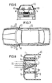
- Fig. 6 shows a vehicle FZ in front view with side mirrors AS, in which the transmitting and receiving device is installed and has a translucent windshield 4 in the direction of travel.
- FIG. 7 shows a plan view of a vehicle FZ with the transmitting and receiving devices arranged on the left and right side mirrors AS.
- the infrared transmission and reception radiation SS and ES are indicated.
- the housing 1 of an outside mirror AS is shown schematically in section, but without the actual mirror. Only a basic illustration is shown here, which is intended to show the essential elements according to the invention.
- the housing 1 of the outside mirror AS with the integrated receiving and transmitting lenses will be adapted to the vehicle-specific mirror model.
- the wall of the housing 1 is formed from an infrared-transparent material to form a transmitting and receiving lens. Only the receiving lens 6 is shown here. It focuses the infrared radiation ES on the receiving diodes 3, only one shown here.
- the receiving diodes 3 and the transmission diodes (2), not shown here, are arranged on a printed circuit board assembly 10 which is screwed onto corresponding supports 14 (10c).
- the supports or the spacers 14 can be integrally formed on the housing 1.
- webs or walls 8c and 8a formed on the housing 1 can also be formed as "shielding plates” and form a non-entry shaft 8 for the receiving diodes 3.
- these molded webs 8c and 8a are not designed to be transparent to infrared light.
- the lower web 8a can be coated with a light-absorbing material 9.
Abstract
Description
Die Erfindung bezieht sich auf eine Sende- und Empfangseinrichtung gemäß dem Oberbegriff des Anspruchs 1.The invention relates to a transmitting and receiving device according to the preamble of claim 1.
In der DE-OS 36 05 681 ist eine derartige Einrichtung zur Informationsübertragung mittels Infrarotstrahlung beschrieben. Bei einem Dialog zwischen einem Fahrzeugrechner und einem in einer Zentrale angeordneten Großrechner über Sende- und Empfangseinrichtungen des Fahrzeugs sowie ortsfeste Baken werden die Informationsdaten mittels Licht, vorzugsweise Infrarotstrahlung, übertragen. Ein solches Informations- und Leitsystem ist beispielsweise in der DE-PS 29 23 634 oder in der DE-OS 32 48 544 beschrieben. Bei einem derartigen Fahrzeugleitsystem sind beispielsweise die ortsfesten Baken in unmittelbarer Nähe der üblichen Lichtsignalgeber für den Straßenverkehr angeordnet. Das bedeutet, daß die Sende- und Empfangseinrichtung im Fahrzeug über den gleichen Sichtkontakt zur Bake verfügen muß, wie der Fahrzeuglenker zum Lichtsignal. Dieser Sichtkontakt zur Bake für die Infrarotübertragung kann optimal hergestellt werden, wenn die lichtdurchlässige Abdeckscheibe der Sende- und Empfangseinrichtung zu den Baken ausgerichtet ist. Dabei ist es wichtig, daß kein Fremdlicht, insbesondere Sonnenstrahlen, die Übertragungsstrecke beeinflussen und unangenehme Störungen verursachen. Daher wurde in der DE-OS 36 05 681 vorgeschlagen, in einem Lichteintrittsschacht horizontale Blenden mit Absorptionsflächen gegen schrägauffallende Strahlung von oben vorzusehen, um eine verlustarme optische Abschirmung der Empfangsdioden gegen Störbeeinflussung durch die Sonne zu erreichen. Ferner sind in der bekannten Sende- und Empfangseinrichtung im Gehäuseinneren in einem weniger tief ausgelegten Bereich die Sendedioden in mindestens zwei übereinanderliegenden Reihen hinter der Frontwand ohne dazwischenliegende oder sonstige optische Linsen angeordnet. Im hinteren Bereich des tieferen Gehäusebereichs sind Empfangsdioden und davor wurde bisher eine Sammellinse für die einfallenden Lichtstrahlen angeordnet. Dies hat jedoch den Nachteil, daß zwischen der Frontwand bzw. der Abdeckscheibe und den Empfangsdioden eigens die Sammellinse justiert werden muß. Des weiteren erhöht sich der optische Oberflächenverlust, weil die einfallenden Infrarotlichtstrahlen vier Grenzflächen durchdringen müssen. Bei den Sendedioden ist aufgrund einer fehlenden Optik eine Ausrichtung der abgestrahlten Lichtstrahlen nicht vorgesehen. Das hat den Nachteil, daß die Sendedioden auch sehr stark vertikal abstrahlen, so daß die abgestrahlte Lichtenergie nach oben und unten verloren geht, weil sie keinen Beitrag für die Übertragung zu den Baken am Straßenrand bzw. zu den Empfangsdioden der Baken am Lichtsignalgebermast leisten.DE-OS 36 05 681 describes such a device for transmitting information by means of infrared radiation. In the case of a dialog between a vehicle computer and a mainframe computer arranged in a central office via transmission and reception devices of the vehicle and stationary beacons, the information data are transmitted by means of light, preferably infrared radiation. Such an information and control system is described for example in DE-PS 29 23 634 or in DE-OS 32 48 544. In such a vehicle control system, for example, the fixed beacons are arranged in the immediate vicinity of the usual traffic light signals. This means that the transmitting and receiving device in the vehicle must have the same visual contact with the beacon as the vehicle driver has with the light signal. This visual contact to the beacon for infrared transmission can be optimally established if the translucent cover plate of the transmitting and receiving device is aligned with the beacons. It is important that no extraneous light, especially sun rays, influences the transmission path and causes unpleasant disturbances. It was therefore proposed in DE-OS 36 05 681 to provide horizontal diaphragms with absorption surfaces against obliquely incident radiation from above in a light entry shaft in order to achieve low-loss optical shielding of the receiving diodes against interference from the sun. Furthermore, in the known transmission and reception device inside the housing, the transmission diodes are in a less deep area arranged in at least two rows one above the other behind the front wall without any intermediate or other optical lenses. In the rear area of the lower housing area there are receiving diodes and previously a collecting lens for the incident light rays has been arranged up to now. However, this has the disadvantage that the converging lens must be specially adjusted between the front wall or the cover plate and the receiving diodes. Furthermore, the optical surface loss increases because the incident infrared light rays have to penetrate four interfaces. In the case of the transmitter diodes, an alignment of the emitted light beams is not provided due to the lack of optics. This has the disadvantage that the transmitter diodes also radiate very strongly vertically, so that the emitted light energy is lost upwards and downwards because they make no contribution to the transmission to the beacons on the roadside or to the reception diodes of the beacons on the light signal mast.
Aufgabe der Erfindung ist es daher, die oben geschilderten Nachteile zu vermeiden und eine eingangs beschriebene Sende- und Empfangseinrichtung dahingehend zu verbessern, daß eine verlustarme Datenübertragung zwischen ortsfesten Baken und der Einrichtung im sich bewegenden Fahrzeug (Transceiver) erreicht wird. Dabei soll eine möglichst gute Reduzierung von Störungen durch einfallendes Sonnenlicht erreicht werden.It is therefore an object of the invention to avoid the disadvantages described above and to improve a transmitting and receiving device described at the outset in such a way that low-loss data transmission between stationary beacons and the device in the moving vehicle (transceiver) is achieved. The aim is to achieve the best possible reduction in interference from incident sunlight.
Diese Aufgabe wird bei einer oben beschriebenen Sende- und Empfangseinrichtung mit den kennzeichnenden Merkmalen des Anspruchs 1 gelöst.This object is achieved in a transmitting and receiving device described above with the characterizing features of claim 1.
Die Integration der Abdeckscheibe mit der Empfängerlinse und den Sendelinsen als einstückiges Teil hat den Vorteil, daß es als ein Spritzteil hergestellt werden kann. Ein weiterer Vorteil ist dadurch gegeben, daß unnötige optische Oberflächenverluste an den jeweiligen Grenzflächen vermieden werden, weil die lichtdurchlässige Abdeckscheibe und die daran angeformte Linse einstückig ist, so daß maximal zwei zu durchdringende Grenzflächen im Gegensatz zu bisher vier Grenzflächen vorhanden sind. Ferner wird eine Zentrizitätsabweichung durch die mechanischen Aufbautoleranzen der Linsenbefestigungen mit der erfindungsgemäß ausgebildeten Abdeckscheibe vermieden. Darüberhinaus werden hierdurch zusätzliche Abweichungen zwischen Sende- und Empfangslinsen in der Zuordnung zu den Empfangs- und Sendedioden vermieden, insbesondere, wenn an der Innenseite entweder an der Abdeckscheibe oder am Gehäuse zumindest zwei Distanzträger zur Aufnahme der Baugruppen-Leiterplatte angeformt sind. Die erfindungsgemäße Ausgestaltung des Lichteintrittsschachtes verringert die Störungen durch einfallendes Sonnenlicht, was anhand der Unteransprüche noch näher dargelegt wird. Die Sende- und Empfangseinrichtung ist im Fahrzeug, beispielsweise hinter der Frontscheibe, angeordnet.The integration of the cover plate with the receiver lens and the transmission lenses as a one-piece part has the advantage that it can be manufactured as a molded part. Another advantage is that unnecessary optical surface losses at the respective interfaces are avoided because the translucent cover plate and the molded on it Lens is in one piece, so that there are a maximum of two interfaces to be penetrated in contrast to four interfaces so far. Furthermore, a deviation in centricity is avoided by the mechanical construction tolerances of the lens attachments with the cover disk designed according to the invention. In addition, this avoids additional deviations between the transmitting and receiving lenses in the assignment to the receiving and transmitting diodes, in particular if at least two spacers are formed on the inside either on the cover plate or on the housing for receiving the assembly circuit board. The design of the light inlet shaft according to the invention reduces the interference from incident sunlight, which is explained in more detail with reference to the subclaims. The transmitting and receiving device is arranged in the vehicle, for example behind the windscreen.
In einer vorteilhaften Ausgestaltung der Erfindung ist die Abdeckscheibe auf der Außenseite plan und die Innenseite linsenförmig ausgebildet. Das hat den Vorteil, daß die Frontwand der Sende- und Empfangseinrichtung ohne weiteres gereinigt werden kann. Die Empfangsdioden, der Lichteintrittsschacht und die zugeordnete Empfangslinse können neben, d.h. links und/oder rechts von oder über oder unter den Sendedioden bzw. -linsen angeordnet sein.In an advantageous embodiment of the invention, the cover plate is flat on the outside and the inside is lenticular. This has the advantage that the front wall of the transmitting and receiving device can be easily cleaned. The receiving diodes, the light entry shaft and the associated receiving lens can be next to, i.e. be arranged to the left and / or right of or above or below the transmitter diodes or lenses.
Zweckmäßigerweise ist die Abdeckscheibe im Bereich der Empfangsdioden als sphärische Linse ausgebildet und im Bereich der Sendedioden als horizontal verlaufende, übereinander angeordnete Zylinderlinsen. Mit der sphärisch ausgebildeten Empfängerlinse wird eine scharfe optische sogenannte Abrißkante erhalten, die zur Minderung der Störeinflüsse von Fremdlicht, z.B. Sonneneinstrahlung von oben, beiträgt. Das von der Bake kommende Licht wird auf die Empfängerdiode nicht als scharfer Brennpunkt bzw. Brennlinie abgebildet, sondern als eine aktive Brennfläche bzw. Brennsteg. Mit der zylindrisch horizontalen Gestaltung der Sendelinsen wird für den Verkehrsraum ein großer horizontaler aber ein sehr kleiner vertikaler Abstrahlwinkel erreicht, so daß das von der Sendediode abgestrahlte Licht gebündelt in dem Bereich austritt, in dem auch die Empfangsdioden der Baken sind. Damit wird auch im Empfangsbereich der Baken eine geringere Störbeeinflussung der Datenübertragung durch die Sonne möglich.The cover disk is expediently designed as a spherical lens in the region of the receiving diodes and as horizontally extending cylindrical lenses arranged one above the other in the region of the transmission diodes. With the spherically designed receiver lens, a sharp optical so-called tear-off edge is obtained, which contributes to the reduction of the interference from extraneous light, for example solar radiation from above. The light coming from the beacon is not imaged on the receiver diode as a sharp focal point or focal line, but rather as an active focal surface or focal land. With the cylindrical horizontal design of the transmission lenses, it becomes a big one for the traffic area horizontal but a very small vertical beam angle is reached, so that the light emitted by the transmitter diode emerges in a bundle in the area in which the receiver diodes are also the beacons. In this way, the interference of data transmission by the sun is also reduced in the reception area of the beacons.
In einer vorteilhaften Ausgestaltung der Erfindung ist jeder Sendediodenreihe, die horizontal verläuft, eine zylinderförmige Linse zugeordnet. Dabei kann es zweckmäßig sein, zusätzlich über die Anzahl der erforderlichen zylinderförmigen Linsen am oberen und unteren Rand der Abdeckscheibe jeweils noch eine zusätzliche Zylinderlinse anzuformen. Dies erhöht die Stabilität der Abdeckscheibe und stellt fertigungstechnisch eine saubere Lösung dar.In an advantageous embodiment of the invention, each transmitter diode row that runs horizontally is assigned a cylindrical lens. It may be expedient to additionally form an additional cylindrical lens on the number of required cylindrical lenses at the upper and lower edge of the cover plate. This increases the stability of the cover plate and represents a clean solution in terms of production technology.
Den Eintrittsschacht von Schirmblechen zu bilden und innen auf dem unteren Schirmblech mit einem lichtabsorbierenden Belag zu versehen, und die übrigen Innenflächen der Schirmbleche mit einer lichtreflektierenden Schicht auszubilden, hat den Vorteil, daß vom unteren Schachtboden her keine Rückstrahlung von schräg einfallendem Fremdlicht erfolgt, und daß das einfallende Nutzlicht an den übrigen Flächen auf die Empfangsdioden hinreflektiert wird. Mit der Spiegelung an den konisch relevanten Schirmblechen wird erreicht, daß das flach einfallende Infrarotlicht, das nicht direkt die Empfangsdioden trifft, von den vertikalen Schirmblechen und von dem oberen Schirmblech reflektiert wird und zusätzlich zu den Empfangsdioden gelangt. Ein schräg von oben einfallendes Sonnenlicht wird hingegen durch Mehrfachreflektion optisch blockiert bzw. durch die Absorptionsfläche auf dem unteren Schirmblech unterbrochen. Zusätzlich wird ein Infrarotstreulicht durch die Absorptionsfläche gebremst. Durch die erfindungsgemäße Ausgestaltung des Lichteintrittschachts wird also ein größerer Adaptionswinkel erzielt, weil die Adaptionsfähigkeit der Empfangsdioden über große Einstrahlwinkelbereiche eine direkte Nutzung der Trennlinie der Zylinderlinse über Reflektionen an den die konischen Schachtwände bildenden Schirmblechen oben und unten ermöglicht. Das Fehlen der horizontalen Blenden im Einstrahlungsbereich verursacht in vorteilhafter Weise keine Übertragungsverluste.Forming the inlet shaft of shield plates and providing a light-absorbing coating on the inside of the lower shield plate, and forming the other inner surfaces of the shield plates with a light-reflecting layer has the advantage that there is no reflection of obliquely incident external light from the lower shaft bottom, and that the incident useful light is reflected on the other surfaces onto the receiving diodes. With the reflection on the conically relevant shielding plates it is achieved that the flat incident infrared light, which does not directly hit the receiving diodes, is reflected by the vertical shielding plates and by the upper shielding plate and additionally reaches the receiving diodes. In contrast, sunlight falling at an angle from above is optically blocked by multiple reflections or interrupted by the absorption surface on the lower shield plate. In addition, an infrared scattered light is braked through the absorption surface. The inventive design of the light entry shaft therefore achieves a larger adaptation angle, because the adaptability of the receiving diodes over large angles of incidence enables the separating line of the cylindrical lens to be used directly via reflections on the conical ones Shaft walls forming shield plates above and below. The absence of the horizontal diaphragms in the irradiation area advantageously causes no transmission losses.
Zweckmäßigerweise kann der absorbierende Belag von schwarzem Samt gebildet sein, weil er als Absorptionswerkstoff die bestmögliche optische Absorptionsfläche darstellt. In einer zweckmäßigen Ausgestaltung der Erfindung sind die reflektierenden Innenseiten plattiert, so daß die hochreflektierenden Schirmbleche für die Einspiegelung einen hohen optischen Wirkungsgrad aufweisen. Das hat den Vorteil, daß keine unnötigen Übertragungsverluste der seitlich auf die reflektierenden Schirmbleche auftreffenden aktiven Sendereinstrahlung auftreten. Diese erfindungsgemäße Ausgestaltung des Lichteintrittschachts verhindert eine direkte Einstrahlung der Sonne und damit unerwünschte Störungen, so daß mit einem scharf eingegrenzten Adaptionswinkel eine hohe Trennschärfe erzielt wird.The absorbent covering can expediently be formed from black velvet, because it represents the best possible optical absorption surface as the absorption material. In an expedient embodiment of the invention, the reflective inner sides are clad, so that the highly reflective shielding sheets for the reflection have a high optical efficiency. This has the advantage that there are no unnecessary transmission losses of the active transmitter radiation hitting the reflective shield plates laterally. This inventive design of the light entry shaft prevents direct sunlight and thus undesirable interference, so that a high degree of selectivity is achieved with a sharply defined adaptation angle.
In einer weiteren vorteilhaften Ausgestaltung der Erfindung ist auf dem unteren Schirmblech der Nahbereich der Empfangsdioden nicht mit einem lichtabsorbierenden Belag versehen. Damit wird erreicht, daß flach von oben einfallendes Infrarotlicht unmittelbar vor dem Bereich der Empfangsdiode noch zu diesem reflektiert wird.In a further advantageous embodiment of the invention, the near area of the receiving diodes is not provided with a light-absorbing coating on the lower shield plate. This ensures that infrared light incident flat from above is still reflected to the area of the receiving diode immediately in front of it.
In einer zweckmäßigen Ausgestaltung der Erfindung weist das obere und das untere Schirmblech angeformte Rastnasen auf, die im Frontbereich und im Rückseitenbereich angeordnet sind, und in entsprechende, längs verlaufende Ausnehmungen der vertikalen Schirmbleche verrastbar sind. Das federnde Einrasten des oberen und des unteren Schirmblechs in den vertikalen Schirmblechen erlaubt eine einfache und rasche Montage des trichterförmigen Lichteintrittschachts. Dabei ist es vorteilhaft, daß zumindest das obere Schirmblech im Rückseitenbereich an einer Seite eine gegenüber den anderen Nasen längere Rastnase und das vertikale Schirmblech eine entsprechende längs verlaufende Ausnehmung aufweist. Das hat den Vorteil, daß bei der Montage eine Seitenverwechslung des plattierten Schirmblechs ausgeschlossen werden kann.In an expedient embodiment of the invention, the upper and lower shield plates have molded-on locking lugs which are arranged in the front region and in the rear region and can be latched into corresponding, longitudinally extending recesses in the vertical shield plates. The resilient latching of the upper and lower shielding plates in the vertical shielding plates allows the funnel-shaped light entry shaft to be installed quickly and easily. It is advantageous that at least the upper shield plate in the rear area on one side has a longer locking lug compared to the other lugs and the vertical shield plate has a corresponding longitudinal recess. That has the advantage that a confusion of sides of the plated shield plate can be excluded during assembly.
In einer Weiterbildung der Erfindung weist das jeweilige vertikale Schirmblech im Frontseitenbereich mehrere Ausnehmungen auf, so daß das obere und das untere Schirmblech in verschiedenen Ausnehmungspaaren verrastbar ist. Das hat den Vorteil, daß die radiale Einstellbarkeit dieser Reflexionsflächen veränderbar ist und dadurch unterschiedliche vertikale Adaptionswinkel des Empfängers erreicht werden können. Zweckmäßigerweise ist an jedem vertikalen Schirmblech zumindest eine Ausnehmung vorgesehen, die nicht in der Fluchtlinie der übrigen, längs verlaufenden Ausnehmungen verläuft. Das hat den Vorteil, daß durch diese kraftschlüssige Verbindung des oberen und des unteren Schirmblechs mit den vertikalen Schirmblechen eine stabile Verrastung erzielt wird und im mobilen Betrieb ein Klappern der Schirmbleche auszuschließen ist.In a development of the invention, the respective vertical shield plate has a plurality of recesses in the front area, so that the upper and the lower shield plate can be locked in different recess pairs. This has the advantage that the radial adjustability of these reflecting surfaces can be changed and, as a result, different vertical adaptation angles of the receiver can be achieved. At least one recess is expediently provided on each vertical shield plate, which does not run in the alignment of the other, longitudinally extending recesses. This has the advantage that this non-positive connection of the upper and lower shield plates with the vertical shield plates results in a stable latching and rattling of the shield plates can be excluded in mobile operation.
Da neuerdings in zunehmendem Maße getönte Windschutzscheiben auf den Markt kommen und diese über ein Dämpfungsfilter gegen die Infrarotstrahlung der Sonne verfügen, um die Aufheizung der Fahrzeuge zu mildern, ist in einer Weiterbildung der Erfindung die Sende- und Empfangseinrichtung in das Gehäuse eines im allgemeinen von innen verstellbaren Außenspiegels eingebaut. Derartige Spiegel, die sich immer stärker durchsetzen, verfügen über ein feststehendes Gehäuse. Nur der Spiegel selbst wird innerhalb des Gehäuses verstellt. Ist der Infrarot-Sender/Empfänger fest mit dem Gehäuse verbunden, so behält er seine Ausrichtung bei. Lediglich beim Umklappen des Spiegels bei einem Stoß, das aus Sicherheitsgründen konstruktiv vorgesehen ist, ist die Ausrichtung nicht mehr gegeben. Dies ist jedoch nicht störend, denn im umgeklappten Zustand darf der Fahrer ohnehin nicht fahren. Das stoßartige Umklappen wirkt sich auf die Sende- und Empfangseinrichtung nicht nachteilig aus. Beim Zurückklappen nimmt der Außenspiegel und damit die Sende- und Empfangseinrichtung wieder seine ursprüngliche Position ein.Since tinted windshields have recently come onto the market and these have a damping filter against the infrared radiation of the sun in order to mitigate the heating of the vehicles, in a further development of the invention the transmitting and receiving device in the housing is generally from the inside adjustable exterior mirror installed. Such mirrors, which are becoming increasingly popular, have a fixed housing. Only the mirror itself is adjusted within the housing. If the infrared transmitter / receiver is firmly connected to the housing, it maintains its orientation. Only when the mirror is folded down in the event of a shock that is provided for safety reasons is the alignment no longer given. However, this is not annoying, because the driver is not allowed to drive anyway when folded. The sudden folding does not adversely affect the transmitting and receiving device. When folding back, the outside mirror and thus the transmitting and receiving device return to their original position.
Besonders vorteilhaft ist es, wenn in einer Weiterbildung der Erfindung die Sende- und Empfangseinrichtung jeweils im rechten und im linken Außenspiegel angeordnet ist. Mit der erfindungsgemäßen Anordnung ist eine Dämpfung der Informationsübertragung durch getönte Windschutzscheiben ausgeschlossen. Außerdem wird durch die zweifache Anordnung die Sicherheit für den Datenaustausch wesentlich erhöht, weil die ortsfesten Baken im allgemeinen links und rechts von der Straße in vorteilhafter Weise unmittelbar am Signalmast der Verkehrssignalanlage angeordnet sind. Dadurch ist die Übertragung auch sichergestellt, wenn beispielsweise der rechte Außenspiegel in seinem Sichtkontakt zur Bake, z.B. durch einen Lastwagen, abgeschirmt ist, oder wenn durch Sonneneinstrahlung der Empfang einer Sende- und Empfangseinrichtung beeinträchtigt ist. Ein diesbezügliches Informationsübertragungssystem ist in der DE-OS 32 48 544 beschrieben.It is particularly advantageous if, in a development of the invention, the transmitting and receiving device is arranged in the right and in the left wing mirror. With the arrangement according to the invention, attenuation of the information transmission by tinted windshields is excluded. In addition, the security for data exchange is significantly increased by the double arrangement, because the fixed beacons are generally arranged to the left and right of the road in an advantageous manner directly on the signal mast of the traffic signal system. This also ensures transmission if, for example, the right wing mirror is in visual contact with the beacon, e.g. is shielded by a truck, or if the reception of a transmitting and receiving device is impaired by solar radiation. A related information transmission system is described in DE-OS 32 48 544.
In einer zweckmäßigen Ausgestaltung der Erfindung kann das feststehende Gehäuse des Außenspiegels aus einem infrarotlichtdurchlässigen Werkstoff mit der integrierten Sende- und Empfangsoptik ausgebildet sein, wobei die Sende- und Empfangsdioden mit der Leiterplatten-Baugruppe direkt hinter der Linseneinheit angeordnet werden können. Dabei können an der Innenseite des Gehäuses die Distanzträger bzw. -stützen zur Aufnahme der Leiterplatten-Baugruppe mit angeformt sein.In an expedient embodiment of the invention, the fixed housing of the exterior mirror can be formed from an infrared-transparent material with the integrated transmission and reception optics, the transmission and reception diodes with the printed circuit board assembly being able to be arranged directly behind the lens unit. The spacers or supports for receiving the printed circuit board assembly can also be formed on the inside of the housing.
Anhand der Zeichnung wird die Erfindung im folgenden erläutert. Dabei zeigen
- Fig. 1 eine Sende- und Empfangseinrichtung von oben gesehen, teilweise aufgeschnitten,
- Fig. 2 eine Abdeckscheibe von hinten,
- Fig. 3 die Abdeckscheibe von der Seite gesehen,
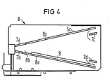
- Fig. 4 einen trichterförmigen Lichteintrittsschacht in Seitenansicht,
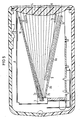
- Fig. 5 einen Schnitt V-V gem. Fig.1,
- Fig. 6,7 ein Fahrzeug mit der Sende- und Empfangseinrichtung in den jeweiligen Außenspiegeln und
- Fig. 8 eine schematische Darstellung im Schnitt.
- 1 a transmitting and receiving device seen from above, partially cut away,
- 2 a cover plate from behind,
- 3 seen the cover plate from the side,
- 4 is a funnel-shaped light inlet shaft in side view,
- Fig. 5 shows a section VV acc. Fig.1,
- Fig. 6.7 a vehicle with the transmitting and receiving device in the respective exterior mirrors and
- Fig. 8 is a schematic representation in section.
In Fig. 1 ist die Sende- und Empfangseinrichtung von oben gesehen, teilweise aufgerissen gezeigt. Innerhalb des Gehäuses 1 ist im linken, sich weiter nach hinten erstreckenden Bereich das Empfangsteil, im weniger tiefen Bereich sind rechts die Sendedioden 2 angeordnet. Davor befindet sich die Abdeckscheibe 4. Im Empfangsbereich ist der erfindungsgemäß ausgestaltete Lichteintrittsschacht angeordnet, in dessen hinterem Bereich, also im Bereich der Geräterückseite, die Empfangsdioden 3 angeordnet sind. Die zumindest im Empfangsbereich erforderliche Linse entfällt hier.In Fig. 1, the transmitting and receiving device is seen from above, partially shown in a tear. Within the housing 1, the receiving part is arranged in the left-hand region, which extends further to the rear, and in the less deep region, the transmitting
In Fig.2 und 3 ist die Abdeckscheibe 4 gezeigt. Dabei ist in Fig.2 die Abdeckscheibe von hinten gesehen, so daß deutlich im linken Bereich die Empfangsoptik 6 zu erkennen ist. Diese ist als sphärische Linse ausgebildet und einstückig mit der Abdeckscheibe 4 geformt. Sehr deutlich ist dies in der Seitenansicht der Abdeckscheibe 4 in der Fig.3 zu erkennen. Im Bereich der Sendedioden sind in diesem Ausführungsbeispiel 6 übereinander angeordnete, sich horizontal erstreckende, zylinderförmige Linsen 5 in der Abdeckscheibe 4 integriert. Die Zylinderlinsen 5 bewirken eine breite Abstrahlung im Horizontalwinkel, im Vertikalwinkel hingegen eine sehr schmale Abstrahlung, die beispielsweise nach oben und unten einen Halbwertswinkel von je ca. 3° aufweisen kann. Ohne diese Zylinderlinsen haben übliche Dioden einen Halbwertswinkel von jeweils 11°. Durch die erfindungsgemäße Ausgestaltung wird eine wesentliche bessere Ausbeute der Sendeenergie erreicht.2 and 3, the
In Fig. 4 ist der Lichteintrittsschacht 8 von der Seite gesehen gezeigt. Die Empfangsdioden 3 sind am Trichterende angeordnet. Die vertikalen Schirmbleche 7 weisen längs verlaufende Ausnehmungen 7a bis 7c auf, in denen das obere 8c- und das untere 8a-Schirmblech mit jeweiligen Nasen verrastbar ist. Im Nahbereich 8b der Empfangsdioden 3 befindet sich auf dem unteren Schirmblech 8a kein lichtabsorbierender Belag. Erst davor erstreckt sich der lichtabsobierende Belag 9, der beispielsweise aus schwarzem Samt sein kann, bis zur Trichteröffnung. Weitere Einzelheiten sind in der Schnittzeichnung in der Fig. 5 ersichtlich.4 shows the
In der Fig. 5 ist im Schnitt gesehen innerhalb des Gehäuses 1 der trichterförmige Lichteintrittschacht 8 angeordnet, der an seinem Trichterende die Empfangsdioden 3 aufweist. Die Abdeckscheibe 4 weist eine integrierte sphärische Linse 6 auf, die zum Schachtinneren zeigt. Der Schacht ist von zwei vertikalen Schirmblechen 7 und einem oberen Schirmblech 8c und einem unteren Schirmblech 8a gebildet. In den Ausnehmungen 7a bis 7d ist das obere und das untere Schirmblech mit jeweiligen Rastnasen verrastet. Dabei ist die eine Ausnehmung 7a und die entsprechende Rastnase länger ausgebildet als die übrigen, so daß das obere Schirmblech 8c, das auf der Innenseite zur Erzielung einer hohen Reflexion plattiert ist, beim Einbau nicht verwechselt werden kann, d.h. mit der reflektierenden Seite nach oben eingebaut werden kann. Diese längere Ausnehmung 7a ist beispielsweise in dem linken vertikalen Schirmblech eingebracht. Die Ausnehmung 7b ist nicht in der Fluchtlinie der übrigen Ausnehmungen verlaufend, so daß beim Verrasten der Rastnase eine kraftschlüssige Verbindung entsteht. Im Bereich der Frontseite ist ein zusätzliches Ausnehmungspaar 7c und 7b gezeigt, in das das obere und untere Schirmblech eingerastet werden kann, wenn der Öffnungswinkel geringer als hier dargestellt sein soll. Die Innenseite des unteren Schirmblechs 8a weist einen nichtabsorbierenden Belag 9 auf, der sich jedoch nicht unmittelbar bis zu den Empfangsdioden 3 erstreckt. Der Nahbereich 8b kann ebenfalls eine reflektierende Schicht aufweisen, so daß flach einfallende Infrarotstrahlung in diesem Nahbereich noch zu den Empfangs dioden 3 reflektiert werden. In Fig. 5 sind noch eine Reihe von einfallenden Lichtstrahlen eingezeichnet, die entweder direkt zu den Empfangsdioden 3 oder über Reflexion an dem oberen Schirmblech 8c zu den Empfangsdioden 3 gelangen.5, the funnel-shaped
Fig. 6 zeigt ein Fahrzeug FZ in Vorderansicht mit seitlichen Außenspiegeln AS, in die die Sende- und Empfangseinrichtung eingebaut ist und in Fahrtrichtung eine lichtdurchlässige Frontscheibe 4 aufweist.Fig. 6 shows a vehicle FZ in front view with side mirrors AS, in which the transmitting and receiving device is installed and has a
Fig. 7 zeigt in Draufsicht ein Fahrzeug FZ mit den an den linken und rechten Seitenspiegeln AS angeordneten Sende- und Empfangseinrichtungen. Dabei sind die Infrarot-Sende- und -empfangsstrahlungen SS und ES angedeutet.7 shows a plan view of a vehicle FZ with the transmitting and receiving devices arranged on the left and right side mirrors AS. The infrared transmission and reception radiation SS and ES are indicated.
In Fig. 8 ist das Gehäuse 1 eines Außenspiegels AS schematisch im Schnitt, jedoch ohne den eigentlichen Spiegel, dargestellt. Es ist hier nur eine Prinzipdarstellung gezeigt, die die wesentlichen erfindungsmäßigen Elemente aufzeigen soll. Im Einzelfall wird das Gehäuse 1 des Außenspiegels AS mit den integrierten Empfangs- und Sendelinsen an das jeweils fahrzeugspezifische Spiegelmodell angepaßt sein. Zumindest an einer Stelle in der Fahrtrichtung ist die Wandung des Gehäuses 1 aus infrarotdurchlässigem Material zu einer Sende- und Empfangslinse ausgeformt. Hier ist nur die Empfangslinse 6 gezeigt. Sie fokkusiert die Infrarotstrahlung ES auf die Empfangsdioden 3, hier nur eine dargestellt. Die Empfangsdioden 3 sowie die hier nicht dargestellten Sendedioden (2) sind auf einer Leiterplatten-Baugruppe 10 angeordnet, die auf entsprechenden Stützen 14 angeschraubt (10c) ist. Dabei können die Stützen bzw. die Distanzträger 14 an dem Gehäuse 1 mit angeformt sein.8, the housing 1 of an outside mirror AS is shown schematically in section, but without the actual mirror. Only a basic illustration is shown here, which is intended to show the essential elements according to the invention. In individual cases, the housing 1 of the outside mirror AS with the integrated receiving and transmitting lenses will be adapted to the vehicle-specific mirror model. At least at one point in the direction of travel, the wall of the housing 1 is formed from an infrared-transparent material to form a transmitting and receiving lens. Only the receiving
In einer Weiterbildung der Erfindung können ebenfalls am Gehäuse 1 angeformte Stege bzw. Wände 8c und 8a als "Schirmbleche" ausgebildet sein und einen Nichteintrittsschacht 8 für die Empfangsdioden 3 bilden. Diese angeformten Stege 8c und 8a sind jedoch nicht infrarotlichtdurchlässig ausgebildet.In a further development of the invention, webs or
Dabei kann der untere Steg 8a mit einem lichtabsorbierenden Material 9 beschichtet sein.The
1 Gehäuse
2 Sendedioden
3 Empfangsdioden
4 Abdeckscheibe
5 Sendelinsen
6 Empfangslinse
7 vertikale Schirmbleche (Seitenwände)
7a-7d Ausnehmungen
8 Lichteintrittsschacht
8a untere Wand, Bodenblech
8b Nahbereich
8c oberes Schirmblech (obere Wand)
9 lichtabsorbierender Belag (Samt)
10 Leiterplatten-Baugruppe
10c Befestigungsschrauben
14 Distanzträger
FZ Kraftfahrzeug
AS Außenspiegel
SS Sendestrahlung
ES Empfangsstrahlung
IB (Informations-) Bake
1 housing
2 transmission diodes
3 receiving diodes
4 cover plate
5 transmit lenses
6 receiving lens
7 vertical shield plates (side walls)
7a-7d recesses
8 light entry shaft
8a lower wall, floor panel
8b close range
8c upper shield plate (upper wall)
9 light-absorbing covering (velvet)
10 circuit board assembly
10c mounting screws
14 spacers
FZ motor vehicle
AS wing mirror
SS broadcast radiation
ES reception radiation
IB (information) beacon
Claims (16)
dadurch gekennzeichnet, daß die Abdeckscheibe (4) zugleich als integrierte Sende- und Empfangsoptik einstückig mit zumindest einer Empfangslinse (6) und mehreren Sendelinsen (5) ausgebildet ist, daß auf der Innenseite des Lichteintrittsschacht (8) die untere Wand (8a) lichtabsorbierend und die üblichen Wände (7,8c) lichtreflektierend ausgebildet sind, und daß die Sende- und Empfangseinrichtung mit der Abdeckscheibe (4) in Fahrtrichtung zu den ortsfesten Baken (IB) im Fahrzeug (FZ) angebracht ist.1. Transmitting and receiving device for the transmission of information by means of light beams, preferably in the infrared range, between fixed beacons (IB) and portable motor vehicles (FZ), with transmitting and receiving diodes (2, 3) on a printed circuit board in a common housing (1). Assembly (10) with beam direction (SS, ES) to a translucent front wall, which is formed by a cover plate (4), are arranged, the area in front of the receiving diodes (3) having a greater depth and a funnel-shaped light entry shaft (8) which is essentially formed from two opposite walls (7, 8a, 8c), and wherein, in addition to the receiving diodes (3), the transmitting diodes (2) are arranged in a region which has a smaller depth,
characterized in that the cover plate (4) is simultaneously formed in one piece with at least one receiving lens (6) and several transmitting lenses (5) as integrated transmitting and receiving optics, that on the inside of the light entry shaft (8) the lower wall (8a) is light-absorbing and the usual walls (7, 8c) are designed to reflect light, and that the transmitting and receiving device with the cover plate (4) is attached in the direction of travel to the stationary beacons (IB) in the vehicle (FZ).
dadurch gekennzeichnet, daß die Abdeckscheibe (4) auf der Innenseite plan und die Innenseite linsenförmig ausgebildet ist, wobei die Empfangslinse (6) und die Sendelinsen (5) nebeneinander oder übereinander angeordnet sind.2. Transmitting and receiving device according to claim 1,
characterized in that the cover plate (4) is flat on the inside and the inside is lenticular, the receiving lens (6) and the transmitting lenses (5) being arranged side by side or one above the other.
dadurch gekennzeichnet, daß die Abdeckscheibe (4) im Bereich der Empfangsdioden (3) eine sphärisch ausgebildete Empfangslinse (6) und im Bereich der Sendedioden (2) horizontal verlaufende, zylinderförmig ausgebildete Sendelinsen (5) aufweist.3. Transmitting and receiving device according to claim 1 or 2,
characterized in that the cover disk (4) has a spherically shaped receiving lens (6) in the area of the receiving diodes (3) and cylindrical, cylindrical shaped sending lenses (5) in the area of the sending diodes (2).
dadurch gekennzeichnet, daß den übereinanderliegenden Reihen von Sendedioden (2) jeweils eine zylinderförmige Linse längs einer Sendediodenreihe zugeordnet ist.4. transmitting and receiving device according to claim 3,
characterized in that the rows of transmitting diodes (2) one above the other are each assigned a cylindrical lens along a row of transmitting diodes.
dadurch gekennzeichnet, daß an der Innenseite entweder an der Abdeckscheibe (4) oder am Gehäuse (1) zumindest zwei Distanzträger (14) zur Aufnahme der Leiterplatten-Baugruppe (10) angeformt sind.5. Transmitting and receiving device according to claim 3 or 4,
characterized in that at least two spacers (14) for receiving the printed circuit board assembly (10) are integrally formed on the inside, either on the cover plate (4) or on the housing (1).
dadurch gekennzeichnet, daß die Wände des Lichteintrittsschachts (8) von Schirmblechen gebildet sind, wobei das lichtabsorbierende Bodenblech (8a) einen absorbierenden Belag (9), z.B. schwarzen Samt, aufweist und die reflektierenden Schirmbleche auf den Innenseiten plattiert sind.6. transmitting and receiving device according to claim 1,
characterized in that the walls of the light entry shaft (8) are formed by shielding plates, the light-absorbing base plate (8a) having an absorbent coating (9), for example black velvet, and the reflecting shielding plates are plated on the inside.
dadurch gekennzeichnet, daß sich der absorbierende Belag (9) bis dicht an die Frontseite (4), jedoch nicht bis in den Nahbereich (8b) der Empfangsdioden (3), erstreckt.7. transmitting and receiving device according to claim 6,
characterized in that the absorbent coating (9) extends close to the front (4), but not to the vicinity (8b) of the receiving diodes (3).
dadurch gekennzeichnet, daß das obere und das untere Schirmblech (8c,8a) mit angeformten Nasen, die im Front- und im Rückseitenbereich angeordnet sind, in zugehörige Ausnehmungen (7a bis 7b) der vertikalen Schirmbleche (7) verrastbar sind.8. transmitting and receiving device according to claim 6,
characterized in that the upper and lower shield plates (8c, 8a) with molded lugs, which are arranged in the front and in the rear area, can be latched into corresponding recesses (7a to 7b) of the vertical shield plates (7).
dadurch gekennzeichnet, daß zumindest das obere Schirmblech (8c) im Rückseitenbereich an einer Seite eine längere Rastnase und das vertikale Schirmblech (7) eine entsprechende, längs verlaufende Ausnehmung (7a) aufweist.9. transmitting and receiving device according to claim 8,
characterized in that at least the upper shield plate (8c) has a longer latching lug on one side in the rear area and the vertical shield plate (7) has a corresponding, longitudinally extending recess (7a).
dadurch gekennzeichnet, daß die vertikalen Schirmbleche (7) im Frontseitenbereich mehrere Ausnehmungspaare (7c und 7d) aufweisen.10. transmitting and receiving device according to claim 8,
characterized in that the vertical shield plates (7) have a plurality of recess pairs (7c and 7d) in the front area.
dadurch gekennzeichnet, daß jedes vertikale Schirmblech (7) zumindest eine Ausnehmung (7b) aufweist, die nicht in der Fluchtlinie der längs verlaufenden Ausnehmungen verläuft.11. Transmitting and receiving device according to claim 8,
characterized in that each vertical screen plate (7) has at least one recess (7b) which does not run in the line of alignment of the longitudinal recesses.
daß sie hinter der Windschutzscheibe vor dem Innenspiegel angeordnet ist.12. Transmitting and receiving device according to one of the preceding claims, characterized in that
that it is located behind the windshield in front of the inside mirror.
daß sie in zumindest einem seitlichen Außenspiegel (AS) des Fahrzeugs (FZ) angeordnet ist, und daß das feststehende Gehäuse (1) des Außenspiegels (AS) zugleich das Gehäuse (1) für die Sende- und Empfangseinrichtung bildet.13. Transmitting and receiving device according to one of claims 1 to 11, characterized in
that it is arranged in at least one side outside mirror (AS) of the vehicle (FZ), and that the fixed housing (1) of the outside mirror (AS) also forms the housing (1) for the transmitting and receiving device.
dadurch gekennzeichnet, daß sie jeweils im rechten und im linken Außenspiegel (AS) angeordnet ist.14. Transmitting and receiving device according to claim 13,
characterized in that it is arranged in the right and left exterior mirrors (AS).
dadurch gekennzeichnet, daß das feststehende Gehäuse (1) des Außenspiegels (AS) aus infrarotlichtdurchlässigem Werkstoff mit integrierter Sende- und Empfangsoptik (5,6) ausgebildet ist, und daß dahinter die zugeordneten Sende- und Empfangsdioden (2,3) auf der Leiterplatten-Baugruppe (10) angebracht sind, wobei die Leiterplatte auf den angeformten Distanzträger (14) befestigt ist.15. Transmitting and receiving device according to claim 13 or 14,
characterized in that the fixed housing (1) of the exterior mirror (AS) is made of infrared-transparent material with integrated transmission and reception optics (5, 6), and that behind it the assigned transmission and reception diodes (2, 3) on the printed circuit board Assembly (10) are attached, wherein the circuit board is attached to the molded spacer (14).
daß an der Innenseite des Gehäuses (1) ein oberer und ein unterer Steg (8c,8a) angeformt sind, die lichtundurchlässig und als Lichteintrittsschacht (8) ausgebildet sind.16. Transmitting and receiving device according to one of the preceding claims, characterized in that
that an upper and a lower web (8c, 8a) are formed on the inside of the housing (1), which are opaque and designed as a light entry shaft (8).
Applications Claiming Priority (6)
| Application Number | Priority Date | Filing Date | Title |
|---|---|---|---|
| DE8713877U | 1987-10-15 | ||
| DE8713877U DE8713877U1 (en) | 1987-10-15 | 1987-10-15 | |
| DE8713878U DE8713878U1 (en) | 1987-10-15 | 1987-10-15 | |
| DE8713878U | 1987-10-15 | ||
| DE8804737U | 1988-04-11 | ||
| DE8804737U DE8804737U1 (en) | 1988-04-11 | 1988-04-11 |
Publications (2)
| Publication Number | Publication Date |
|---|---|
| EP0312010A2 true EP0312010A2 (en) | 1989-04-19 |
| EP0312010A3 EP0312010A3 (en) | 1989-08-02 |
Family
ID=27207803
Family Applications (1)
| Application Number | Title | Priority Date | Filing Date |
|---|---|---|---|
| EP88116932A Withdrawn EP0312010A3 (en) | 1987-10-15 | 1988-10-12 | Transmitter and receiver device for the transmission of information by light beams |
Country Status (1)
| Country | Link |
|---|---|
| EP (1) | EP0312010A3 (en) |
Cited By (4)
| Publication number | Priority date | Publication date | Assignee | Title |
|---|---|---|---|---|
| US5383500A (en) * | 1992-03-19 | 1995-01-24 | Shell Oil Company | Automatic refuelling system |
| EP0814343A2 (en) * | 1996-06-17 | 1997-12-29 | Harness System Technologies Research, Ltd. | Optical head of optical beacon |
| DE19801884A1 (en) * | 1998-01-20 | 1999-07-22 | Mannesmann Vdo Ag | CCTV monitoring system for blind spots around motor vehicle |
| US6596713B1 (en) | 1994-09-14 | 2003-07-22 | Schering Aktiengesellschaft | Steroid esters and amides, process for their production and their pharmaceutical use |
Citations (3)
| Publication number | Priority date | Publication date | Assignee | Title |
|---|---|---|---|---|
| FR2468172A1 (en) * | 1979-10-23 | 1981-04-30 | Robert Philippe | Safety device for motor vehicles altering direction - measures distance to following vehicle and uses RPM and acceleration to compute whether manoeuvre can be safety attempted |
| DE3248544A1 (en) * | 1982-12-29 | 1984-07-12 | Siemens AG, 1000 Berlin und 8000 München | System for information transmission by means of infrared radiation |
| EP0235678A1 (en) * | 1986-02-21 | 1987-09-09 | Siemens Aktiengesellschaft | Transmitting and receiving device to be fitted in a vehicle |
-
1988
- 1988-10-12 EP EP88116932A patent/EP0312010A3/en not_active Withdrawn
Patent Citations (3)
| Publication number | Priority date | Publication date | Assignee | Title |
|---|---|---|---|---|
| FR2468172A1 (en) * | 1979-10-23 | 1981-04-30 | Robert Philippe | Safety device for motor vehicles altering direction - measures distance to following vehicle and uses RPM and acceleration to compute whether manoeuvre can be safety attempted |
| DE3248544A1 (en) * | 1982-12-29 | 1984-07-12 | Siemens AG, 1000 Berlin und 8000 München | System for information transmission by means of infrared radiation |
| EP0235678A1 (en) * | 1986-02-21 | 1987-09-09 | Siemens Aktiengesellschaft | Transmitting and receiving device to be fitted in a vehicle |
Cited By (6)
| Publication number | Priority date | Publication date | Assignee | Title |
|---|---|---|---|---|
| US5383500A (en) * | 1992-03-19 | 1995-01-24 | Shell Oil Company | Automatic refuelling system |
| US6596713B1 (en) | 1994-09-14 | 2003-07-22 | Schering Aktiengesellschaft | Steroid esters and amides, process for their production and their pharmaceutical use |
| EP0814343A2 (en) * | 1996-06-17 | 1997-12-29 | Harness System Technologies Research, Ltd. | Optical head of optical beacon |
| EP0814343A3 (en) * | 1996-06-17 | 1998-08-05 | Harness System Technologies Research, Ltd. | Optical head of optical beacon |
| US5999296A (en) * | 1996-06-17 | 1999-12-07 | Harness System Technologies Research Ltd. | Optical head of optical beacon |
| DE19801884A1 (en) * | 1998-01-20 | 1999-07-22 | Mannesmann Vdo Ag | CCTV monitoring system for blind spots around motor vehicle |
Also Published As
| Publication number | Publication date |
|---|---|
| EP0312010A3 (en) | 1989-08-02 |
Similar Documents
| Publication | Publication Date | Title |
|---|---|---|
| DE69918048T2 (en) | Gate for motor vehicle with system for object detection | |
| DE2648604C3 (en) | Lens for a light transmitter in a remote control system | |
| DE102013012789A1 (en) | Scanning optoelectronic detection device and motor vehicle with such a detection device | |
| DE60127130T2 (en) | OPTICAL RAIN SENSOR | |
| WO2013079331A1 (en) | Optical measuring device | |
| DE102012212150B4 (en) | Laser radar device arranged between a license plate and a vehicle body | |
| EP2112039A2 (en) | Optical sensor device | |
| EP1836462B1 (en) | Sensor device, especially for a motor vehicle | |
| DE4104233A1 (en) | REFLECTION TYPE VEHICLE DISPLAY DEVICE | |
| EP0843180A1 (en) | Distance measurement by laser | |
| DE112019000621T5 (en) | LIDAR DEVICE | |
| EP2176098A1 (en) | Device for determining the reflective properties of a boundary | |
| DE102019218005A1 (en) | LIDAR sensor | |
| EP2833161A1 (en) | Optoelectronic measuring device for a motor vehicle and scan sensor for the same | |
| EP2737334A1 (en) | Optical measuring device for a vehicle | |
| EP0330165B1 (en) | Infrared band information transmission emitting and receiving device | |
| EP0312010A2 (en) | Transmitter and receiver device for the transmission of information by light beams | |
| DE10214572A1 (en) | Precipitation sensor | |
| EP2185917B1 (en) | Optical rain sensor apparatus for a motor vehicle | |
| EP0235678A1 (en) | Transmitting and receiving device to be fitted in a vehicle | |
| DE102016117853A1 (en) | Transmitting device for an optical detection device, optical detection device, motor vehicle and method | |
| DE102019106544B4 (en) | Ambient light sensing device, rain light sensor for use on a windshield and motor vehicle | |
| DE4222659A1 (en) | Optical scanner for range finder for obstruction warning esp. for driverless transport system - has fixed and coaxial emitters and receiver, and rotating optical system located in mirrored box and consisting of lenses and inclined mirrors which focus received beam on axis where receiver is located | |
| EP0967583B1 (en) | Opto-electronic sensor device | |
| DE2918822A1 (en) | Improved visibility external rear view mirror - has safety arrangement of two mirrors on outside edge for forward view |
Legal Events
| Date | Code | Title | Description |
|---|---|---|---|
| PUAI | Public reference made under article 153(3) epc to a published international application that has entered the european phase |
Free format text: ORIGINAL CODE: 0009012 |
|
| AK | Designated contracting states |
Kind code of ref document: A2 Designated state(s): DE ES FR GB IT NL |
|
| PUAL | Search report despatched |
Free format text: ORIGINAL CODE: 0009013 |
|
| AK | Designated contracting states |
Kind code of ref document: A3 Designated state(s): DE ES FR GB IT NL |
|
| 17P | Request for examination filed |
Effective date: 19900129 |
|
| 17Q | First examination report despatched |
Effective date: 19921005 |
|
| STAA | Information on the status of an ep patent application or granted ep patent |
Free format text: STATUS: THE APPLICATION IS DEEMED TO BE WITHDRAWN |
|
| 18D | Application deemed to be withdrawn |
Effective date: 19930713 |