EP0311497B1 - Tilting actuating device for the outlet valve of a flushing reservoir - Google Patents
Tilting actuating device for the outlet valve of a flushing reservoir Download PDFInfo
- Publication number
- EP0311497B1 EP0311497B1 EP88402495A EP88402495A EP0311497B1 EP 0311497 B1 EP0311497 B1 EP 0311497B1 EP 88402495 A EP88402495 A EP 88402495A EP 88402495 A EP88402495 A EP 88402495A EP 0311497 B1 EP0311497 B1 EP 0311497B1
- Authority
- EP
- European Patent Office
- Prior art keywords
- lever
- stem
- operating member
- rod
- axis
- Prior art date
- Legal status (The legal status is an assumption and is not a legal conclusion. Google has not performed a legal analysis and makes no representation as to the accuracy of the status listed.)
- Expired - Lifetime
Links
- 238000011010 flushing procedure Methods 0.000 title claims 2
- XLYOFNOQVPJJNP-UHFFFAOYSA-N water Substances O XLYOFNOQVPJJNP-UHFFFAOYSA-N 0.000 claims description 10
- 238000006073 displacement reaction Methods 0.000 claims description 5
- 239000011435 rock Substances 0.000 claims 2
- 208000031968 Cadaver Diseases 0.000 description 6
- 210000000056 organ Anatomy 0.000 description 3
- 238000000034 method Methods 0.000 description 2
- 230000000087 stabilizing effect Effects 0.000 description 2
- RRHGJUQNOFWUDK-UHFFFAOYSA-N Isoprene Chemical compound CC(=C)C=C RRHGJUQNOFWUDK-UHFFFAOYSA-N 0.000 description 1
- 241001080024 Telles Species 0.000 description 1
- 240000008042 Zea mays Species 0.000 description 1
- 239000000919 ceramic Substances 0.000 description 1
- 229920001971 elastomer Polymers 0.000 description 1
- 239000002991 molded plastic Substances 0.000 description 1
- 229920001195 polyisoprene Polymers 0.000 description 1
- 238000007789 sealing Methods 0.000 description 1
Images
Classifications
-
- E—FIXED CONSTRUCTIONS
- E03—WATER SUPPLY; SEWERAGE
- E03D—WATER-CLOSETS OR URINALS WITH FLUSHING DEVICES; FLUSHING VALVES THEREFOR
- E03D1/00—Water flushing devices with cisterns ; Setting up a range of flushing devices or water-closets; Combinations of several flushing devices
- E03D1/02—High-level flushing systems
- E03D1/14—Cisterns discharging variable quantities of water also cisterns with bell siphons in combination with flushing valves
- E03D1/142—Cisterns discharging variable quantities of water also cisterns with bell siphons in combination with flushing valves in cisterns with flushing valves
-
- E—FIXED CONSTRUCTIONS
- E03—WATER SUPPLY; SEWERAGE
- E03D—WATER-CLOSETS OR URINALS WITH FLUSHING DEVICES; FLUSHING VALVES THEREFOR
- E03D1/00—Water flushing devices with cisterns ; Setting up a range of flushing devices or water-closets; Combinations of several flushing devices
- E03D1/02—High-level flushing systems
- E03D1/14—Cisterns discharging variable quantities of water also cisterns with bell siphons in combination with flushing valves
- E03D2001/147—Cisterns discharging variable quantities of water also cisterns with bell siphons in combination with flushing valves having provisions for active interruption of flushing
Definitions
- the present invention relates to a device for actuating the valve for emptying a flush tank, in particular a flush tank for toilet bowls.
- the flush tanks are all equipped with a draining device; they are generally located either in height and the emptying device is actuated by a lever extended by a chain or other known means, or just above the toilet bowl and are generally covered with a cover provided with a button that must be pushed in or pulled out to activate the drain.
- the devices actuated by a zipper if they make it possible to interrupt the flow by pushing the zipper down, have the drawback of being fragile: they twist, are torn off or broken.
- This device provides a member on the side of the tank, tilting around an axis, in two positions.
- the organ is connected to the axis of the valve by an arm which makes lever so that one position of the organ actuates the lever which opens the valve, and the other position of the organ actuates inversely the lever , which closes the valve.
- this device cannot be placed on the covers with axial opening.
- the actuating rod be vertical, with or without a sheath: it is possible to tilt it, even to the horizontal, and to transmit the movement produced by the tilting on the lever equivalently.
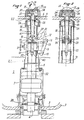
- FIG. 1 illustrates the interior of a flush tank 1, crossed by the actuating device of the drain valve.
- This tank 1 comprises a tank 2 with a bottom 3, pierced with an opening 4 or drain plug, and a cover 5 pierced with an opening 6 intended to receive the operating member 16 of the actuating device.
- the rod-lever link 19 is located between the two ends 13, 14 of the lever 12, on the side of the hinge pin 17 in order to increase the displacement of the end 14 of the lever when the rod-lever link moves, this reduction allows the opening and closing of the valve 7.
- the length of the lever is calculated so that the reduction is adapted to the flow of water.
- control rod 15 is guided in a sheath 18, integral with the reservoir 1 and stationary, and the link 19 rod-lever is produced by means of at least one finger 20 carried by the rod 15 and sliding in a slot 21 oblong to the lever 12.
- the mechanical link 29 rod-operating member is produced by a link 28, integral with the operating member 16 and cooperating with a lateral extension of the rod 15 in the form of a ramp 30.
- the operating member is pivotally mounted around a horizontal axis 31, and the link 28 is mounted offset relative to this pivoting axis 31 and relative to the axis 32 of the control rod 15.
- the member 16 When the member 16 switches from the closed position 27 to the open position 26, it drives the link 28 which moves with the ramp; the end of the rod travels in a circular path and slides on the underside of the ramp by lifting it with the rod.
- the displacement 26 ′ of the rod necessarily involves that of the nut 20 and the fingers 21 which raise the lever 12; this movement is transmitted to tube 8 and the valve opens.
- the device makes it possible to interrupt the flow of water during the emptying of the tank: the operating member 16 being in the open position 26, the fact of tilting it in the opposite closed position 27, drives the ramp 30 downwards, and with it the rod 15 (closing movement 27 ′), the lever 12, the connecting rod 9, the tube 8 and the valve 7 closes (27 ⁇ ).
- the operating member can have various conformations: it is only preferred to tilt and comprising a connecting rod offset relative to the axis 31 of tilting.
- the operating member 16 comprises a circular base 34 and a hemispherical upper face recessed symmetrically with respect to the tilting axis 31; this hemisphere 35 is pivotally mounted, by two pins 36 in a housing 37 secured to the sheath 18.
- the sheath 18 and the housing 37 are formed in a single block, for example in molded plastic.
- the recess is cylindrical, with an axis parallel to the tilting axis 31 so that at each of the positions 26 or 27, the member has an edge which merges with the edge of the housing 37 or of any other surface. immediately adjacent, the other edge projecting and having a bearing face for tilting.
Landscapes
- Life Sciences & Earth Sciences (AREA)
- Engineering & Computer Science (AREA)
- Hydrology & Water Resources (AREA)
- Public Health (AREA)
- Water Supply & Treatment (AREA)
- Health & Medical Sciences (AREA)
- Mechanically-Actuated Valves (AREA)
- Sanitary Device For Flush Toilet (AREA)
- Electrical Discharge Machining, Electrochemical Machining, And Combined Machining (AREA)
- Multiple-Way Valves (AREA)
- Self-Closing Valves And Venting Or Aerating Valves (AREA)
- Sink And Installation For Waste Water (AREA)
- Fluid-Driven Valves (AREA)
Abstract
Description
La présente invention se rapporte à un dispositif d'actionnement de la soupape de vidange d'un réservoir de chasse, notamment d'un réservoir de chasse d'eau de cuvette de WC.The present invention relates to a device for actuating the valve for emptying a flush tank, in particular a flush tank for toilet bowls.
Les réservoirs de chasse d'eau sont tous équipés d'un dispositif de vidange; ils sont généralement situés soit en hauteur et le dispositif de vidange est actionné par un levier prolongé d'une chaînette ou autre moyen connu, soit juste au-dessus de la cuvette de WC et sont généralement recouverts d'un couvercle muni d'un bouton de commande qu'il faut enfoncer ou tirer pour actionner la vidange.The flush tanks are all equipped with a draining device; they are generally located either in height and the emptying device is actuated by a lever extended by a chain or other known means, or just above the toilet bowl and are generally covered with a cover provided with a button that must be pushed in or pulled out to activate the drain.
Les dispositifs de vidange situés en hauteur, s'ils fonctionnent généralement bien, sont encombrants et ne permettent pas d'interrompre l'écoulement car on ne peut refermer manuellement la soupape avec la chaînette de commande. Ceci présente un inconvénient car bien souvent une partie du volume d'eau du réservoir suffirait au rinçage de la cuvette, ce qui permettrait d'économiser une quantité importante d'eau.The emptying devices located at height, if they generally work well, are bulky and do not allow the flow to be interrupted because the valve cannot be closed manually with the control chain. This has a disadvantage because very often part of the volume of water in the tank would be sufficient to rinse the bowl, which would save a significant amount of water.
Les dispositifs actionnés par une tirette, s'ils permettent d'interrompre l'écoulement en repoussant la tirette vers le bas, présentent cependant l'inconvénient d'être fragiles: ils se tordent, sont arrachés ou cassés.The devices actuated by a zipper, if they make it possible to interrupt the flow by pushing the zipper down, have the drawback of being fragile: they twist, are torn off or broken.
Pour remédier à cet inconvénient, des dispositifs de vidange actionnés par bouton poussoir ont été créés. Cette technique est caractérisée par l'inversion du mouvement: la soupape est soulevée (et ouverte) en poussant un bouton vers le bas sur une courte distance (mouvements relatifs soupape-bouton inversés) lequel bouton revient ensuite sous l'action d'un ressort, tout en laissant l'eau s'évacuer. Dans cette technique il existe aussi des boutons poussoirs à simple effet, dont la mécanique ne permet que l'ouverture de la soupape; ces boutons ont l'avantage d'être peu coûteux et robustes, mais ils ne permettent pas d'interrompre l'écoulement.To remedy this drawback, emptying devices actuated by push button have been created. This technique is characterized by reversing the movement: the valve is lifted (and opened) by pushing a button down a short distance (relative valve-button movements reversed) which button then returns under the action of a spring, while letting the water drain out. In this technique there are also single acting push buttons, the mechanics of which only allow the valve to open; these buttons have the advantage of being inexpensive and robust, but they do not allow the flow to be interrupted.
Il existe aussi des boutons poussoirs à double effet, permettant dans un premier temps d'ouvrir la soupape (mouvement vers le haut) en poussant le bouton (mouvement vers le bas) et, dans un deuxième temps de fermer la soupape (mouvement vers le bas) avant la fin de l'écoulement en poussant une deuxième fois le bouton (mouvement vers le bas); un tel dispositif est décrit par exemple dans le brevet FR 2 548 328: un bouton poussoir se déplace verticalement et vient appuyer sur un levier relié à une biellette qui commande l'ouverture ou la fermeture de la vidage. Selon la position du levier, c'est-à-dire selon que la soupape est ouverte ou fermée le bouton en se déplaçant vers le bas abaisse ou lève le levier, et ainsi peut interrompre l'écoulement de l'eau. Pour que le même déplacement vertical du bouton puisse donner deux résultats opposés (ouverture-fermeture) le dispositif comporte un organe d'extrémité qui pivote latéralement entre deux positions, une chaque fonction.There are also double-acting pushbuttons, allowing you to open the valve first (upward movement) by pushing the button (downward movement) and, secondly to close the valve (upward movement). down) before the end of the flow by pushing the button a second time (downward movement); such a device is described for example in patent FR 2 548 328: a push button moves vertically and comes to press on a lever connected to a link which controls the opening or closing of the emptying. Depending on the position of the lever, that is to say depending on whether the valve is open or closed, the button moving downwards lowers or lifts the lever, and thus can interrupt the flow of water. So that the same vertical movement of the button can give two opposite results (open-close) the device comprises an end member which pivots laterally between two positions, one each function.
Ces dispositifs présentent cependant l'inconvénient d'être complexes (en raison de la mécanique d'inversion du mouvement), encombrants, et d'être difficiles à adapter aux différentes hauteurs de réservoir.However, these devices have the drawback of being complex (due to the mechanics of reversing the movement), bulky, and of being difficult to adapt to the different heights of the tank.
En outre, il existe une sorte de standard dans les couvercles de cuve en céramique, ce standard étant caractérisé par des dimensions et par une ouverture centrale, dans l'axe de la soupape de vidange, destinée au passage de l'organe de manoeuvre du dispositif de vidange.In addition, there is a kind of standard in ceramic tank covers, this standard being characterized by dimensions and by a central opening, in the axis of the drain valve, intended for the passage of the operating member of the emptying device.
Les constructeurs d'appareils de vidange cherchent donc à réaliser des dispositifs destinés à être montés sur ces couvercles à ouverture axiale; et les dispositifs précédemment évoqués, à bouton poussoir en font partie.The manufacturers of emptying apparatuses therefore seek to produce devices intended to be mounted on these covers with axial opening; and the aforementioned push button devices are part of it.
Il existe d'autres dispositifs permettant d'interrompre simplement la vidange, notamment le dispositif à bascule décrit au brevet DE 3 605 188.There are other devices making it possible to simply interrupt the emptying, in particular the rocking device described in patent DE 3,605,188.
Ce dispositif prévoit un organe sur le côté de la cuve, basculant autour d'un axe, sur deux positions. L'organe est relié à l'axe de la soupape par un bras qui fait levier de telle sorte qu'une position de l'organe actionne le levier qui ouvre la soupape, et l'autre position de l'organe actionne inversement le levier, ce qui ferme la soupape. Mais ce dispositif ne peut être disposé sur les couvercles à ouverture axiale.This device provides a member on the side of the tank, tilting around an axis, in two positions. The organ is connected to the axis of the valve by an arm which makes lever so that one position of the organ actuates the lever which opens the valve, and the other position of the organ actuates inversely the lever , which closes the valve. However, this device cannot be placed on the covers with axial opening.
Un autre dispositif permettant l'interruption d'une vidange en cours est décrit dans le document US-A-4.527.296 correspondant au préambule de la revendication 1. Il s'agit d'un dispositif du type à bouton poussoir (le bouton est actionné vers le bas pour l'ouverture de la soupape de vidange) et à tirette (le bouton est actionné vers le haut pour l'interruption de vidange) et comporte une cuve dont le fond est percé d'une ouverture de vidange, et un couvercle percé d'une ouverture centrale et traversé par l'organe de manoeuvre. Cependant ce dispositif est complexe car les différents mouvements d'ouverture et de fermeture sont exécutés par des pièces différentes, d'où une mécanique assez compliquée.Another device allowing the interruption of a draining in progress is described in the document US-A-4,527,296 corresponding to the preamble of
La présente invention a pour objectif de résoudre ces inconvénients. Elle a pour objet un dispositif de vidange de réservoir de chasse d'eau de cuvette de WC pour réservoir comportant une cuve avec un fond percé d'une ouverture de vidange et un couvercle percé d'une ouverture centrale destinée à recevoir l'organe de manoeuvre, ledit organe comportant:
- un corps monté rigidement sur son fond,
- une soupape portée par un tube vertical déplaçable axialement dans le corps du dispositif,
- une bielle, décalée par rapport à l'axe du tube, destinée à commander les déplacements dudit tube,
- un levier de manoeuvre de la bielle, articulé sur un axe horizontal,
- une tige de manoeuvre du levier, située sensiblement dans l'axe du tube, liée mécaniquement d'une part au levier, d'autre part à l'organe de manoeuvre, et guidée dans une gaine montée solidaire du réservoir et immobile transversalement, caractérisée en ce que:
- l'organe de manoeuvre bascule entre deux positions stables, l'une d'ouverture, l'autre de fermeture de la soupape,
- la liaison mécanique entre la tige et le levier est réalisée au moyen d'un doigt porté par la tige et coulissant dans une lumière oblongue du levier, et en ce que la liaison mécanique, entre la tige et l'organe de manoeuvre est assurée par l'intermédiaire d'une biellette, solidaire de l'organe de manoeuvre et coopérant avec une rampe portée par la tige.
Selon d'autres caractéristiques avantageuses du dispositif: - l'organe de manoeuvre est monté basculant autour d'un axe horizontal.
- la biellette est décalée par rapport à l'axe de basculement de l'organe de manoeuvre et à l'axe de la tige de commande.
- la lumière oblongue est située entre l'axe de pivotement du levier et son extrémité opposée d'articulation à la bielle.
- la tige comporte une noix mobile le long de la tige par filetage et portant le doigt de liaison, destinée à adapter la position dudit doigt le long de la tige, c'est-à-dire la distance de la liaison "tige-levier" à la liaison "tige-organe de manoeuvre" aux dimensions du réservoir.
- le levier comporte deux bras parallèles identiques, un de chaque côté de la tige.
- en fin de vidange, la fermeture automatique de la soupape entraîne, par la liaison mécanique "tube-bielle-levier-tige-biellette", le retour à la position de fermeture de l'organe de manoeuvre.
- l'organe de manoeuvre comporte une base circulaire plane à proximité de l'axe de basculement et comporte une face supérieure hémisphérique creusée symétriquement par rapport à l'axe afin qu'à chacune des deux positions l'organe présente une face en saillie sur laquelle un doigt puisse s'appuyer pour provoquer le basculement, l'autre face étant confondue et en continuité avec la surface immédiatement voisine.
- l'extrémité supérieure du corps du dispositif comporte un manchon de forme générale cylindrique, fixe en hauteur, muni d'une ouverture filetée destinée à recevoir la gaine,
- la gaine comporte extérieurement un filetage destiné à coopérer avec celui du manchon, et supérieurement un épaulement d'appui sur la face extérieure du couvercle, de telle sorte que la gaine est montée et immobilisée par vissage dans le manchon.
- les filetages de la gaine et de la tige sont coaxiaux et de même pas afin de mettre en place simultanément la tige dans la noix et la gaine dans le manchon, ce qui a pour avantage de simplifier considérablement le montage: au moment de la mise en place, les pièces s'assemblent simultanément et il n'y a plus besoin d'effectuer de réglage.
- a body rigidly mounted on its bottom,
- a valve carried by a vertical tube movable axially in the body of the device,
- a connecting rod, offset with respect to the axis of the tube, intended to control the movements of said tube,
- a rod operating lever, articulated on a horizontal axis,
- a lever operating rod, located substantially in the axis of the tube, mechanically linked on the one hand to the lever, on the other hand to the operating member, and guided in a sheath mounted integral with the tank and transversely immobile, characterized in that:
- the operating member switches between two stable positions, one of opening, the other of closing the valve,
- the mechanical connection between the rod and the lever is carried out by means of a finger carried by the rod and sliding in an oblong opening in the lever, and in that the mechanical connection, between the rod and the operating member is ensured by by means of a link, secured to the operating member and cooperating with a ramp carried by the rod.
According to other advantageous characteristics of the device: - the operating member is mounted tilting about a horizontal axis.
- the rod is offset relative to the tilting axis of the operating member and to the axis of the control rod.
- the oblong opening is located between the pivot axis of the lever and its opposite end of articulation with the connecting rod.
- the rod comprises a nut movable along the rod by thread and carrying the connecting finger, intended to adapt the position of said finger along the rod, that is to say the distance from the "rod-lever" connection to the "rod-actuator" link at the dimensions of the tank.
- the lever has two identical parallel arms, one on each side of the rod.
- at the end of emptying, the automatic closing of the valve causes, by the mechanical connection "tube-connecting rod-lever-rod-rod", the return to the closed position of the operating member.
- the operating member has a flat circular base near the tilting axis and has a hemispherical upper face hollowed symmetrically with respect to the axis so that at each of the two positions the member has a projecting face on which a finger can be pressed to cause the tilting, the other face being merged and in continuity with the immediately neighboring surface.
- the upper end of the body of the device comprises a sleeve of generally cylindrical shape, fixed in height, provided with a threaded opening intended to receive the sheath,
- the sheath has externally a thread intended to cooperate with that of the sleeve, and above a bearing shoulder on the external face of the cover, so that the sheath is mounted and immobilized by screwing in the sleeve.
- the threads of the sheath and the rod are coaxial and likewise not so as to simultaneously place the rod in the nut and the sheath in the sleeve, which has the advantage of considerably simplifying the assembly: at the time of place, the parts are assembled simultaneously and there is no longer any need to adjust.
Bien entendu l'invention n'est pas limitée à cette forme spécifique d'organe de manoeuvre; et tout autre organe pouvant basculer autour d'un axe horizontal est un équivalent entrant dans le champ de l'invention.Of course the invention is not limited to this specific form of operating member; and any other member capable of tilting around a horizontal axis is an equivalent falling within the scope of the invention.
De même il n'est pas indispensable que la tige d'actionnement soit verticale, avec ou sans gaine: il est possible de l'incliner, même jusqu'à l'horizontale, et de transmettre le mouvement produit par le basculement sur le levier de façon équivalente.Similarly, it is not essential that the actuating rod be vertical, with or without a sheath: it is possible to tilt it, even to the horizontal, and to transmit the movement produced by the tilting on the lever equivalently.
Afin de mieux comprendre l'invention on a représenté au dessin annexé:
- Figure 1: une vue en coupe verticale d'un dispositif selon l'invention, monté sur un réservoir de chasse de WC,
- Figure 2: une vue partielle, en coupe verticale de profil, du dispositif de la figure 1.
- Figure 1: a vertical sectional view of a device according to the invention, mounted on a toilet flush tank,
- Figure 2: a partial view, in vertical profile section, of the device of Figure 1.
La figure 1 illustre l'intérieur d'un réservoir de chasse 1, traversé par le dispositif d'actionnement de la soupape de vidange. Ce réservoir 1 comporte une cuve 2 avec un fond 3, percé d'une ouverture 4 ou bonde de vidange, et un couvercle 5 percé d'une ouverture 6 destinée à recevoir l'organe de manoeuvre 16 du dispositif d'actionnement.Figure 1 illustrates the interior of a
Le dispositif de vidange comprend:
une soupape 7, de type connu portéepar un tube 8, creux, vertical, déplaçable verticalement à l'intérieur d'un corps 42 rigide, fixé sur le fond 3 de la cuve 2, et comportant à son extrémité inférieure un joint encaoutchouc 38 d'étanchéité. Lorsque le tube repose sur le fond 3, la soupape est fermée et la cuve peut être remplie d'eau. Si l'eau dans la cuve 2 dépasse le niveau de l'extrémité supérieure dutube 8, elle s'écoule dans le creux du tube et est évacuée.- une bielle 9 susceptible de commander les déplacements verticaux du
tube 8, déportée c'est à dire décalée par rapport à l'axe du tube.Le tube 8 comporte à son extrémité supérieure unebride 10 présentant latéralement une extension sur laquelle est articulée l'extrémité inférieure 11 de la bielle 9. un levier 12 de manoeuvre de la bielle 9. Ce levier est articulé à une extrémité 13 sur un axe horizontal 17, fixe par rapport au couvercle 5 du réservoir 1, et il est articulé à la bielle 9 àson extrémité opposée 14.une tige 15 de commande du levier 12: cette tige, d'unepart traverse l'ouverture 6 prévue dans le couvercle, d'autre part est mécaniquement liée au levier 12.- un organe de manoeuvre 16 accessible de l'extérieur, mécaniquement lié à la tige 15 de commande du levier 12. Cet organe a deux positions stables correspondant aux positions l'une de fermeture 27, l'autre d'ouverture 26 comme indiqué sur la figure 1 par les flèches, et le
passage d'une position 27 à l'autre 26 de l'organe de manoeuvre 16, entraîne le passage corrélatif dutube 8 et de la soupape 7 de l'une 27′, 27˝ à l'autre 26′, 26˝ de leurs positions et inversement.
- a
valve 7, of known type carried by atube 8, hollow, vertical, movable vertically inside arigid body 42, fixed on thebottom 3 of the tank 2, and comprising at its lower end arubber seal 38 sealing. When the tube rests on thebottom 3, the valve is closed and the tank can be filled with water. If the water in the tank 2 exceeds the level of the upper end of thetube 8, it flows into the hollow of the tube and is discharged. - a connecting rod 9 capable of controlling the vertical displacements of the
tube 8, offset, that is to say offset with respect to the axis of the tube. Thetube 8 has at its end upper aflange 10 having laterally an extension on which thelower end 11 of the connecting rod 9 is articulated. - a
lever 12 for operating the connecting rod 9. This lever is articulated at oneend 13 on ahorizontal axis 17, fixed relative to thecover 5 of thereservoir 1, and it is articulated with the connecting rod 9 at itsopposite end 14. - a
rod 15 for controlling the lever 12: this rod, on the one hand passes through theopening 6 provided in the cover, on the other hand is mechanically linked to thelever 12. - an operating member 16 accessible from the outside, mechanically linked to the
rod 15 for controlling thelever 12. This member has two stable positions corresponding to theclosed positions 27, the otheropen positions 26 as indicated in the Figure 1 by the arrows, and the passage from oneposition 27 to the other 26 of the operating member 16, causes the correlative passage of thetube 8 and thevalve 7 from one 27 ′, 27˝ to l 'other 26 ′, 26˝ of their positions and vice versa.
La liaison tige-levier 19 est située entre les deux extrémités 13, 14 du levier 12, du côté de l'axe d'articulation 17 afin de démultiplier le déplacement de l'extrémité 14 du levier lorsque la liaison tige-levier se déplace, cette démultiplication permettant l'ouverture et la fermeture de la soupape 7. La longueur du levier est calculée de façon que la démultiplication soit adaptée à l'écoulement de l'eau.The rod-
Dans l'exemple de réalisation, la tige de commande 15 est guidée dans une gaine 18, solidaire du réservoir 1 et immobile, et la liaison 19 tige-levier est réalisée au moyen d'au moins un doigt 20 porté par la tige 15 et coulissant dans une lumière 21 oblongue du levier 12.In the exemplary embodiment, the
En outre, dans la variante représentée:
- la tige 15 est verticale, située sensiblement dans l'axe du
tube 8 et elle se prolonge vers le bas 22 dans le tube afin de servir de guide de déplacement pour le tube. - le levier comporte deux bras identiques parallèles, qui s'étendent de chaque côté de la tige. Et de plus dans cet exemple, en position fermée 27 les bras sont en position sensiblement horizontale.
- la tige 15 est filetée (40) et
porte une noix 23. Celle-ci a la forme d'un manchon ou d'une bague tubulaire et comporte intérieurement un filetage destiné à coopérer avec le filetage de la tige. Ainsi la noix est solidaire de la tige et peut être déplacée le long de sa partie filetée, par une rotation relative de la noix et de la tige. La noix porte deux doigts 20 coaxiaux qui s'étendent de chaque côté de la tige 15 et traversent chacun la lumière oblongue du bras correspondant du levier; ainsi la noix est immobilisée en rotation, et au moment du montage du dispositif dans le réservoir 1, la tige peut être mise en place en hauteur parrapport au couvercle 5, par rotation dans le filetage de la noix 23.
- the
rod 15 is vertical, located substantially in the axis of thetube 8 and it extends downwards 22 into the tube in order to serve as a displacement guide for the tube. - the lever comprises two identical parallel arms, which extend on each side of the rod. And in this example, in the
closed position 27, the arms are in a substantially horizontal position. - the
rod 15 is threaded (40) and carries anut 23. The latter has the shape of a sleeve or a tubular ring and has internally a thread intended to cooperate with the thread of the rod. Thus the nut is integral with the rod and can be moved along its threaded part, by a relative rotation of the nut and the rod. The nut carries twocoaxial fingers 20 which extend on each side of therod 15 and each pass through the oblong opening of the corresponding arm of the lever; the nut is thus immobilized in rotation, and when the device is mounted in thereservoir 1, the rod can be placed in height relative to thecover 5, by rotation in the thread of thenut 23.
Dans l'exemple illustré:
- la gaine comporte extérieurement
un filetage 41, et supérieurementun épaulement 43 destiné à venir en butée contre la face extérieure du couvercle 5. - l'axe de pivotement 17 du levier 12 est monté sur
un manchon 24, de forme générale cylindrique; ce manchon est solidaire de l'extrémité supérieure du corps 42 du dispositif, lui-même monté rigidement sur le fond 3 de la cuve 2. L'extrémité supérieure du manchon 24 est donc fixe en hauteur. Elle comporte une ouverture 25 en forme de filetage destinée à recevoir, guider et maintenir la gaine 18 filetée. - les filetages de l'ouverture 25 et de la noix 23 sont coaxiaux et de pas identiques.
- the sheath has a
thread 41 on the outside, and ashoulder 43 intended to come into abutment against the outside face of thecover 5. - the
pivot axis 17 of thelever 12 is mounted on asleeve 24, of generally cylindrical shape; this sleeve is integral with the upper end of thebody 42 of the device, itself rigidly mounted on thebottom 3 of the tank 2. The upper end of thesleeve 24 is therefore fixed in height. It has anopening 25 in the form of a thread intended to receive, guide and hold the threadedsheath 18. - the threads of the
opening 25 and thenut 23 are coaxial and not identical.
Avec cette disposition la mise en place du dispositif s'effectue successivement de la manière suivante:
- on fixe le corps 42 sur le fond de la cuve 2;
- on monte la tige 15 dans
la gaine 18; - on visse la tige et la gaine
par l'ouverture 6 du couvercle respectivement dans le manchon 24 et dans la noix 23.Lorsque l'épaulement 43 de la gaine vient s'appuyer sur le couvercle, le mouvement de vissagetire le manchon 24 vers le haut. Du fait que le manchon est solidaire du fond de la cuve, la liaison gaine-manchon est donc rigide: les deux pièces 24 et 18 sont immobilisées et le dispositif est monté. Le dessin illustre le cas où le manchon 24 vient en butée contre la place interne du couvercle, mais cette disposition n'est pas nécessaire.
- the
body 42 is fixed to the bottom of the tank 2; - the
rod 15 is mounted in thesheath 18; - the rod and the sheath are screwed through the
opening 6 of the cover respectively in thesleeve 24 and in thenut 23. When theshoulder 43 of the sheath comes to rest on the cover, the screwing movement pulls thesleeve 24 towards the top. Because the sleeve is integral with the bottom of the tank, the sheath-sleeve connection is therefore rigid: the twoparts sleeve 24 abuts against the internal place of the cover, but this arrangement is not necessary.
Dans le mode de réalisation représenté, la liaison mécanique 29 tige-organe de manoeuvre est réalisée par une biellette 28, solidaire de l'organe de manoeuvre 16 et coopérant avec une extension latérale de la tige 15 en forme de rampe 30. Dans cet agencement l'organe de manoeuvre est monté basculant autour d'un axe horizontal 31, et la biellette 28 est montée décalée par rapport à cet axe de basculement 31 et par rapport à l'axe 32 de la tige de commande 15.In the embodiment shown, the
Lorsque l'organe 16 bascule, de la position fermée 27 vers la position d'ouverture 26, il entraîne la biellette 28 qui se déplace avec la rampe; l'extrémité de la biellette parcourt un trajet circulaire et glisse sur la face inférieure de la rampe en la soulevant avec la tige. Le déplacement 26′ de la tige entraîne obligatoirement celui de la noix 20 et des doigts 21 qui soulèvent le levier 12; ce mouvement est transmis au tube 8 et la soupape s'ouvre.When the member 16 switches from the
Inversement lorsque le niveau de l'eau baisse, le tube redescend entraînant la bielle 9, le levier 12 et la tige 15 dans un mouvement de fermeture 27′. La rampe tire la biellette 28 vers le bas et ave celle l'organe de manoeuvre 16.Conversely when the water level drops, the tube descends, driving the connecting rod 9, the
Selon l'invention le dispositif permet d'interrompre l'écoulement de l'eau pendant la vidange de la cuve: l'organe de manoeuvre 16 étant en position d'ouverture 26, le fait de le basculer en position opposée de fermeture 27, entraîne la rampe 30 vers le bas, et avec elle la tige 15 (mouvement de fermeture 27′), le levier 12, la bielle 9, le tube 8 et la soupape 7 se ferme (27˝).According to the invention, the device makes it possible to interrupt the flow of water during the emptying of the tank: the operating member 16 being in the
L'organe de manoeuvre peut présenter diverses conformations: il est seulement préféré basculant et comportant une biellette de liaison décalée par rapport à l'axe 31 de basculement. Dans une variante de réalisation l'organe de manoeuvre 16 comporte une base circulaire 34 et une face supérieure hémisphérique évidée symétriquement par rapport à l'axe de basculement 31; cet hémisphère 35 est monté pivotant, par deux pions 36 dans un boîtier 37 solidaire de la gaine 18.The operating member can have various conformations: it is only preferred to tilt and comprising a connecting rod offset relative to the
Dans l'exemple, la gaine 18 et le boîtier 37 sont formés en un seul bloc, par exemple en matière plastique moulée.In the example, the
L'évidement est cylindrique, d'axe parallèle à l'axe de basculement 31 de telle sorte qu'à chacune des positions 26 ou 27, l'organe présente un bord qui se confond avec le bord du boîtier 37 ou de toute autre surface immédiatement voisine, l'autre bord étant en saillie et présentant une face d'appui pour le basculement.The recess is cylindrical, with an axis parallel to the tilting
Dans cette forme de réalisation, c'est la base inférieure 34 circulaire de l'organe qui vient en appui sur la rampe 30 quand interrompt manuellement la vidange.In this embodiment, it is the circular
Claims (10)
characterised in that:
and in that the mechanical connection (29) between the stem (15) and the operating member (16) is achieved through the intermediary of a rocking piece (28), fixed to the operating member (16) and cooperating with a rail (30) carried by the stem.
characterised in that:
Priority Applications (1)
| Application Number | Priority Date | Filing Date | Title |
|---|---|---|---|
| AT88402495T ATE64426T1 (en) | 1987-10-05 | 1988-10-03 | TILTABLE CONTROL DEVICE FOR THE DRAIN VALVE OF A SINK. |
Applications Claiming Priority (2)
| Application Number | Priority Date | Filing Date | Title |
|---|---|---|---|
| FR8713720 | 1987-10-05 | ||
| FR8713720A FR2621378B1 (en) | 1987-10-05 | 1987-10-05 | ROCKER OPERATION DEVICE FOR THE DRAIN VALVE OF A HUNTING TANK |
Publications (2)
| Publication Number | Publication Date |
|---|---|
| EP0311497A1 EP0311497A1 (en) | 1989-04-12 |
| EP0311497B1 true EP0311497B1 (en) | 1991-06-12 |
Family
ID=9355514
Family Applications (1)
| Application Number | Title | Priority Date | Filing Date |
|---|---|---|---|
| EP88402495A Expired - Lifetime EP0311497B1 (en) | 1987-10-05 | 1988-10-03 | Tilting actuating device for the outlet valve of a flushing reservoir |
Country Status (6)
| Country | Link |
|---|---|
| US (1) | US4956880A (en) |
| EP (1) | EP0311497B1 (en) |
| AT (1) | ATE64426T1 (en) |
| DE (1) | DE3863265D1 (en) |
| ES (1) | ES2023504B3 (en) |
| FR (1) | FR2621378B1 (en) |
Families Citing this family (14)
| Publication number | Priority date | Publication date | Assignee | Title |
|---|---|---|---|---|
| FR2662194B1 (en) * | 1990-05-17 | 1992-08-07 | Spmp Sa | INTERRUPTABLE HUNTING MECHANISM, WITH MINIMUM ASSURED FLOW. |
| ES2093086T3 (en) * | 1990-08-29 | 1996-12-16 | Geberit Ag | DEVICE FOR DRIVING A TANK DRAIN VALVE. |
| FR2673656B1 (en) * | 1991-03-05 | 1993-06-11 | Spmp | IMPROVED SANITARY WATER FLUSHING SYSTEM TO SAVE HUNTING WATER. |
| FR2680192B1 (en) * | 1991-08-09 | 1993-10-15 | Matieres Plastiques Ste Phoceenn | DUAL-CONTROLLED HUNTING MECHANISM FOR SELECTIVELY COMPLETE OR PARTIAL DRAINING OF THE TANK. |
| FR2707316B1 (en) * | 1993-07-07 | 1995-09-22 | Siamp Cedap Reunies | Sanitary flushing device with two predetermined flush volumes. |
| FR2710670B1 (en) * | 1993-09-30 | 1995-11-24 | Spmp | Retractable stop device for partial drain flushing. |
| GB2287485A (en) * | 1994-03-15 | 1995-09-20 | Requena Jose Luis Jerez | Variable flush facility for valve-discharge flushing cistern |
| PL179725B1 (en) * | 1994-11-04 | 2000-10-31 | Frost Douglas R D | Outflow valve |
| US5588157A (en) * | 1995-03-10 | 1996-12-31 | Mayfield; Ralph L. | Toilet valve seat actuator assembly |
| DE20018835U1 (en) * | 1999-12-21 | 2001-02-08 | Geberit Technik AG, Jona, St.Gallen | Actuator for the drain valve of a cistern |
| ITMI20020883A1 (en) * | 2002-04-23 | 2003-10-23 | Oliveira & Irmao Sa | VALVE GROUP OF A RINSING BOX AND METHOD OF INSTALLATION OF THE VALVE GROUP IN A RINSING BOX |
| US10145095B1 (en) * | 2011-07-29 | 2018-12-04 | Danco, Inc. | Toilet bowl overflow prevention |
| ES2605422T3 (en) * | 2012-08-03 | 2017-03-14 | Geberit International Ag | Height adjustable discharge taps |
| FR3031527A1 (en) * | 2015-01-09 | 2016-07-15 | Wirquin Plastiques Sa | WATER HUNTING MECHANISM COMPRISING A PUSH BUTTON MOUNTED IN A HOLLOW BODY HAVING A LEVER INVERTER SYSTEM |
Family Cites Families (10)
| Publication number | Priority date | Publication date | Assignee | Title |
|---|---|---|---|---|
| BE572295A (en) * | ||||
| GB267429A (en) * | 1926-11-03 | 1927-03-17 | Juan Vergara | New or improved means for flushing water-closets, lavatories or the like |
| US2543438A (en) * | 1949-01-13 | 1951-02-27 | Francis R Cochran | Flush valve system |
| DE3216460A1 (en) * | 1982-05-03 | 1983-11-03 | Otto 4150 Krefeld Lüdtke | Device for limited water discharge from a WC flushing cistern |
| AU2108583A (en) * | 1982-11-18 | 1984-05-24 | James Hardie Industries Ltd. | Selective-flush cistern |
| US4566140A (en) * | 1982-11-18 | 1986-01-28 | James Hardie Industries Limited | Selective flush cistern |
| CH659100A5 (en) * | 1983-07-01 | 1986-12-31 | Geberit Ag | OPERATING DEVICE OF A DRAIN VALVE OF A Cistern. |
| CH665865A5 (en) * | 1985-03-08 | 1988-06-15 | Geberit Ag | FLUSHING TANK WITH AN CONTROL DEVICE FOR THE DRAIN VALVE. |
| FR2591250B1 (en) * | 1985-03-19 | 1987-11-20 | Spmp Sa | PUSH BUTTON CONTROLLED HUNTING DEVICE FOR WATER HUNTING TANK |
| NL8502414A (en) * | 1985-04-09 | 1986-11-03 | Leonardus Antonius Hendricus S | Lavatory bowl water tank - has two actuators working with valve rod, second actuator bringing plug into intermediate position |
-
1987
- 1987-10-05 FR FR8713720A patent/FR2621378B1/en not_active Expired
-
1988
- 1988-10-03 EP EP88402495A patent/EP0311497B1/en not_active Expired - Lifetime
- 1988-10-03 DE DE8888402495T patent/DE3863265D1/en not_active Expired - Fee Related
- 1988-10-03 ES ES88402495T patent/ES2023504B3/en not_active Expired - Lifetime
- 1988-10-03 AT AT88402495T patent/ATE64426T1/en not_active IP Right Cessation
-
1989
- 1989-06-05 US US07/365,134 patent/US4956880A/en not_active Expired - Fee Related
Also Published As
| Publication number | Publication date |
|---|---|
| ATE64426T1 (en) | 1991-06-15 |
| FR2621378B1 (en) | 1989-12-15 |
| DE3863265D1 (en) | 1991-07-18 |
| EP0311497A1 (en) | 1989-04-12 |
| US4956880A (en) | 1990-09-18 |
| ES2023504B3 (en) | 1992-01-16 |
| FR2621378A1 (en) | 1989-04-07 |
Similar Documents
| Publication | Publication Date | Title |
|---|---|---|
| EP0311497B1 (en) | Tilting actuating device for the outlet valve of a flushing reservoir | |
| EP0520114B1 (en) | Interruptable flushing mechanism with garanteed minimum flush | |
| EP0528740B1 (en) | Dual control flushing mechanism, selectively emptying the cistern partially or completely | |
| FR2785593A3 (en) | Storage container for liquid | |
| FR2626852A1 (en) | DISPENSER OF PULP PRODUCTS | |
| FR2710719A1 (en) | Filling head for a filling line for a motor vehicle fuel tank. | |
| EP0311542B1 (en) | Mechanism for activating the flushing of a toilet by a push button | |
| EP3523488B1 (en) | Flushing tank control device comprising rotatable selecting means | |
| FR2658219A1 (en) | Flush mechanism with push-button control and with controllable action | |
| FR2698645A1 (en) | Interruptable toilet flush mechanism - has tilting cams which move along slots to raise moving part and push stopper valve away from seating | |
| FR2612535A1 (en) | Emptying device for a water-flushing tank | |
| FR2740795A1 (en) | DUAL DRIVE DEVICE OF WATER TANK | |
| FR2678300A1 (en) | Water flush with two filling levels | |
| FR2712320A1 (en) | Variable capacity WC flushing system | |
| EP0124458A1 (en) | Flushing device for a flushing tank operated by a push button | |
| FR2660679A1 (en) | Control device with push-button and tilting cam for flushing mechanism | |
| FR2609297A1 (en) | Water-flushing system making it possible to empty at two or more flowrates | |
| FR2591250A1 (en) | Flushing device controlled by push-button for water flushing tank | |
| FR2726454A1 (en) | AUTOMATIC COFFEE MACHINE COMPRISING A DEVICE FOR SELECTING BETWEEN A COFFEE OF THE "ESPRESSO" TYPE AND A COFFEE OF THE "LONG" TYPE | |
| FR2751678A1 (en) | Automatic flushing system for toilet bowl in self=contained cabin | |
| FR2715178A1 (en) | Two-position cistern flushing mechanism for toilet etc. | |
| FR2653797A1 (en) | Controlled activating device for flushing valve | |
| WO1995017558A1 (en) | Water flush device with central guide for bathroom facilities | |
| EP0251837A2 (en) | Hydraulic filling and closing device for a toilet cistern | |
| FR2707316A1 (en) | Sanitary appliance water flushing device with two predetermined flush volumes |
Legal Events
| Date | Code | Title | Description |
|---|---|---|---|
| PUAI | Public reference made under article 153(3) epc to a published international application that has entered the european phase |
Free format text: ORIGINAL CODE: 0009012 |
|
| AK | Designated contracting states |
Kind code of ref document: A1 Designated state(s): AT BE CH DE ES FR GB GR IT LI LU NL SE |
|
| 17P | Request for examination filed |
Effective date: 19890421 |
|
| 17Q | First examination report despatched |
Effective date: 19900514 |
|
| GRAA | (expected) grant |
Free format text: ORIGINAL CODE: 0009210 |
|
| AK | Designated contracting states |
Kind code of ref document: B1 Designated state(s): AT BE CH DE ES FR GB GR IT LI LU NL SE |
|
| PG25 | Lapsed in a contracting state [announced via postgrant information from national office to epo] |
Ref country code: SE Effective date: 19910612 Ref country code: GR Free format text: LAPSE BECAUSE OF FAILURE TO SUBMIT A TRANSLATION OF THE DESCRIPTION OR TO PAY THE FEE WITHIN THE PRESCRIBED TIME-LIMIT Effective date: 19910612 Ref country code: AT Effective date: 19910612 |
|
| REF | Corresponds to: |
Ref document number: 64426 Country of ref document: AT Date of ref document: 19910615 Kind code of ref document: T |
|
| REF | Corresponds to: |
Ref document number: 3863265 Country of ref document: DE Date of ref document: 19910718 |
|
| ITF | It: translation for a ep patent filed | ||
| GBT | Gb: translation of ep patent filed (gb section 77(6)(a)/1977) | ||
| PG25 | Lapsed in a contracting state [announced via postgrant information from national office to epo] |
Ref country code: LU Free format text: LAPSE BECAUSE OF NON-PAYMENT OF DUE FEES Effective date: 19911031 |
|
| REG | Reference to a national code |
Ref country code: ES Ref legal event code: FG2A Ref document number: 2023504 Country of ref document: ES Kind code of ref document: B3 |
|
| PLBE | No opposition filed within time limit |
Free format text: ORIGINAL CODE: 0009261 |
|
| STAA | Information on the status of an ep patent application or granted ep patent |
Free format text: STATUS: NO OPPOSITION FILED WITHIN TIME LIMIT |
|
| 26N | No opposition filed | ||
| PGFP | Annual fee paid to national office [announced via postgrant information from national office to epo] |
Ref country code: CH Payment date: 19970916 Year of fee payment: 10 |
|
| PGFP | Annual fee paid to national office [announced via postgrant information from national office to epo] |
Ref country code: GB Payment date: 19970924 Year of fee payment: 10 |
|
| PGFP | Annual fee paid to national office [announced via postgrant information from national office to epo] |
Ref country code: FR Payment date: 19970929 Year of fee payment: 10 |
|
| PGFP | Annual fee paid to national office [announced via postgrant information from national office to epo] |
Ref country code: ES Payment date: 19971009 Year of fee payment: 10 |
|
| PGFP | Annual fee paid to national office [announced via postgrant information from national office to epo] |
Ref country code: BE Payment date: 19971015 Year of fee payment: 10 |
|
| PGFP | Annual fee paid to national office [announced via postgrant information from national office to epo] |
Ref country code: NL Payment date: 19971031 Year of fee payment: 10 |
|
| PGFP | Annual fee paid to national office [announced via postgrant information from national office to epo] |
Ref country code: DE Payment date: 19971215 Year of fee payment: 10 |
|
| PG25 | Lapsed in a contracting state [announced via postgrant information from national office to epo] |
Ref country code: GB Free format text: LAPSE BECAUSE OF NON-PAYMENT OF DUE FEES Effective date: 19981003 |
|
| PG25 | Lapsed in a contracting state [announced via postgrant information from national office to epo] |
Ref country code: ES Free format text: LAPSE BECAUSE OF NON-PAYMENT OF DUE FEES Effective date: 19981004 |
|
| PG25 | Lapsed in a contracting state [announced via postgrant information from national office to epo] |
Ref country code: LI Free format text: LAPSE BECAUSE OF NON-PAYMENT OF DUE FEES Effective date: 19981031 Ref country code: CH Free format text: LAPSE BECAUSE OF NON-PAYMENT OF DUE FEES Effective date: 19981031 Ref country code: BE Free format text: LAPSE BECAUSE OF NON-PAYMENT OF DUE FEES Effective date: 19981031 |
|
| BERE | Be: lapsed |
Owner name: SIAMP CEDAP Effective date: 19981031 |
|
| PG25 | Lapsed in a contracting state [announced via postgrant information from national office to epo] |
Ref country code: NL Free format text: LAPSE BECAUSE OF NON-PAYMENT OF DUE FEES Effective date: 19990501 |
|
| GBPC | Gb: european patent ceased through non-payment of renewal fee |
Effective date: 19981003 |
|
| REG | Reference to a national code |
Ref country code: CH Ref legal event code: PL |
|
| PG25 | Lapsed in a contracting state [announced via postgrant information from national office to epo] |
Ref country code: FR Free format text: LAPSE BECAUSE OF NON-PAYMENT OF DUE FEES Effective date: 19990630 |
|
| NLV4 | Nl: lapsed or anulled due to non-payment of the annual fee |
Effective date: 19990501 |
|
| REG | Reference to a national code |
Ref country code: FR Ref legal event code: ST |
|
| PG25 | Lapsed in a contracting state [announced via postgrant information from national office to epo] |
Ref country code: DE Free format text: LAPSE BECAUSE OF NON-PAYMENT OF DUE FEES Effective date: 19990803 |
|
| REG | Reference to a national code |
Ref country code: ES Ref legal event code: FD2A Effective date: 19991113 |
|
| PG25 | Lapsed in a contracting state [announced via postgrant information from national office to epo] |
Ref country code: IT Free format text: LAPSE BECAUSE OF NON-PAYMENT OF DUE FEES;WARNING: LAPSES OF ITALIAN PATENTS WITH EFFECTIVE DATE BEFORE 2007 MAY HAVE OCCURRED AT ANY TIME BEFORE 2007. THE CORRECT EFFECTIVE DATE MAY BE DIFFERENT FROM THE ONE RECORDED. Effective date: 20051003 |