EP0309803B1 - Pneumatischer Linearantrieb mit einer Zylinder-Kolben-Einheit - Google Patents
Pneumatischer Linearantrieb mit einer Zylinder-Kolben-Einheit Download PDFInfo
- Publication number
- EP0309803B1 EP0309803B1 EP88114921A EP88114921A EP0309803B1 EP 0309803 B1 EP0309803 B1 EP 0309803B1 EP 88114921 A EP88114921 A EP 88114921A EP 88114921 A EP88114921 A EP 88114921A EP 0309803 B1 EP0309803 B1 EP 0309803B1
- Authority
- EP
- European Patent Office
- Prior art keywords
- piston
- pressure
- clamping bodies
- clamping
- linear drive
- Prior art date
- Legal status (The legal status is an assumption and is not a legal conclusion. Google has not performed a legal analysis and makes no representation as to the accuracy of the status listed.)
- Expired - Lifetime
Links
Images


Classifications
-
- F—MECHANICAL ENGINEERING; LIGHTING; HEATING; WEAPONS; BLASTING
- F15—FLUID-PRESSURE ACTUATORS; HYDRAULICS OR PNEUMATICS IN GENERAL
- F15B—SYSTEMS ACTING BY MEANS OF FLUIDS IN GENERAL; FLUID-PRESSURE ACTUATORS, e.g. SERVOMOTORS; DETAILS OF FLUID-PRESSURE SYSTEMS, NOT OTHERWISE PROVIDED FOR
- F15B15/00—Fluid-actuated devices for displacing a member from one position to another; Gearing associated therewith
- F15B15/20—Other details, e.g. assembly with regulating devices
- F15B15/26—Locking mechanisms
- F15B15/262—Locking mechanisms using friction, e.g. brake pads
Definitions
- the invention relates to a pneumatic linear drive with a cylinder and a piston / piston unit arranged therein, in which the piston is axially displaceable in one or the other direction by means of a corresponding pressure medium and by means of a tiltable clamping body which is connected to a are in operative connection with the appropriate pressure medium acted upon, can be locked in any position.
- Pneumatic linear drives are known in various designs and essentially serve as drive, guiding and / or positioning devices, the application of which, however, depends to a large extent on the respective positioning speed and the positioning accuracy.
- linear drives it is disadvantageous that, taking into account the system of pressure and counterpressure that does not work exactly, it is only possible to move to a desired position within a relatively large tolerance.
- a pneumatic actuating device which essentially comprises a piston arranged in a cylinder with a piston rod arranged thereon and comprises a cylinder head provided with correspondingly arranged channels, in which two pistons are arranged in the axial direction on the piston rod at a distance from one another and can accordingly be pressurized with compressed air.
- two locking levers which are operatively connected to the two pistons, are also pivotably mounted against the restoring force of a compression spring, the locking levers with their appropriately designed end faces being able to be engaged or disengaged with the piston rod, depending on the compressed air supply.
- a piston / cylinder unit which essentially comprises a piston rod, a cylinder housing and a cylinder head arranged thereon, in which at least one clamping element designed as an annular disk is arranged, which is acted upon by a unit with pressure medium against the The restoring force of a compression spring can be tiltably engaged with the piston rod, thereby locking the piston rod.
- the object of the invention is to improve a piston / cylinder unit for a pneumatic linear drive in such a way that the two parts of the piston / cylinder unit which can be moved relative to one another can be fixed in any position while maintaining an appropriately optimal dimensioning and performance.
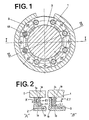
- FIG. 1 shows a cylinder 1 with a coaxially arranged piston 2.
- a number of clamping bodies 3 is arranged in a circumferential groove 2.1 between the piston 2 and the inner wall of the cylinder 1.
- the clamping body 3 is shown in the left figure “A” in its clamping position and in the right figure “B” in its free-running position.
- Each clamping body 3 is shaped so that its height along the line aa for the clamping position is greater than its height along the line bb for the freewheeling position.
- Two rings of clamping bodies 3 are therefore to be provided, one of which is used to fix the piston 2 in one of the two directions of movement, see FIG. 3.
- the piston 2 located in the cylinder 1 is shown in FIG.
- Two control valves 5a, 5b shown in FIG. 3 are actually located in piston 2, but are shown outside the piston for a better overview.
- One control valve 5a, 5b is assigned to one of the two rings of sprags 3.
- the lines 7a, 7b, 8a, 8b, 9b, 10b, 11, 12 shown in dashed lines are to be understood as bores in the piston 2.
- 6 with a servo valve is designated, which is essentially a 4/3-way valve, which has four line connections and three switching positions having.
- the servo valve 6 is connected to a pressure source 6.2 via a line 6.1.
- the control valves 5a, 5b are both of exactly the same design and control the actuation of the clamping bodies 3 in the desired manner, as will be explained below.
- the control valves 5a, 5b have a main piston 13 to which a smaller control piston 13.1 is assigned.
- a compression spring 13.3 is inserted, which wants to separate the two pistons 13, 13.1 from each other.
- On the opposite side of the main piston 13 there is a ventilation line 5.3, from which a branch line 5.4 branches off to the control piston 13.1.
- the pneumatic linear actuator described works as follows:
- the servo valve 6 is switched so that the line 7a is pressurized with compressed air.
- the compressed air passes through the pressure valve 5.1 to the underside of the main piston 13, which is pressed upward against the force of a compression spring 13.3.
- the compressed air is fed via line 7b into the back of a pressure ring 14.
- the pressure ring 14 is located in the circumferential groove 2.1 of the piston 2 and is in contact with the clamping bodies 3 of the right clamping body ring.
- the pressure ring 14 is axially displaceable in the circumferential groove 2.1.
- the pressure ring 14 Due to the compressed air arriving through line 7b, the pressure ring 14 is displaced in the direction of the clamping body 3, as a result of which it is tilted from its clamping position into the freewheeling position.
- the clamping body 3 has a corresponding shape that the Pressure ring 14 engages the foot 3.1 of the clamp body 3 and thus initiates the tilting movement.
- the compressed air supply is interrupted by means of the servo valve 6, whereupon the pressure ring 14 is immediately moved back to its original position by the force of compression springs 18, see FIG. 4.
- the compression springs 18 are guided in longitudinal bores 18.1 in piston 2.
- the clamping bodies 3 assigned to the pressure ring 14 immediately tilt into their locking position, supported by compression springs 20, and hold the piston 2 firmly.
- the air still in the back of the pressure ring 14 can escape to the outside through the lines 7b, 11, via control pistons 13.1 and line 5.4 via the vent line 5.3.
- the compression springs 18 acting on the pressure ring 14 are supported on a second, similar pressure ring 19, which is assigned to a second ring of clamping bodies 3 and ensures that the piston 2 is locked in the opposite direction. If the servo valve 6 is brought into the middle position, in which neither compressed air supply nor compressed air discharge takes place, the two pressure rings 14, 19 are pressed apart from one another by the compression springs 18, as a result of which both wreaths of clamping bodies 3 are in their clamping position. The compressed air located on the rear of the pistons 14, 19 is conducted to the outside via the lines 7b, 11, 5.4 or line 8b, 12, 5.4 and via the vent line 5.3.
- the springs 20 assigned to the clamping body 3 ensure that the clamping bodies 3 always remain in slight contact with the inner wall of the cylinder 1 even in their freewheeling position. This results in an immediate clamping effect when the pressure ring 14 or 19 retreats and thus a quick reaction to the control command to lock the piston 2, thereby ensuring a high positioning accuracy of the linear drive described.
- the design of the locking system described above is suitable for pneumatic cylinders with piston rod as well as for rodless pneumatic cylinders.
- a carriage which is movable in the longitudinal direction on the outer wall of the cylinder 1 is provided and is connected to the piston 2 by means of a longitudinal slot in the cylinder 1 provided with corresponding seals.
- the clamping bodies 3 instead of being arranged on the piston 2 at the outlet opening of the piston rod from the cylinder 1, as in the exemplary embodiment, and clamp the piston rod in its locking position and thus lock the piston 2.
- the clamping bodies 3 can be arranged on the outer slide, where in their locking position they clamp the slide on the outer wall of the cylinder, as a result of which the piston 2 is also locked via the slide.
- clamping bodies 3 instead of the seven clamping bodies 3 arranged in FIG. 1 for each clamping body ring, a different number of clamping bodies 3 can also be provided.
- Both the inner wall of the cylinder 1 and the clamping body 3 are suitably made of hardened steel.
- the filtered, oiled compressed air that is usually provided for compressed air networks is suitable as compressed air.
Landscapes
- Engineering & Computer Science (AREA)
- Physics & Mathematics (AREA)
- Fluid Mechanics (AREA)
- Mechanical Engineering (AREA)
- General Engineering & Computer Science (AREA)
- Actuator (AREA)
- Vibration Prevention Devices (AREA)
- Apparatuses For Generation Of Mechanical Vibrations (AREA)
- Fuel-Injection Apparatus (AREA)
- Braking Systems And Boosters (AREA)
- Hydraulic Clutches, Magnetic Clutches, Fluid Clutches, And Fluid Joints (AREA)
- Manipulator (AREA)
- Jigs For Machine Tools (AREA)
Description
- Die Erfindung bezieht sich auf einen pneumatische Linearantrieb mit einer einen Zylinder sowie einen darin angeordneten Kolben umfassenden Kolben/Zylinder-Einheit, bei welcher durch eine entsprechende Druckmittel-Beaufschlagung der Kolben in die eine oder andere Richtung axial verschiebbar und mittels kippbarer Klemmkörper, welche mit einem mit entsprechendem Druckmittel beaufschlagten Druckring in Wirkverbindung stehen, in beliebiger Stellung arretierbar sind.
- Pneumatische Linearantriebe sind in verschiedenen Ausführungen bekannt und dienen im wesentlichen als Antriebs-, Führungs- und/oder Positioniervorrichtungen, deren Einsatzmöglichkeit jedoch in hohem Masse von der jeweiligen Positionier-Geschwindigkeit und der Positionier-Genauigkeit abhängig ist. Bei diesen bekannten Linearantrieben ist es von Nachteil, dass unter Berücksichtigung des nicht exakt arbeitenden Systems von Druck und Gegendruck, das Anfahren einer gewünschten Position nur innerhalb einer relativ grossen Toleranz möglich ist.
- Aus der AT-A 328 327 ist eine pneumatische Stellvorrichtung bekannt, welche im wesentlichen einen in einem Zylinder angeordneten Kolben mit daran angeordneter Kolbenstange sowie einen mit entsprechend angeordneten Kanälen versehenen Zylinderkopf umfasst, in welchem zwei in axialer Richtung an der Kolbenstange im Abstand zueinander angeordnete und entsprechend mit Druckluft beaufschlagbare Kolben vorgesehen sind. In entsprechend ausgebildeten Ausnehmungen des Zylinderkopfes sind weiterhin zwei mit den beiden Kolben wirkverbundene Sperrhebel gegen die Rückstellkraft einer Druckfeder schwenkbar gelagert, wobei die Sperrhebel mit ihren entsprechend ausgebildeten Stirnflächen je nach Druckluft-Beaufschlagung mit der Kolbenstange in Eingriff oder ausser Eingriff bringbar sind. Mittels dieser zum Öffnen und Schliessen von Abdeckelementen oder dergleichen ausgebildeten Stellvorrichtung kann einerseits eine in die eine oder andere Richtung orientierte Bewegung der Kolbenstange und andererseits durch die Klemmwirkung der Sperrhebel eine Arretierung der Kolbenstange erreicht werden.
- Aus der FR-A 2 410 158 ist eine Kolben/Zylindereinheit bekannt, welche im wesentlichen eine Kolbenstange, ein Zylindergehäuse sowie einen daran angeordneten Zylinderkopf umfasst, in welchem mindestens ein als Kreisringscheibe ausgebildetes Klemmelement angeordnet ist, welches von einem Aggregat mit Druckmittel beaufschlagt gegen die Rückstellkraft einer Druckfeder kippbar mit der Kolbenstange in Eingriff bringbar ist und dadurch eine Arretierung der Kolbenstange bewirkt.
- Der Erfindung liegt die Aufgabe zugrunde, eine Kolben/Zylinder-Einheit für einen pneumatischen Linearantrieb dahingehend zu verbessern, dass unter Beibehaltung einer entsprechend optimalen Dimensionierung und Leistungsfähigkeit die beiden relativ zueinander bewegbaren Teile der Kolben/Zylinder-Einheit in beliebiger Position fixierbar sind.
- Diese Aufgabe wird erfindungsgemäss durch gelöst, dass
- ― die Klemmkörper mit dem zugeordneten Druckring in einer Umfangsnut eines der beiden relativ zueinander bewegbaren Teile der Kolben/Zylinder-Einheit angeordnet sind, und
- ― der einzelne Klemmkörper auf der dem Druckring zugewandten Seite mit einem Vorsprung und auf der dem Druckring abgewandten Seite mit einer in Umfangsrichtung verlaufenden, an der zugeordneten Begrenzungswand der Umfangsnut anliegenden und als giebelförmiger Kipp-Punkt ausgebildeten Erhebung versehen ist, und
- ― der einzelne Klemmkörper durch die Rückstellkraft einer zwischen dem Druckring und dem Klemmkörper in radialer Richtung oberhalb des Kipp-Punktes angeordneten Druckfeder in eine den bewegten Teil der Kolben/Zylinder-Einheit klemmende Stellung und bei entsprechender Beaufschlagung des mit dem in radialer Richtung unterhalb des Kipp-Punktes angeordneten Vorsprung wirkverbundenen Druckringes in eine den bewegten Teil der Kolben/Zylinder-Einheit freigebende Stellung kippbar ist.
- Weitere Merkmale der Erfindung ergeben sich aus der folgenden Beschreibung in Verbindung mit der Zeichnung und den Patentansprüchen.
- Die Erfindung wird nachstehend anhand der Zeichnung beschrieben. Es zeigt:
- Fig. 1
- eine in Schnittansicht dargestellte Kolben/Zylinder-Einheit für einen pneumatischen Linearantrieb,
- Fig. 2
- einen Teilschnitt der Zylinder-Kolben-Einheit mit der Darstellung eines Klemmkörpers in der Klemmstellung und in der Freilaufstellung,
- Fig. 3
- einen Längsschnitt der Zylinder-Kolben-Einheit nach Fig. 1 längs der Linie I-I in Figur 1 und
- Fig. 4
- einen Längsschnitt der Zylinder-Kolben-Einheit nach Fig. 1 längs der Linie II-II in Figur 1.
- Aus Figur 1 ist ein Zylinder 1 mit einem koaxial angeordneten Kolben 2 ersichtlich. Zwischen dem Kolben 2 und der Innenwand des Zylinders 1 ist in einer Umfangsnut 2.1 eine Anzahl von Klemmkörpern 3 angeordnet. In Figur 2 ist der Klemmkörper 3 in der linken Figur "A" in seiner Klemmstellung und in der rechten Figur "B" in seiner Freilaufstellung dargestellt. Jeder Klemmkörper 3 ist so geformt, dass seine Höhe längs der Linie a-a für die Klemmstellung grösser ist als seine Höhe längs der Linie b-b für die Freilaufstellung. Durch Kippen der Klemmkörper 3 kann die Innenwand des Zylinders 1 mit dem Kolben 2 gegenseitig fixiert werden, sodass eine Längsbewegung des Kolbens 2 in einer der beiden Hubrichtungen unmöglich ist, ohne dass der Kolben 2 vom Zylinder 1 freigegeben wird. Es sind deshalb zwei Kränze von Klemmkörpern 3 vorzusehen, von denen je einer zum Fixieren des Kolbens 2 in einer der beiden Bewegungsrichtungen dient, siehe Figur 3. In Figure 3 ist der im Zylinder 1 befindliche Kolben 2 dargestellt. Zwei in Figur 3 dargestellte Steuerventile 5a, 5b befinden sich in Wirklichkeit in Kolben 2, sind aber zur besseren Uebersicht ausserhalb des Kolbens dargestellt. Je ein Steuerventil 5a, 5b ist einem der beiden Kränze von Klemmkörpern 3 zugeordnet. Die gestrichelt dargestellten Leitungen 7a, 7b, 8a, 8b, 9b, 10b, 11, 12 sind als Bohrungen im Kolben 2 zu verstehen. Mit 6 ist ein Servoventil bezeichnet, welches im wesentlichen ein 4/3-Wegventil ist, welches über vier Leitungsanschlüsse und drei Schaltstellungen aufweist. Das Servoventil 6 ist über eine Leitung 6.1 mit einer Druckquelle 6.2 verbunden.
- Die Steuerventile 5a, 5b sind beide genau gleich ausgebildet und steuern die Betätigung der Klemmkörper 3 in der gewünschten Weise, wie dies noch erläutert wird. Die Steuerventile 5a, 5b weisen einen Hauptkolben 13 auf, dem ein kleinerer Steuerkolben 13.1 zugeordnet ist. In einem Innenraum 13.2 des Hauptkolbens 13 und des Steuerkolbens 13.1 ist eine Druckfeder 13.3 eingelegt, welche die beiden Kolben 13, 13.1 von einander trennen will. Auf der dem Steuerkolben 13.1 gegenüber liegenden Seite des Hauptkolbens 13 ist ein federbelastetes Druckventil 5.1 angeordnet, an dem die Leitungen 7a, 9b bzw. 8a, 10b münden und das über einen Durchgang 5.2 mit der einen Stirnseite des Hauptkolbens 13 in Verbindung steht. An der gegenüberliegenden Seite des Hauptkolbens 13 ist eine Entlüftungsleitung 5.3 angeordnet, von der eine Zweigleitung 5.4 zum Steuerkolben 13.1 abzweigt.
- Der beschriebene pneumatische Linearantrieb arbeitet wie folgt:
- Soll der Kolben 2 beispielsweise nach rechts bewegt werden, wird das Servoventil 6 so geschaltet, dass die Leitung 7a mit Druckluft beaufschlagt wird. Die Druckluft gelangt über das Druckventil 5.1 auf die Unterseite des Hauptkolbens 13, der entgegen der Kraft einer Druckfeder 13.3 nach oben gedrückt wird. Dort wird die Druckluft über die Leitung 7b in den Rücken eines Druckringes 14 geführt. Der Druckring 14 befindet sich in der Umfangsnut 2.1 des Kolbens 2 und steht in Berührung mit den Klemmkörpern 3 des rechten Klemmkörperkranzes. Der Druckring 14 ist in der Umfangsnut 2.1 axial verschiebbar angeordnet. Durch die durch Leitung 7b ankommende Druckluft wird der Druckring 14 in Richtung des Klemmkörpers 3 verschoben, wodurch diese von ihrer Klemmstellung in die Freilaufstellung gekippt werden. Der Klemmkörper 3 weist eine entsprechende Formgebung auf, dass der Druckring 14 am Fuss 3.1 des Klemmkörpers 3 angreift und so die Kippbewegung einleitet.
- Durch das Verschieben des Druckringes 14 wird gleichzeitig der Anschluss der Leitung 7c frei, wodurch die Druckluft ihren Weg bis zum linken Druckraum 15 des Zylinders 1 fortsetzen kann, welchen sie über ein Druckventil 16 erreicht. Durch den im Druckraum 15 des Zylinders 1 ansteigenden Druck wird der Kolben 2 nach rechts gedrückt. Dies erfolgt ungehindert, da die dem Druckring 14 zugeordneten Klemmkörper 3 in ihrer Freilaufstellung sind. Die im rechten Druckraum 17 des Zylinders 1 befindliche Luft kann durch die Leitung 10a, Druckventil 17.1, Leitung 10b, Druckventil 5.1 und Leitung 8a, siehe Figur 4, dem Servoventil 6 zugeführt und von dort dem Druckluft-System zurückgeführt werden.
- Ist die gewünschte Position des Kolbens 2 im Zylinder 1 erreicht, wird mittels des Servoventils 6 die Druckluftzufuhr unterbrochen, worauf sich der Druckring 14 sofort durch die Kraft von Druckfedern 18, siehe Figur 4, in seine ursprüngliche Stellung zurückverschiebt. Die Druckfedern 18 sind in Längsbohrungen 18.1 in Kolben 2 geführt. Die den Druckring 14 zugeordneten Klemmkörper 3 kippen dabei, unterstützt durch Druckfedern 20, augenblicklich in ihre Sperrstellung und halten den Kolben 2 fest. Die im Rücken des Druckringes 14 noch befindliche Luft kann durch die Leitungen 7b, 11, über Steuerkolben 13.1 und Leitung 5.4 über die Entlüftungsleitung 5.3 nach aussen entweichen.
- Die auf den Druckring 14 wirkenden Druckfedern 18 stützen sich an einen zweiten, gleichartigen Druckring 19 ab, welcher einem zweiten Kranz von Klemmkörpern 3 zugeordnet ist und für die Arretierung des Kolbens 2 in der Gegenrichtung sorgt. Wird das Servoventil 6 in die mittlere Stellung gebracht, in welcher weder Druckluftzufuhr noch Druckluftableitung erfolgt, werden die beiden Druckringe 14, 19 durch die Druckfedern 18 voneinander weggedrückt, wodurch sich beide Kränze von Klemmkörpern 3 in ihrer Klemmstellung befinden. Die auf der Rückseite der Kolben 14, 19 befindliche Druckluft wird über die Leitungen 7b, 11, 5.4 bzw. Leitung 8b, 12, 5.4 und über die Entlüftungsleitung 5.3 nach aussen geleitet.
- Die dem Klemmkörper 3 zugeordneten Federn 20 bewirken, dass die Klemmkörper 3 selbst in ihrer Freilaufstellung stets in leichtem Kontakt mit der Innenwand des Zylinders 1 bleiben. Hierdurch ergibt sich beim Zurückweichen des Druckringes 14 bzw. 19 eine sofortige Klemmwirkung und damit eine rasche Reaktion auf den Steuerbefehl, den Kolben 2 zu arretieren, wodurch eine hohe Positioniergenauigkeit des beschriebenen Linearantriebes gewährleistet wird.
- Mittels der dritten Schaltstellung des Servoventils 6 wird der Kolben 2 in gleicher Weise, wie dies vorstehend beschrieben wurde, nach links geschoben werden. Hierbei wird Druckluft über die Leitung 8a, Druckventil 5.1 des Steuerventils 5b und Leitung 8b auf die Rückseite des Druckringes 19 geführt, der die ihm zugeordneten Klemmkörper 3 in die Freilaufstellung drückt, worauf Druckluft über die Druckleitung 8c und Druckventil 16 in den Druckraum 17 geleitet wird, durch welche der Kolben 2 nach links verschoben wird. Die im linken Druckraum 15 des Zylinders 2 befindliche Luft kann dabei über die Leitungen 9a, 9b, 7a und das Servoventil 6 abgeleitet werden, siehe Figur 4.
- Die vorstehend beschriebene Ausführung des Arretier-Systems ist sowohl für Pneumatikzylinder mit Kolbenstange als auch für kolbenstangenlose Pneumatikzylinder geeignet. Im letztgenannten Fall ist ein in Längsrichtung an der Aussenwand des Zylinders 1 verfahrbarer Schlitten vorgesehen, welcher durch einen mit entsprechenden Abdichtungen versehenen Längsschlitz im Zylinder 1 mit dem Kolben 2 in Verbindung steht. Bei einem Linearantrieb mit einem Pleumatikzylinder mit Kolbenstange können die Klemmkörper 3 anstatt wie im Ausführungsbeispiel am Kolben 2 an der Austrittsöffnung der Kolbenstange aus dem Zylinder 1 angeordnet sein und dort in ihrer Arretierstellung die Kolbenstange festklemmen und damit den Kolben 2 arretieren.
- Bei einem Linearantrieb mit einem kolbenstangenlosen Kolben können die Klemmkörper 3 am aussenliegenden Schlitten angeordnet sein, wo sie in ihrer Arretierstellung den Schlitten an der Zylinderaussenwand festklemmen, wodurch über den Schlitten auch der Kolben 2 arretiert wird.
- Statt der in Figur 1 angeordneten sieben Klemmkörper 3 für jeden Klemmkörperkranz kann auch eine andere Zahl von Klemmkörpern 3 vorgesehen werden.
- Sowohl die Innenwand des Zylinders 1 als auch die Klemmkörper 3 bestehen zweckmässig aus gehärtetem Stahl. Als Druckluft eignet sich die üblicherweise für Druckluftnetze zur Verfügung gestellte gefilterte, geölte Druckluft.
Claims (6)
Priority Applications (1)
| Application Number | Priority Date | Filing Date | Title |
|---|---|---|---|
| AT88114921T ATE65586T1 (de) | 1987-09-17 | 1988-09-13 | Pneumatischer linearantrieb mit einer zylinderkolben-einheit. |
Applications Claiming Priority (2)
| Application Number | Priority Date | Filing Date | Title |
|---|---|---|---|
| CH3596/87A CH673320A5 (de) | 1987-09-17 | 1987-09-17 | |
| CH3596/87 | 1987-09-17 |
Publications (2)
| Publication Number | Publication Date |
|---|---|
| EP0309803A1 EP0309803A1 (de) | 1989-04-05 |
| EP0309803B1 true EP0309803B1 (de) | 1991-07-24 |
Family
ID=4259397
Family Applications (1)
| Application Number | Title | Priority Date | Filing Date |
|---|---|---|---|
| EP88114921A Expired - Lifetime EP0309803B1 (de) | 1987-09-17 | 1988-09-13 | Pneumatischer Linearantrieb mit einer Zylinder-Kolben-Einheit |
Country Status (5)
| Country | Link |
|---|---|
| EP (1) | EP0309803B1 (de) |
| AT (1) | ATE65586T1 (de) |
| CH (1) | CH673320A5 (de) |
| DE (1) | DE3863882D1 (de) |
| ES (1) | ES2022968B3 (de) |
Families Citing this family (1)
| Publication number | Priority date | Publication date | Assignee | Title |
|---|---|---|---|---|
| DE29809717U1 (de) * | 1998-05-29 | 1998-08-20 | Bümach Engineering International B.V., Emmen | Endlagenverriegelung hydraulischer Arbeitszylinder |
Family Cites Families (4)
| Publication number | Priority date | Publication date | Assignee | Title |
|---|---|---|---|---|
| GB1188100A (en) * | 1967-10-07 | 1970-04-15 | Dinglerwerke Aktiengesellschft | Fluid Operated Motors |
| AT328327B (de) * | 1974-04-10 | 1976-03-10 | Wabco Westinghouse Gmbh | Pneumatische stellvorrichtung |
| US4214795A (en) * | 1977-11-25 | 1980-07-29 | Shoketsu Kinzoku Kogyo Kabushiki Kaisha | Piston braking device for hydraulic or pneumatic cylinders |
| DE3504269A1 (de) * | 1985-02-08 | 1986-08-21 | ORIGA GmbH Pneumatik, 7024 Filderstadt | Druckmittelzylinder |
-
1987
- 1987-09-17 CH CH3596/87A patent/CH673320A5/de not_active IP Right Cessation
-
1988
- 1988-09-13 EP EP88114921A patent/EP0309803B1/de not_active Expired - Lifetime
- 1988-09-13 DE DE8888114921T patent/DE3863882D1/de not_active Expired - Lifetime
- 1988-09-13 ES ES88114921T patent/ES2022968B3/es not_active Expired - Lifetime
- 1988-09-13 AT AT88114921T patent/ATE65586T1/de not_active IP Right Cessation
Also Published As
| Publication number | Publication date |
|---|---|
| EP0309803A1 (de) | 1989-04-05 |
| ATE65586T1 (de) | 1991-08-15 |
| ES2022968B3 (es) | 1991-12-16 |
| DE3863882D1 (de) | 1991-08-29 |
| CH673320A5 (de) | 1990-02-28 |
Similar Documents
| Publication | Publication Date | Title |
|---|---|---|
| EP0326639B1 (de) | Steuerventileinrichtung an einem mit Druckluft betriebenen Gerät zum Eintreiben von Befestigungsmitteln | |
| EP1266775B1 (de) | Pneumatisches Schaltventil für Anlagen zum Heben und Senken des Fahrzeugaufbaus von luftgefederten Fahrzeugen | |
| EP1357298B1 (de) | Betätigungsventil für einen zweiseitig wirksamen Pneumatikzylinder | |
| EP0418507B2 (de) | Brems- oder/und Klemmeinrichtung | |
| DE3808542C2 (de) | Ventiltrieb für ein Gaswechselventil einer Brennkraftmaschine | |
| EP0937206B1 (de) | Pneumatischer oder hydraulischer stellmotor mit einer abschalteinrichtung | |
| EP0465955B1 (de) | Pneumatisch betätigbarer Linearantrieb für Punktschweiss-Automaten | |
| DE2845266C2 (de) | Sicherheitsfeststellbremse für hydraulische Aufzüge, Hebebühnen u.dgl. | |
| DE2705914A1 (de) | Umsteuerventil | |
| DE1963266U (de) | Druckmittel beaufschlagte betaetigungsvorrichtung, insbesondere fuer zahnradgetriebe. | |
| DE3542069A1 (de) | Kolben-zylinder-anordnung als antrieb fuer eine schweisselektrode | |
| EP0363575B1 (de) | Druckluftzylinder mit Endlageverriegelung, insbesondere zur Betätigung von Rauchabzugsklappen | |
| DE1917368B2 (de) | Mit Druckluft arbeitende Hilfs kraft Schaltvorrichtung fur synchronisierte Wechselgetriebe von Kraftfahrzeugen | |
| DE29610911U1 (de) | Mehrstufige fluidbetätigte Arbeitszylinderanordnung | |
| EP0568858B1 (de) | Durch Steuerdruck verriegelbare Kolbenbetätigung, insbesondere für den Transport eines Überrollbügels bei Kraftfahrzeugen | |
| DE102004046976B4 (de) | Mehrwegeventil | |
| DE3632355A1 (de) | Druckmittelbetaetigter vielstellungszylinder | |
| DE3607063C2 (de) | ||
| DE19903511A1 (de) | Stellmotor mit einer Abschalteinrichtung | |
| DE2245017A1 (de) | Vor- und fernsteuerbares hydraulisches, selbsttaetig steuerndes wegeventil, das auch fuer gasfoermige medien geeignet ist | |
| DE1239578B (de) | Bctaetigungsvorrichtung fuer eine Bremse, insbesondere Kraftfahrzeugbremse | |
| DE2033614A1 (de) | Betatigungsghed fur Steuerventile | |
| DE1270906B (de) | Steuerschieber | |
| EP0309803A1 (de) | Pneumatischer Linearantrieb mit einer Zylinder-Kolben-Einheit | |
| DE4012968A1 (de) | Pneumatisch betaetigbarer linearantrieb fuer punktschweiss-automaten |
Legal Events
| Date | Code | Title | Description |
|---|---|---|---|
| PUAI | Public reference made under article 153(3) epc to a published international application that has entered the european phase |
Free format text: ORIGINAL CODE: 0009012 |
|
| AK | Designated contracting states |
Kind code of ref document: A1 Designated state(s): AT DE ES FR GB IT NL SE |
|
| 17P | Request for examination filed |
Effective date: 19890909 |
|
| 17Q | First examination report despatched |
Effective date: 19900110 |
|
| GRAA | (expected) grant |
Free format text: ORIGINAL CODE: 0009210 |
|
| AK | Designated contracting states |
Kind code of ref document: B1 Designated state(s): AT DE ES FR GB IT NL SE |
|
| REF | Corresponds to: |
Ref document number: 65586 Country of ref document: AT Date of ref document: 19910815 Kind code of ref document: T |
|
| ITF | It: translation for a ep patent filed | ||
| GBT | Gb: translation of ep patent filed (gb section 77(6)(a)/1977) | ||
| REF | Corresponds to: |
Ref document number: 3863882 Country of ref document: DE Date of ref document: 19910829 |
|
| ET | Fr: translation filed | ||
| PLBE | No opposition filed within time limit |
Free format text: ORIGINAL CODE: 0009261 |
|
| STAA | Information on the status of an ep patent application or granted ep patent |
Free format text: STATUS: NO OPPOSITION FILED WITHIN TIME LIMIT |
|
| 26N | No opposition filed | ||
| PGFP | Annual fee paid to national office [announced via postgrant information from national office to epo] |
Ref country code: GB Payment date: 19920908 Year of fee payment: 5 |
|
| PGFP | Annual fee paid to national office [announced via postgrant information from national office to epo] |
Ref country code: SE Payment date: 19920914 Year of fee payment: 5 |
|
| PGFP | Annual fee paid to national office [announced via postgrant information from national office to epo] |
Ref country code: AT Payment date: 19920929 Year of fee payment: 5 |
|
| PGFP | Annual fee paid to national office [announced via postgrant information from national office to epo] |
Ref country code: NL Payment date: 19920930 Year of fee payment: 5 Ref country code: ES Payment date: 19920930 Year of fee payment: 5 |
|
| PGFP | Annual fee paid to national office [announced via postgrant information from national office to epo] |
Ref country code: FR Payment date: 19921005 Year of fee payment: 5 |
|
| REG | Reference to a national code |
Ref country code: FR Ref legal event code: ST |
|
| PG25 | Lapsed in a contracting state [announced via postgrant information from national office to epo] |
Ref country code: GB Effective date: 19930913 Ref country code: AT Effective date: 19930913 |
|
| PG25 | Lapsed in a contracting state [announced via postgrant information from national office to epo] |
Ref country code: SE Effective date: 19930914 Ref country code: ES Free format text: LAPSE BECAUSE OF EXPIRATION OF PROTECTION Effective date: 19930914 |
|
| PGFP | Annual fee paid to national office [announced via postgrant information from national office to epo] |
Ref country code: DE Payment date: 19931011 Year of fee payment: 6 |
|
| REG | Reference to a national code |
Ref country code: FR Ref legal event code: D1 |
|
| PG25 | Lapsed in a contracting state [announced via postgrant information from national office to epo] |
Ref country code: NL Effective date: 19940401 |
|
| GBPC | Gb: european patent ceased through non-payment of renewal fee |
Effective date: 19930913 |
|
| NLV4 | Nl: lapsed or anulled due to non-payment of the annual fee | ||
| PG25 | Lapsed in a contracting state [announced via postgrant information from national office to epo] |
Ref country code: FR Free format text: LAPSE BECAUSE OF NON-PAYMENT OF DUE FEES Effective date: 19940531 |
|
| REG | Reference to a national code |
Ref country code: FR Ref legal event code: ST |
|
| EUG | Se: european patent has lapsed |
Ref document number: 88114921.5 Effective date: 19940410 |
|
| PG25 | Lapsed in a contracting state [announced via postgrant information from national office to epo] |
Ref country code: DE Effective date: 19950601 |
|
| REG | Reference to a national code |
Ref country code: ES Ref legal event code: FD2A Effective date: 19990601 |
|
| PG25 | Lapsed in a contracting state [announced via postgrant information from national office to epo] |
Ref country code: IT Free format text: LAPSE BECAUSE OF NON-PAYMENT OF DUE FEES;WARNING: LAPSES OF ITALIAN PATENTS WITH EFFECTIVE DATE BEFORE 2007 MAY HAVE OCCURRED AT ANY TIME BEFORE 2007. THE CORRECT EFFECTIVE DATE MAY BE DIFFERENT FROM THE ONE RECORDED. Effective date: 20050913 |