EP0308593A1 - Verfahren und Vorrichtung zur Verbindung von Gegenständen aus Nichtoxidkeramik mittels Mikrowellen - Google Patents
Verfahren und Vorrichtung zur Verbindung von Gegenständen aus Nichtoxidkeramik mittels Mikrowellen Download PDFInfo
- Publication number
- EP0308593A1 EP0308593A1 EP88110766A EP88110766A EP0308593A1 EP 0308593 A1 EP0308593 A1 EP 0308593A1 EP 88110766 A EP88110766 A EP 88110766A EP 88110766 A EP88110766 A EP 88110766A EP 0308593 A1 EP0308593 A1 EP 0308593A1
- Authority
- EP
- European Patent Office
- Prior art keywords
- items
- joint
- monitoring
- iris
- acoustic
- Prior art date
- Legal status (The legal status is an assumption and is not a legal conclusion. Google has not performed a legal analysis and makes no representation as to the accuracy of the status listed.)
- Granted
Links
Images


Classifications
-
- H—ELECTRICITY
- H05—ELECTRIC TECHNIQUES NOT OTHERWISE PROVIDED FOR
- H05B—ELECTRIC HEATING; ELECTRIC LIGHT SOURCES NOT OTHERWISE PROVIDED FOR; CIRCUIT ARRANGEMENTS FOR ELECTRIC LIGHT SOURCES, IN GENERAL
- H05B6/00—Heating by electric, magnetic or electromagnetic fields
- H05B6/64—Heating using microwaves
- H05B6/66—Circuits
- H05B6/68—Circuits for monitoring or control
-
- C—CHEMISTRY; METALLURGY
- C04—CEMENTS; CONCRETE; ARTIFICIAL STONE; CERAMICS; REFRACTORIES
- C04B—LIME, MAGNESIA; SLAG; CEMENTS; COMPOSITIONS THEREOF, e.g. MORTARS, CONCRETE OR LIKE BUILDING MATERIALS; ARTIFICIAL STONE; CERAMICS; REFRACTORIES; TREATMENT OF NATURAL STONE
- C04B35/00—Shaped ceramic products characterised by their composition; Ceramics compositions; Processing powders of inorganic compounds preparatory to the manufacturing of ceramic products
- C04B35/622—Forming processes; Processing powders of inorganic compounds preparatory to the manufacturing of ceramic products
- C04B35/64—Burning or sintering processes
- C04B35/645—Pressure sintering
-
- C—CHEMISTRY; METALLURGY
- C04—CEMENTS; CONCRETE; ARTIFICIAL STONE; CERAMICS; REFRACTORIES
- C04B—LIME, MAGNESIA; SLAG; CEMENTS; COMPOSITIONS THEREOF, e.g. MORTARS, CONCRETE OR LIKE BUILDING MATERIALS; ARTIFICIAL STONE; CERAMICS; REFRACTORIES; TREATMENT OF NATURAL STONE
- C04B37/00—Joining burned ceramic articles with other burned ceramic articles or other articles by heating
- C04B37/001—Joining burned ceramic articles with other burned ceramic articles or other articles by heating directly with other burned ceramic articles
-
- C—CHEMISTRY; METALLURGY
- C04—CEMENTS; CONCRETE; ARTIFICIAL STONE; CERAMICS; REFRACTORIES
- C04B—LIME, MAGNESIA; SLAG; CEMENTS; COMPOSITIONS THEREOF, e.g. MORTARS, CONCRETE OR LIKE BUILDING MATERIALS; ARTIFICIAL STONE; CERAMICS; REFRACTORIES; TREATMENT OF NATURAL STONE
- C04B37/00—Joining burned ceramic articles with other burned ceramic articles or other articles by heating
- C04B37/02—Joining burned ceramic articles with other burned ceramic articles or other articles by heating with metallic articles
- C04B37/021—Joining burned ceramic articles with other burned ceramic articles or other articles by heating with metallic articles in a direct manner, e.g. direct copper bonding [DCB]
-
- H—ELECTRICITY
- H05—ELECTRIC TECHNIQUES NOT OTHERWISE PROVIDED FOR
- H05B—ELECTRIC HEATING; ELECTRIC LIGHT SOURCES NOT OTHERWISE PROVIDED FOR; CIRCUIT ARRANGEMENTS FOR ELECTRIC LIGHT SOURCES, IN GENERAL
- H05B6/00—Heating by electric, magnetic or electromagnetic fields
- H05B6/64—Heating using microwaves
- H05B6/80—Apparatus for specific applications
-
- C—CHEMISTRY; METALLURGY
- C04—CEMENTS; CONCRETE; ARTIFICIAL STONE; CERAMICS; REFRACTORIES
- C04B—LIME, MAGNESIA; SLAG; CEMENTS; COMPOSITIONS THEREOF, e.g. MORTARS, CONCRETE OR LIKE BUILDING MATERIALS; ARTIFICIAL STONE; CERAMICS; REFRACTORIES; TREATMENT OF NATURAL STONE
- C04B2235/00—Aspects relating to ceramic starting mixtures or sintered ceramic products
- C04B2235/65—Aspects relating to heat treatments of ceramic bodies such as green ceramics or pre-sintered ceramics, e.g. burning, sintering or melting processes
- C04B2235/656—Aspects relating to heat treatments of ceramic bodies such as green ceramics or pre-sintered ceramics, e.g. burning, sintering or melting processes characterised by specific heating conditions during heat treatment
- C04B2235/6562—Heating rate
-
- C—CHEMISTRY; METALLURGY
- C04—CEMENTS; CONCRETE; ARTIFICIAL STONE; CERAMICS; REFRACTORIES
- C04B—LIME, MAGNESIA; SLAG; CEMENTS; COMPOSITIONS THEREOF, e.g. MORTARS, CONCRETE OR LIKE BUILDING MATERIALS; ARTIFICIAL STONE; CERAMICS; REFRACTORIES; TREATMENT OF NATURAL STONE
- C04B2235/00—Aspects relating to ceramic starting mixtures or sintered ceramic products
- C04B2235/65—Aspects relating to heat treatments of ceramic bodies such as green ceramics or pre-sintered ceramics, e.g. burning, sintering or melting processes
- C04B2235/656—Aspects relating to heat treatments of ceramic bodies such as green ceramics or pre-sintered ceramics, e.g. burning, sintering or melting processes characterised by specific heating conditions during heat treatment
- C04B2235/6567—Treatment time
-
- C—CHEMISTRY; METALLURGY
- C04—CEMENTS; CONCRETE; ARTIFICIAL STONE; CERAMICS; REFRACTORIES
- C04B—LIME, MAGNESIA; SLAG; CEMENTS; COMPOSITIONS THEREOF, e.g. MORTARS, CONCRETE OR LIKE BUILDING MATERIALS; ARTIFICIAL STONE; CERAMICS; REFRACTORIES; TREATMENT OF NATURAL STONE
- C04B2235/00—Aspects relating to ceramic starting mixtures or sintered ceramic products
- C04B2235/65—Aspects relating to heat treatments of ceramic bodies such as green ceramics or pre-sintered ceramics, e.g. burning, sintering or melting processes
- C04B2235/658—Atmosphere during thermal treatment
- C04B2235/6581—Total pressure below 1 atmosphere, e.g. vacuum
-
- C—CHEMISTRY; METALLURGY
- C04—CEMENTS; CONCRETE; ARTIFICIAL STONE; CERAMICS; REFRACTORIES
- C04B—LIME, MAGNESIA; SLAG; CEMENTS; COMPOSITIONS THEREOF, e.g. MORTARS, CONCRETE OR LIKE BUILDING MATERIALS; ARTIFICIAL STONE; CERAMICS; REFRACTORIES; TREATMENT OF NATURAL STONE
- C04B2235/00—Aspects relating to ceramic starting mixtures or sintered ceramic products
- C04B2235/65—Aspects relating to heat treatments of ceramic bodies such as green ceramics or pre-sintered ceramics, e.g. burning, sintering or melting processes
- C04B2235/66—Specific sintering techniques, e.g. centrifugal sintering
- C04B2235/667—Sintering using wave energy, e.g. microwave sintering
-
- C—CHEMISTRY; METALLURGY
- C04—CEMENTS; CONCRETE; ARTIFICIAL STONE; CERAMICS; REFRACTORIES
- C04B—LIME, MAGNESIA; SLAG; CEMENTS; COMPOSITIONS THEREOF, e.g. MORTARS, CONCRETE OR LIKE BUILDING MATERIALS; ARTIFICIAL STONE; CERAMICS; REFRACTORIES; TREATMENT OF NATURAL STONE
- C04B2237/00—Aspects relating to ceramic laminates or to joining of ceramic articles with other articles by heating
- C04B2237/30—Composition of layers of ceramic laminates or of ceramic or metallic articles to be joined by heating, e.g. Si substrates
- C04B2237/32—Ceramic
- C04B2237/36—Non-oxidic
- C04B2237/368—Silicon nitride
-
- Y—GENERAL TAGGING OF NEW TECHNOLOGICAL DEVELOPMENTS; GENERAL TAGGING OF CROSS-SECTIONAL TECHNOLOGIES SPANNING OVER SEVERAL SECTIONS OF THE IPC; TECHNICAL SUBJECTS COVERED BY FORMER USPC CROSS-REFERENCE ART COLLECTIONS [XRACs] AND DIGESTS
- Y02—TECHNOLOGIES OR APPLICATIONS FOR MITIGATION OR ADAPTATION AGAINST CLIMATE CHANGE
- Y02B—CLIMATE CHANGE MITIGATION TECHNOLOGIES RELATED TO BUILDINGS, e.g. HOUSING, HOUSE APPLIANCES OR RELATED END-USER APPLICATIONS
- Y02B40/00—Technologies aiming at improving the efficiency of home appliances, e.g. induction cooking or efficient technologies for refrigerators, freezers or dish washers
Definitions
- the invention relates to a method and apparatus for the microwave joining of two materials, particularly nonoxide ceramic items.
- the bonding together of ceramic materials is generally accomplished by many different methods and apparatuses. Exemplary methods and apparatuses are shown and described in U.S. Patent Nos. 4,384,909, 4,347,089, 3,998,632, 3,841,870, and 3,755,065.
- Prior art apparatuses for making joints between ceramic materials using microwave energy have sometimes employed ovens conventionally used for cooking food.
- the microwave field exists in many different orientations and power supplied to the oven is distributed accordingly. Not all of these orientations or modes couple efficiently to the ceramic items being joined.
- no methods and apparatuses in the prior art are known to simultaneously apply compressive forces to nonoxide ceramic items in either a vacuum or an atmosphere overpressurized with inert gas in order to stimulate and enhance the joining together of such items and to continuously monitor the joint being formed between the two nonoxide ceramic items in such vacuum or overpressurized atmosphere in order to assure a good bond.
- the primary object of the present invention is to use the more rapid and substantially uniform heating possible with microwave energy to join nonoxide ceramic materials in order to obtain improved strength and reliability as compared to materials bonded by conventional heating methods and apparatuses.
- Another object of the present invention is to provide at least two alternative methods for joining together nonoxide ceramic items by the application of microwave radiation under conditions where surface impurities, such as oxides and water vapor, on the nonoxide ceramic items may impede the joining process.
- One method required evacuation of a sealed chamber in which the nonoxide ceramic items are being joined while an alternative method provides for overpressurizing the sealed chamber surrounding the nonoxide ceramic items with an inert gas.
- microwave heating derive from the fact that heat is produced internally in the material being joined through dissipation of the electromagnetic energy absorbed by molecular dipoles in the material.
- microwave-heated specimens show a residual temperature gradient that is the reverse of the usual gradient observed with conventional heating methods. In other words, the center is hotter than the outer surface of microwave-heated specimens.
- microwave energy to heat materials has three distinct advantages: substantially uniform heating, more rapid heating, and a reverse temperature gradient. These advantages enchance the properties of microwave-treated ceramic materials in several ways.
- the substantial uniformity of heating tends to minimize the build-up of residual stresses, and, additionally, inhibits the diffusion of impurities throughout the material.
- the more rapid heating prevents grain growth and the weakening usually associated with the longer heating times of conventional thermal joining processes.
- the reversed thermal gradient enhances the outpassing of impurities from the center to the outer surface of the material and is a new mechanism for controlled constituent diffusion.
- the present invention has four additional advantages not found in the prior art methods and apparatuses for the microwave joining of nonoxide ceramic materials.
- First, the method is carried out in a vacuum of an enclosed atmosphere easily overpressurized by inert gas.
- a single mode microwave applicator is used so that the microwave field can be oriented to optimize the coupling of the radiation to the joint being formed, thereby increasing energy efficiency.
- Third, a compressive force is simultaneously applied to the nonoxide ceramic items being joined so that the microwave joining process is essentially completed in a much shorter time then in a conventional heat-joining process.
- Fourth, the joint being formed is continuously monitored by a nondestructive evaluator to assure that a good continuous bond is formed.
- each bond has sufficient structural integrity because it uses a nondestructive evaluator to constantly monitor each bond during its formation.
- the present invention is basically more efficient than the prior art convection and microwave ovens in which the entire mass of material inside the oven is heated. These conventional microwave ovens are energy-inefficient because mixed modes are used instead of only a single mode.
- Compressive forces are easily applied to the nonoxide ceramic items because only the region to be joined together is exposed to the microwave radiation while the rest of the ceramic material is outside of the single-mode microwave applicator. To the parts of the ceramic items outside of the applicator, a compressive force is applied, thereby speeding up the joining process.
- a nondestructive evaluator can be attached directly to the ceramic items. For example, in this way, acoustic reflections from the joint region can be monitored and the quality of the joint being formed can be continuously assessed.
- the joint or bond produced by the method and apparatus of the present invention is as strong as or stronger than the virgin nonoxide ceramic material.
- brazing material may be used and is not precluded from use by the present invention.
- FIG. 1 the apparatus for joining two nonoxide ceramic items together by applying microwave energy is shown.
- a magnetron 11 generates a microwave signal and delivers up to 1,000 watts of power at a frequency of about 2.45 gigahertz (GHz) in the direction of the arrow which represents a waveguide.
- GHz gigahertz
- a first calculator 12 directs the microwave energy in sequence along the path defined by the arrows and acts as a one way gate or insulator to protect the magnetron 11 against reflected microwaves. Any reflected microwaves are directed by this first circulator 12 to a first resistive load element 39 where they are dissipated.
- a voltage sampling probe 14 senses the magnitude of the propagating voltage of the microwave and extracts a very small fraction of it.
- a power heat 15 receives this samll part of the propagating voltage and provides an output voltage proportional to the square of the input voltage.
- a power meter 16 is used in conjunction with the power head 15 to provide an output display and voltage proportional to the forwarding propagating microwave voltage. This output then is fed into a noninverting input of a differential amplifier 22.
- the remaining part of the forward propagating voltage is transmitted to a second circulator 17 which acts as a microwave bridge element.
- This second circulator 17 has two functions represented by the double-headed arrow on the right-hand side thereof.
- the circulator 17 allows microwaves to pass in the forward direction to a sealed chamber 21.
- the circulator 17 redirects power reflected from the sealed chamber 21 to a voltage sampling probe 24, a power head 25, a power meter 26, and to an inverting input of the differential amplifier 22. Any excess reflected microwaves are directed by the second circulator 17 to a second resistive load element 40 where they are dissipated.
- the probe 24, power head 25, and power meter 26 are devices identical to the probe 14, power head 15, and power meter 16. However, the probe 24 senses the magnitude of the reflected voltage and the power meter 26 provides an output display and voltage proportional to the reflected power, whereas the probe 14 and the power meter 16 deal with forward power.
- the forward propagating voltage is fed into the sealed chamber 21 through a fixed iris 23 which focuses the microwave energy onto a joint J to be formed between two materials.
- the iris 23 may be replaced by another iris having a different fixed opening size. Alternatively, the iris 23 may be adjustable.
- the sealed chamber 21 has an internal microwave resonant cavity 27 which is adjustable in size by moving a slidable rear wall 28 forwardly and backwardly with a handle 29. Moving the handle 29 allows an operator to ajust the position of the rear wall 28 so that the length of the cavity 27 in the sealed chamber 21 is changed. This change allows a change in the resonant frequency of the cavity 27 which, in turn, makes possible a standing microwave field inside the cavity 27 between the iris 23 and the slidable rear wall 28.
- the rear wall 28 may be fixed, thus giving rise to a predetermined resonant frequency in the cavity.
- a microwave source of variable frequency must be used.
- a compressor 30 is an hydraulic ram which is located at one end of the ceramic sample S1 which protrudes outside of the sealed chamber 21.
- the compressor 30 applies a force across the sample S1 and S2.
- a load cell 31 measures the static force applied to one end of the sample S1 by the compressor 30.
- the samples S1 and S2 may be any suitable nonoxide ceramic such as silicon nitride (Si3N4).
- Experimental data taken in the laboratory took into account both the dielectric properties of this specific nonoxide ceramic material and the radiation of heat from the outer surface of each sample S1 and S2.
- Initial heating rates for joining the nonoxide ceramic material samples were 20°C per second typically, and were tested to 100°C per second when exposed to the microwave radiation.
- the radial temperature profile for a 3/8 inch diameter rod for samples S1 and S2 made of silicon nitride was calculated to have a slight temperature difference between the center and the exterior surface with the center being hotter, still maintaining a substantially uniform heating profile.
- a nondestructive evaluator 32 is positioned at the lower end of the sample S2 and constantly monitors acoustic pulses reflected from the region of the joint J being formed inside the cavity 27. As long as there is a space or air gap at the joint J, acoustic pulses sent from the evaluator 32 along the sample S2 will be reflected at this gap and sent back to the evaluator 32.
- the acoustic pulses from the evaluator 32 will pass from the sample S2 along the longitudinal axis of the sample S1, thus reducing the reflected acoustic pulses to zero magnitude and indicating that a bond is formed between the samples S1 and S2.
- the temperature measurements of the sample S2 at the joint J are fed electronically to a free running two-channel strip chart recorder 18.
- the power which is amplified to the joint J is the same in magnitude as the forward power minus the reflected power. Since a voltage proportional to the forward power is presented to the noninverting input of the differential amplifier 22, and a voltage proportional to the power reflected at the iris 23 is presented to the inverting input of the differential amplifer 22, the output voltage of the differential amplifier 22 is proportional to the microwave power in the cavity 27 inside the sealed chamber 21.
- This power is the power available to be absorbed by the sample S1 and S2 at the joint J during formation of a bond thereat.
- the output of the differential amplifier 22, representing the available power for absorption, is fed into the recorder 18 and is graphed against time marked by the recorder 18 and also against temperature measurements taken at the joint J by the pyrometer 19.
- the output of the recorder 18 is a strip chart which graphs absorbed power and measured temperature versus elapsed time.
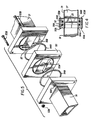
- the details of the compressor 30 and the nondestructive evaluator 32 are shown.
- the resonant frequency of the cavity 27 inside is adjusted by moving the slidable rear wall 28 with the handle 29 until a standing microwave field is established with a maximum amplitude of the electric field component at the joint J between samples S1 and S2.
- acoustic coupling agent e.g. grease
- acoustic magnifying lens 33 which maximizes the acoustic signal transferred to and from the sample S2 to and from a transducer 34.
- the transducer 34 converts electric pulses received from a transmitter or pulser 35 into acoustic pulses and sends these acoustic pulses along sample S2 to the joint J from which the acoustic pulses are reflected back through sample S2 to the acoustic magnifying lens 33 and the transducer 34. On the return trip, the transducer 34 converts the acoustic pulses back into electric pulses which are sent to a receiver 36. The output of the receiver 36 is then displayed on an oscilliscope 37.
- the compressor 30 and the evaluator 32 are both arranged outside the sealed chanber 21 which holds the samples S1 and S2 about which measurements are taken accurately without heat and radiation damage to such measuring instruments.
- a rear portion of the sealed chamber 21 is shown broken away to reveal the slidable rear wall 28 which adjusts the size of the cavity by moving the handle 29.
- the handle 29 is both guided and sealed by a fixed wall 41.
- Retaining plates 42 hold on O-ring 43 which securely seals the handle 29 against the introduction of any contaminants into the cavity 27 from the outside atmosphere.
- the cavity 27 in the sealed chamber 21 and an impendance matching section 51 extending between an iris plate 52 and the second circulator 17 (Fig. 1) is either evacuated or overpressurized through a vacuum/pressure line 44 on which a gage 45 is mounted to monitor the pressure in the line 44.
- the vacuum/pressure line 44 is preferably connected to the impedance matching section 51 because this arrangement provides convenient access to the chamber 21 without the necessity of disconnecting the line 44 every time such access is desired.
- the line 44 could be connected directly to the chamber 21 behind the iris 23.
- a first flow valve 46 is opened and a vacuum pump 47 is turned on when it is desired to evacuate the sealed chamber 21.
- the vacuum pump 47 must be able to reduce the pressure in the cavity 27 to less than 10 ⁇ 6 atmospheres to avoid Faraday discharge even at moderate microwave power levels.
- the first flow valve 46, second flow valve 48, and a pressurized inert gas cylinder 49 are opened when it is desired to overpressurize the sealed chamber 21.
- a preferred pressure in the cavity 27 is at least two atmospheres.
- Suitable inert gases contained in the cylinder 49 are nitrogen and argon.
- an exhaust valve 50 is opened so that either air flows into the evacuated chamber 21 or the pressurized inert gas flows out of the overpressurized chamber 21.
- joining may be accomplished in a normal atmospheric environment.
- it has been learned that it is necessary either to evacuate the sealed chamber 21 or to overpressurize the sealed chamber 21 with inert gas before proceeding in order to form a good bond.
- the iris 23 is an opening in a section of reduced thickness in the iris plate 52.
- the cavity 27 in the sealed chamber 21 is either evacuated or overpressurized through the iris 23.
- the iris plate 52 is connected between the sealed chamber 21 and the impedance matching section 51 by any suitable fastening means, such as conventional nuts 53A and bolts 53B.
- the iris plate 52 is sealed against leakage by a front O-ring 54A which fits into a circular groove 55A and by a rear O-ring 54B which fits into a circular groove 55B.
- Groove 55A has a complementary groove 55A on the face of the impedance matching section 51 while the groove 55B has a complementary groove 55B on the face of the sealed chamber 21.
- each viewing port 56 in the chamber 21 must be sealed against leakage of either air into or inert gas out of the chamber 21.
- the viewing port 56 is covered by a cap 57 having a plate 58 for retaining a window 59 thereover.
- the viewing port 56 is sealed against leakage past the cap 57 by an O-ring 60 while the cap 57 is sealed against leakage past the window 59 by another O-ring 61.
- the window 59 must be able to pass infrared radiation therethrough from the samples S1 and S2 with minimum attenuation.
- both conventional glass and transparent mica have been found to be sufficiently suitable.
- the sample S1 extends into the cavity from a top port 62 in the sealed chamber 21 while the sample S2 extends into the cavity from a bottom port 63 in the sealed chamber 21.
- the top port 62 has an O-ring 64 which seals the sample S1 against leakage while the bottom port 63 has a similar O-ring 65 which seals the sample S2 against leakage while the samples S1 and S2 are being joined at joint J.
- the elements described above constitute the components of the apparatus for the microwave joining of materials, such as nonoxide ceramics.
- the process may be explained as follows.
- the microwave energy propagates from the generating magnetron 11 along a waveguide schematically shown by the arrows to the sealed chamber 21.
- the standing wave of the microwave field has a maximum amplitude at three nearly equally spaced positions. At one of these positions, the nonoxide ceramic samples S1 and S2 are located so that they may absorb and dissipate as heat nearly all of the available microwave power.
- Variable coupling is achieved by selecting an iris 23 with a suitable opening so as to control the degree of coupling.
- the reason for using a sealed chamber 21 with a cavity 27 which is adjustable in length by a slidable rear wall 28 is that, as opposed to a terminated waveguide section, the power in the cavity 27 is Q times the power in the propagating microwave field where Q is the quality factor of the cavity 27 defined as the ratio of (2 ⁇ f) x (the average energy stored per cycle) to the power lost. Therefore , since Q may be several thousand units, the cavity 27 requires very little incident power to achieve a high level of stored energy and so a high level of energy is available to be dissipated by the samples S1 and S2. Of course, the energy dissipated can never exceed that associated with the microwave being propagated outside the cavity 27.
- thermocouple or thermistor cannot be inserted into the cavity 27 to measure the temperature of samples S1 and S2 because any conducting material introduced therein will behave as an antenna or a section of a coaxial transmission line which could conduct the microwave outside of the cavity 27.
- this phenomenon is the principle upon which the voltage coupling probes 14 and 24 are based.
- the noninvasive temperature measuring technique of the present invention is used, i.e. measuring the intensity of the infrared radiation emitted from the outer surface of the heated sample S2. This intensity is uniquely related, through Planck's radiation law, to the temperature at the surface of the material. Unfortunately, this relationship also depends on the emissivity of the surface.
- This emissivity is a measure of the radiative effectiveness of the surface such that, for a perfectly black surface, all radiation is either emitted or absorbed while, for a perfectly white surface, no radiation is either emitted or absorbed, i. e. it is all reflected internally or externally, respectively.
- the present invention employs a so-called "two-color" pyrometer 19 which causes such errors to be cancelled.
- Samples S1 and S2 were commercially obtained from the GTE-Wesgo Co.
- microwaves were supplied by the magnetron 11 and were transmitted through the rectangular waveguide schematically shown by the arrows to the impedance matching section 51 (Fig. 3) and the sealed chamber 21 having the cavity 27 in which the samples S1 and S2 were arranged.
- the cavity 27 supported a single mode microwave field configuration and had a resonant frequency which was varied by adjusting the rear wall 28 after the microwave field entered the cavity 27 through the iris 23.
- the power absorbed by the samples S1 and S2 was measured as the difference between the forward power focused into the cavity 27 and power reflected back out of the cavity 27.
- the samples S1 and S2 were placed at the maximum electric field amplitude of the standing microwave.
- the compressor 30, located outside the sealed chamber 21, provided force to the samples S1 and S2 during the joining process.
- a load cell 31 measured the force and transmitted its data to a force monitor and recorder 38 which displayed the data for the operator. While fabricating the bond, the power absorbed, the temperature reached, and the pressure applied were monitored and recorded appropriately on the recorder 18 of Fig. 1 and the recorder 38 of Fig. 2 as a function of time. These measurements were made to be sure that optimization of the power, temperature, and compression, each as a function of time, occurred during the joining process.
- the present invention is also capable of handling brazed ceramic to ceramic joints.
- nonoxide ceramic to metal joints there are two different types of joints possible, namely the conventional braze joint and an indirect braze joint using an interlayer.
- the position of the metal rod or other type of nonceramic specimen must first be carefully adjusted so that the end to be joined to the ceramic rod or specimen coincides with and becomes a part of an interior wall of the cavity 27 inside the chamber 21.
- the metal rod can then be inserted slightly through either the top port 62 or the bottom port 63 in the chamber 21.
- the metal rod inserted into the cavity 27 essentially serves as a capacitive post, and the electrical reactance of this post as well as its effect on the heating process can be computed with a high degree of accuracy.
- the nonoxide ceramic specimen can then be brought into contact with the metal specimen and heated in exactly the same manner as in the ceramic to ceramic bonding process because the bond will still be formed at the maximum electric field position of the cavity 27 which will have been retuned for the metal to nonoxide ceramic joining process. Note that the electric field is constant along the longitudinal axis of the cylindrical samples S1 and S2. Also, calculations of the temperature/time profile for the metal to ceramic joining process can still be made.
Applications Claiming Priority (2)
| Application Number | Priority Date | Filing Date | Title |
|---|---|---|---|
| US07/100,743 US4757172A (en) | 1986-09-24 | 1987-09-24 | Method and apparatus for the microwave joining of nonoxide ceramic items |
| US100743 | 1987-09-24 |
Publications (2)
| Publication Number | Publication Date |
|---|---|
| EP0308593A1 true EP0308593A1 (de) | 1989-03-29 |
| EP0308593B1 EP0308593B1 (de) | 1992-02-26 |
Family
ID=22281309
Family Applications (1)
| Application Number | Title | Priority Date | Filing Date |
|---|---|---|---|
| EP88110766A Expired - Lifetime EP0308593B1 (de) | 1987-09-24 | 1988-07-06 | Verfahren und Vorrichtung zur Verbindung von Gegenständen aus Nichtoxidkeramik mittels Mikrowellen |
Country Status (4)
| Country | Link |
|---|---|
| US (1) | US4757172A (de) |
| EP (1) | EP0308593B1 (de) |
| JP (1) | JPH0196072A (de) |
| DE (2) | DE3868574D1 (de) |
Cited By (2)
| Publication number | Priority date | Publication date | Assignee | Title |
|---|---|---|---|---|
| EP0329338A2 (de) * | 1988-02-16 | 1989-08-23 | Alcan International Limited | Verfahren und Vorrichtung zum Erhitzen von Körpern auf eine hohe Temperatur mittels Mikrowellen-Energie |
| WO1991005747A1 (en) * | 1989-10-19 | 1991-05-02 | Alcan International Limited | Method of heat-treating unstable ceramics by microwave heating and susceptors used therefor |
Families Citing this family (13)
| Publication number | Priority date | Publication date | Assignee | Title |
|---|---|---|---|---|
| CA1313230C (en) * | 1988-10-06 | 1993-01-26 | Raymond Roy | Process for heating materials by microwave energy |
| US5164130A (en) * | 1990-04-20 | 1992-11-17 | Martin Marietta Energy Systems, Inc. | Method of sintering ceramic materials |
| US5154779A (en) * | 1990-04-20 | 1992-10-13 | Martin Marietta Energy Systems, Inc. | Method of nitriding, carburizing, or oxidizing refractory metal articles using microwaves |
| US5108670A (en) * | 1990-04-20 | 1992-04-28 | Martin Marietta Energy Systems, Inc. | Process for making a titanium diboride-chromium diboride-yttrium titanium oxide ceramic composition |
| JPH05506066A (ja) * | 1990-04-20 | 1993-09-02 | マーチン・マリエッタ・エナジー・システムズ・インク | 耐熱性金属物品の窒化方法 |
| US5013694A (en) * | 1990-04-20 | 1991-05-07 | Martin Marietta Energy Systems, Inc. | Titanium diboride-chromium diboride-yttrium titanium oxide ceramic composition and a process for making the same |
| DE4324635A1 (de) * | 1993-07-22 | 1995-01-26 | Abb Patent Gmbh | Einrichtung zur Sinterung keramischer Körper mittels Mikrowellen |
| GB9324843D0 (en) * | 1993-12-03 | 1994-01-19 | Ray Ronnie A | Apparatus for performing chemical reaction |
| US5532462A (en) * | 1994-04-29 | 1996-07-02 | Communications & Power Industries | Method of and apparatus for heating a reaction vessel with microwave energy |
| US6242726B1 (en) * | 1996-11-21 | 2001-06-05 | George M. Harris | Adjustable microwave field stop |
| EP0979595B1 (de) * | 1997-04-10 | 2007-07-04 | Nucon Systems Inc. | Verfahren und vorrichtung zur verbindung von keramischen dickwändigen stücken durch mikrowellen |
| US7022198B2 (en) * | 2003-03-07 | 2006-04-04 | The United States Of America As Represented By The Secretary Of The Navy | Microwave assisted reactive brazing of ceramic materials |
| DE102007044503B4 (de) | 2007-09-18 | 2018-09-13 | Robert Bosch Gmbh | Fügeverfahren |
Citations (5)
| Publication number | Priority date | Publication date | Assignee | Title |
|---|---|---|---|---|
| US4420352A (en) * | 1983-02-10 | 1983-12-13 | The United States Of America As Represented By The Administrator Of The National Aeronautics And Space Administration | Absorbable-susceptor joining of ceramic surfaces |
| US4529856A (en) * | 1983-10-04 | 1985-07-16 | The United States Of America As Represented By The United States Department Of Energy | Ceramic-glass-metal seal by microwave heating |
| US4529857A (en) * | 1983-10-04 | 1985-07-16 | The United States Of America As Represented By The United States Department Of Energy | Ceramic-glass-ceramic seal by microwave heating |
| EP0251256A1 (de) * | 1986-06-30 | 1988-01-07 | Kabushiki Kaisha Toyota Chuo Kenkyusho | Vorrichtung für das Verbinden von Keramik mittels Mikrowellen |
| EP0261928A2 (de) * | 1986-09-24 | 1988-03-30 | Questech Inc. | Verfahren und Vorrichtung für die Verbindung von keramischen Körpern durch Mikrowellen |
Family Cites Families (16)
| Publication number | Priority date | Publication date | Assignee | Title |
|---|---|---|---|---|
| US3469053A (en) * | 1965-10-19 | 1969-09-23 | Melvin L Levinson | Microwave kiln |
| US3520055A (en) * | 1967-04-26 | 1970-07-14 | Western Electric Co | Method for holding workpieces for radiant energy bonding |
| FR2079945A5 (de) * | 1970-02-18 | 1971-11-12 | Materiel Telephonique | |
| US3755065A (en) * | 1971-05-11 | 1973-08-28 | Owens Illinois Inc | Oxidic solder sealing compositions and their use in forming laminates |
| US3998632A (en) * | 1972-04-27 | 1976-12-21 | Valentin Petrovich Kosteruk | Metal alloy |
| US3841870A (en) * | 1973-03-07 | 1974-10-15 | Carpenter Technology Corp | Method of making articles from powdered material requiring forming at high temperature |
| US4003368A (en) * | 1974-06-27 | 1977-01-18 | Armco Steel Corporation | Article transparent to microwaves and process for making same |
| US3953703A (en) * | 1974-10-03 | 1976-04-27 | Materials Research Corporation | Method for drying ceramic tape |
| JPS5823349B2 (ja) * | 1975-08-11 | 1983-05-14 | 新日本製鐵株式会社 | タイカブツノシヨウケツホウホウ |
| US4179596A (en) * | 1978-04-27 | 1979-12-18 | Litton Systems, Inc. | Method for processing fiberoptic electronic components of electronic vacuum devices |
| US4219361A (en) * | 1978-06-09 | 1980-08-26 | Special Metals Corporation | Method of improving the susceptibility of a material to microwave energy heating |
| US4307277A (en) * | 1978-08-03 | 1981-12-22 | Mitsubishi Denki Kabushiki Kaisha | Microwave heating oven |
| US4273950A (en) * | 1979-05-29 | 1981-06-16 | Photowatt International, Inc. | Solar cell and fabrication thereof using microwaves |
| US4292262A (en) * | 1979-06-28 | 1981-09-29 | Tobin Jr Leo W | Ceramic material processing |
| US4347089A (en) * | 1981-07-29 | 1982-08-31 | Sri International | Method for bonding silicon nitride |
| US4384909A (en) * | 1981-11-16 | 1983-05-24 | United Technologies Corporation | Bonding Si3 N4 ceramics |
-
1987
- 1987-09-24 US US07/100,743 patent/US4757172A/en not_active Expired - Fee Related
-
1988
- 1988-07-06 DE DE8888110766T patent/DE3868574D1/de not_active Expired - Fee Related
- 1988-07-06 DE DE198888110766T patent/DE308593T1/de active Pending
- 1988-07-06 EP EP88110766A patent/EP0308593B1/de not_active Expired - Lifetime
- 1988-07-07 JP JP63167897A patent/JPH0196072A/ja active Granted
Patent Citations (5)
| Publication number | Priority date | Publication date | Assignee | Title |
|---|---|---|---|---|
| US4420352A (en) * | 1983-02-10 | 1983-12-13 | The United States Of America As Represented By The Administrator Of The National Aeronautics And Space Administration | Absorbable-susceptor joining of ceramic surfaces |
| US4529856A (en) * | 1983-10-04 | 1985-07-16 | The United States Of America As Represented By The United States Department Of Energy | Ceramic-glass-metal seal by microwave heating |
| US4529857A (en) * | 1983-10-04 | 1985-07-16 | The United States Of America As Represented By The United States Department Of Energy | Ceramic-glass-ceramic seal by microwave heating |
| EP0251256A1 (de) * | 1986-06-30 | 1988-01-07 | Kabushiki Kaisha Toyota Chuo Kenkyusho | Vorrichtung für das Verbinden von Keramik mittels Mikrowellen |
| EP0261928A2 (de) * | 1986-09-24 | 1988-03-30 | Questech Inc. | Verfahren und Vorrichtung für die Verbindung von keramischen Körpern durch Mikrowellen |
Cited By (4)
| Publication number | Priority date | Publication date | Assignee | Title |
|---|---|---|---|---|
| EP0329338A2 (de) * | 1988-02-16 | 1989-08-23 | Alcan International Limited | Verfahren und Vorrichtung zum Erhitzen von Körpern auf eine hohe Temperatur mittels Mikrowellen-Energie |
| EP0329338A3 (de) * | 1988-02-16 | 1990-08-01 | Alcan International Limited | Verfahren und Vorrichtung zum Erhitzen von Körpern auf eine hohe Temperatur mittels Mikrowellen-Energie |
| US5010220A (en) * | 1988-02-16 | 1991-04-23 | Alcan International Limited | Process and apparatus for heating bodies at high temperature and pressure utilizing microwave energy |
| WO1991005747A1 (en) * | 1989-10-19 | 1991-05-02 | Alcan International Limited | Method of heat-treating unstable ceramics by microwave heating and susceptors used therefor |
Also Published As
| Publication number | Publication date |
|---|---|
| JPH052632B2 (de) | 1993-01-12 |
| DE3868574D1 (de) | 1992-04-02 |
| DE308593T1 (de) | 1989-09-14 |
| JPH0196072A (ja) | 1989-04-14 |
| US4757172A (en) | 1988-07-12 |
| EP0308593B1 (de) | 1992-02-26 |
Similar Documents
| Publication | Publication Date | Title |
|---|---|---|
| US4767902A (en) | Method and apparatus for the microwave joining of ceramic items | |
| US4757172A (en) | Method and apparatus for the microwave joining of nonoxide ceramic items | |
| US5170666A (en) | Nondestructive evaluation of composite materials using acoustic emissions stimulated by absorbed microwave/radiofrequency energy | |
| Shepard et al. | Experimental considerations in vibrothermography | |
| EP0840110B1 (de) | Zerstörungsfreies Prüfen: transiente, tiefenauflösende Thermographie | |
| US5469742A (en) | Acoustic temperature and film thickness monitor and method | |
| EP0012262A1 (de) | Vorrichtung und Verfahren zur akustischen Prüfung eines mikroskopisch kleinen Teils eines Objekts | |
| US20090000382A1 (en) | Non-contact acousto-thermal method and apparatus for detecting incipient damage in materials | |
| JP2001242110A (ja) | 圧電セラミック素子の検査方法 | |
| Bloomquist et al. | Thermocouple temperature measurements in shock‐compressed solids | |
| Palaith et al. | Microwave joining of ceramics | |
| Maruyama et al. | Elastic modulus and bend strength of a nuclear graphite at high temperature | |
| Reynolds | Inspection of laminates and adhesive bonds by pulse-video thermography | |
| Tittmann et al. | Ultrasonic sensors for high temperature applications | |
| US5374122A (en) | Method for quantifying porosity of parts of simple and complex geometries | |
| Ono et al. | High-temperature and broadband immersion ultrasonic probes | |
| Stubbs et al. | High-temperature ultrasonic sensor for in-situ monitoring of hot isostatic processing | |
| KR920007199B1 (ko) | 비파괴 검사방법 및 장치 | |
| JP2545974B2 (ja) | スペクトラム超音波顕微鏡 | |
| JPH028736A (ja) | 衝撃波超音波装置 | |
| JPS59221657A (ja) | セラミツクス製品の品質検査法 | |
| Green et al. | THERMAL AND ULTRASONIC NONDESTRUCTIVE TESTING METHODS FOR CARBON--CARBON COMPOSITES. | |
| GB2258304A (en) | Measurement of thermal inhomogeneities | |
| JPS59221661A (ja) | セラミツクス接合部の欠陥検査法 | |
| JPH11166917A (ja) | 重ね抵抗溶接部の溶接状態検査方法および装置 |
Legal Events
| Date | Code | Title | Description |
|---|---|---|---|
| PUAI | Public reference made under article 153(3) epc to a published international application that has entered the european phase |
Free format text: ORIGINAL CODE: 0009012 |
|
| AK | Designated contracting states |
Kind code of ref document: A1 Designated state(s): DE FR GB IT SE |
|
| EL | Fr: translation of claims filed | ||
| 17P | Request for examination filed |
Effective date: 19890622 |
|
| ITCL | It: translation for ep claims filed |
Representative=s name: STUDIO BUGNION S.P.A. |
|
| DET | De: translation of patent claims | ||
| RAP1 | Party data changed (applicant data changed or rights of an application transferred) |
Owner name: QUESTECH INC. |
|
| REG | Reference to a national code |
Ref country code: DE Ref legal event code: 8580 Free format text: ES ERFOLGT ERGAENZUNGSDRUCK DER FEHLENDEN ANSPRUECHEN 57 - 62 |
|
| 17Q | First examination report despatched |
Effective date: 19910212 |
|
| GRAA | (expected) grant |
Free format text: ORIGINAL CODE: 0009210 |
|
| AK | Designated contracting states |
Kind code of ref document: B1 Designated state(s): DE FR GB IT SE |
|
| ITF | It: translation for a ep patent filed |
Owner name: BUGNION S.P.A. |
|
| REF | Corresponds to: |
Ref document number: 3868574 Country of ref document: DE Date of ref document: 19920402 |
|
| ET | Fr: translation filed | ||
| PLBE | No opposition filed within time limit |
Free format text: ORIGINAL CODE: 0009261 |
|
| STAA | Information on the status of an ep patent application or granted ep patent |
Free format text: STATUS: NO OPPOSITION FILED WITHIN TIME LIMIT |
|
| 26N | No opposition filed | ||
| EAL | Se: european patent in force in sweden |
Ref document number: 88110766.8 |
|
| PGFP | Annual fee paid to national office [announced via postgrant information from national office to epo] |
Ref country code: FR Payment date: 19970526 Year of fee payment: 10 |
|
| PGFP | Annual fee paid to national office [announced via postgrant information from national office to epo] |
Ref country code: SE Payment date: 19970610 Year of fee payment: 10 Ref country code: GB Payment date: 19970610 Year of fee payment: 10 |
|
| PGFP | Annual fee paid to national office [announced via postgrant information from national office to epo] |
Ref country code: DE Payment date: 19970717 Year of fee payment: 10 |
|
| PG25 | Lapsed in a contracting state [announced via postgrant information from national office to epo] |
Ref country code: GB Free format text: LAPSE BECAUSE OF NON-PAYMENT OF DUE FEES Effective date: 19980706 |
|
| PG25 | Lapsed in a contracting state [announced via postgrant information from national office to epo] |
Ref country code: SE Free format text: LAPSE BECAUSE OF NON-PAYMENT OF DUE FEES Effective date: 19980707 |
|
| GBPC | Gb: european patent ceased through non-payment of renewal fee |
Effective date: 19980706 |
|
| EUG | Se: european patent has lapsed |
Ref document number: 88110766.8 |
|
| PG25 | Lapsed in a contracting state [announced via postgrant information from national office to epo] |
Ref country code: FR Free format text: LAPSE BECAUSE OF NON-PAYMENT OF DUE FEES Effective date: 19990331 |
|
| PG25 | Lapsed in a contracting state [announced via postgrant information from national office to epo] |
Ref country code: DE Free format text: LAPSE BECAUSE OF NON-PAYMENT OF DUE FEES Effective date: 19990501 |
|
| REG | Reference to a national code |
Ref country code: FR Ref legal event code: ST |
|
| PG25 | Lapsed in a contracting state [announced via postgrant information from national office to epo] |
Ref country code: IT Free format text: LAPSE BECAUSE OF NON-PAYMENT OF DUE FEES;WARNING: LAPSES OF ITALIAN PATENTS WITH EFFECTIVE DATE BEFORE 2007 MAY HAVE OCCURRED AT ANY TIME BEFORE 2007. THE CORRECT EFFECTIVE DATE MAY BE DIFFERENT FROM THE ONE RECORDED. Effective date: 20050706 |