EP0308512B1 - Appareil pour le matage de rouleaux par un faisceau laser a impulsions - Google Patents
Appareil pour le matage de rouleaux par un faisceau laser a impulsions Download PDFInfo
- Publication number
- EP0308512B1 EP0308512B1 EP88902201A EP88902201A EP0308512B1 EP 0308512 B1 EP0308512 B1 EP 0308512B1 EP 88902201 A EP88902201 A EP 88902201A EP 88902201 A EP88902201 A EP 88902201A EP 0308512 B1 EP0308512 B1 EP 0308512B1
- Authority
- EP
- European Patent Office
- Prior art keywords
- pulse
- laser
- roll
- dulling
- osc1
- Prior art date
- Legal status (The legal status is an assumption and is not a legal conclusion. Google has not performed a legal analysis and makes no representation as to the accuracy of the status listed.)
- Expired - Lifetime
Links
- 101100339482 Colletotrichum orbiculare (strain 104-T / ATCC 96160 / CBS 514.97 / LARS 414 / MAFF 240422) HOG1 gene Proteins 0.000 claims description 11
- 101100500049 Saccharomyces cerevisiae (strain ATCC 204508 / S288c) YSR3 gene Proteins 0.000 claims description 6
- 101100048228 Homo sapiens UBP1 gene Proteins 0.000 claims description 4
- 101100117629 Saccharomyces cerevisiae (strain ATCC 204508 / S288c) LCB3 gene Proteins 0.000 claims description 4
- 102100040065 Upstream-binding protein 1 Human genes 0.000 claims description 4
- 230000001960 triggered effect Effects 0.000 claims 1
- 238000000034 method Methods 0.000 abstract description 20
- 238000007796 conventional method Methods 0.000 abstract description 5
- 230000005284 excitation Effects 0.000 abstract description 4
- 230000010355 oscillation Effects 0.000 abstract description 3
- 238000005452 bending Methods 0.000 description 9
- 238000010586 diagram Methods 0.000 description 7
- 238000010276 construction Methods 0.000 description 6
- 230000002829 reductive effect Effects 0.000 description 6
- 229910000831 Steel Inorganic materials 0.000 description 5
- 239000010959 steel Substances 0.000 description 5
- VYPSYNLAJGMNEJ-UHFFFAOYSA-N Silicium dioxide Chemical compound O=[Si]=O VYPSYNLAJGMNEJ-UHFFFAOYSA-N 0.000 description 4
- 230000000694 effects Effects 0.000 description 4
- 238000001704 evaporation Methods 0.000 description 4
- 230000008020 evaporation Effects 0.000 description 4
- 230000003287 optical effect Effects 0.000 description 4
- 229910052698 phosphorus Inorganic materials 0.000 description 4
- 238000000926 separation method Methods 0.000 description 4
- 229910052717 sulfur Inorganic materials 0.000 description 4
- 238000005299 abrasion Methods 0.000 description 3
- 230000003247 decreasing effect Effects 0.000 description 3
- 238000005553 drilling Methods 0.000 description 3
- 239000007789 gas Substances 0.000 description 3
- 238000005086 pumping Methods 0.000 description 3
- 238000005096 rolling process Methods 0.000 description 3
- 239000007787 solid Substances 0.000 description 3
- 230000003746 surface roughness Effects 0.000 description 3
- 238000012546 transfer Methods 0.000 description 3
- XKRFYHLGVUSROY-UHFFFAOYSA-N Argon Chemical compound [Ar] XKRFYHLGVUSROY-UHFFFAOYSA-N 0.000 description 2
- IJGRMHOSHXDMSA-UHFFFAOYSA-N Atomic nitrogen Chemical compound N#N IJGRMHOSHXDMSA-UHFFFAOYSA-N 0.000 description 2
- 238000009825 accumulation Methods 0.000 description 2
- 230000005540 biological transmission Effects 0.000 description 2
- 230000015572 biosynthetic process Effects 0.000 description 2
- 238000012937 correction Methods 0.000 description 2
- 239000005350 fused silica glass Substances 0.000 description 2
- 238000003754 machining Methods 0.000 description 2
- 239000010979 ruby Substances 0.000 description 2
- 229910001750 ruby Inorganic materials 0.000 description 2
- 239000006096 absorbing agent Substances 0.000 description 1
- 230000002411 adverse Effects 0.000 description 1
- 229910052786 argon Inorganic materials 0.000 description 1
- QVGXLLKOCUKJST-UHFFFAOYSA-N atomic oxygen Chemical compound [O] QVGXLLKOCUKJST-UHFFFAOYSA-N 0.000 description 1
- 238000005422 blasting Methods 0.000 description 1
- 230000000903 blocking effect Effects 0.000 description 1
- 238000006243 chemical reaction Methods 0.000 description 1
- 230000007423 decrease Effects 0.000 description 1
- 230000001934 delay Effects 0.000 description 1
- -1 e.g. Substances 0.000 description 1
- 238000005265 energy consumption Methods 0.000 description 1
- 238000002474 experimental method Methods 0.000 description 1
- 230000004907 flux Effects 0.000 description 1
- 230000002401 inhibitory effect Effects 0.000 description 1
- 238000009434 installation Methods 0.000 description 1
- 239000000463 material Substances 0.000 description 1
- 239000000155 melt Substances 0.000 description 1
- 229910052757 nitrogen Inorganic materials 0.000 description 1
- 239000001301 oxygen Substances 0.000 description 1
- 229910052760 oxygen Inorganic materials 0.000 description 1
- 230000010287 polarization Effects 0.000 description 1
- 238000007788 roughening Methods 0.000 description 1
- 239000000377 silicon dioxide Substances 0.000 description 1
- 239000000126 substance Substances 0.000 description 1
- 230000001360 synchronised effect Effects 0.000 description 1
Images


Classifications
-
- C—CHEMISTRY; METALLURGY
- C21—METALLURGY OF IRON
- C21D—MODIFYING THE PHYSICAL STRUCTURE OF FERROUS METALS; GENERAL DEVICES FOR HEAT TREATMENT OF FERROUS OR NON-FERROUS METALS OR ALLOYS; MAKING METAL MALLEABLE, e.g. BY DECARBURISATION OR TEMPERING
- C21D9/00—Heat treatment, e.g. annealing, hardening, quenching or tempering, adapted for particular articles; Furnaces therefor
- C21D9/38—Heat treatment, e.g. annealing, hardening, quenching or tempering, adapted for particular articles; Furnaces therefor for roll bodies
-
- B—PERFORMING OPERATIONS; TRANSPORTING
- B23—MACHINE TOOLS; METAL-WORKING NOT OTHERWISE PROVIDED FOR
- B23K—SOLDERING OR UNSOLDERING; WELDING; CLADDING OR PLATING BY SOLDERING OR WELDING; CUTTING BY APPLYING HEAT LOCALLY, e.g. FLAME CUTTING; WORKING BY LASER BEAM
- B23K26/00—Working by laser beam, e.g. welding, cutting or boring
- B23K26/02—Positioning or observing the workpiece, e.g. with respect to the point of impact; Aligning, aiming or focusing the laser beam
- B23K26/06—Shaping the laser beam, e.g. by masks or multi-focusing
- B23K26/0604—Shaping the laser beam, e.g. by masks or multi-focusing by a combination of beams
- B23K26/0608—Shaping the laser beam, e.g. by masks or multi-focusing by a combination of beams in the same heat affected zone [HAZ]
-
- B—PERFORMING OPERATIONS; TRANSPORTING
- B23—MACHINE TOOLS; METAL-WORKING NOT OTHERWISE PROVIDED FOR
- B23K—SOLDERING OR UNSOLDERING; WELDING; CLADDING OR PLATING BY SOLDERING OR WELDING; CUTTING BY APPLYING HEAT LOCALLY, e.g. FLAME CUTTING; WORKING BY LASER BEAM
- B23K26/00—Working by laser beam, e.g. welding, cutting or boring
- B23K26/02—Positioning or observing the workpiece, e.g. with respect to the point of impact; Aligning, aiming or focusing the laser beam
- B23K26/06—Shaping the laser beam, e.g. by masks or multi-focusing
- B23K26/0604—Shaping the laser beam, e.g. by masks or multi-focusing by a combination of beams
- B23K26/0613—Shaping the laser beam, e.g. by masks or multi-focusing by a combination of beams having a common axis
-
- B—PERFORMING OPERATIONS; TRANSPORTING
- B23—MACHINE TOOLS; METAL-WORKING NOT OTHERWISE PROVIDED FOR
- B23K—SOLDERING OR UNSOLDERING; WELDING; CLADDING OR PLATING BY SOLDERING OR WELDING; CUTTING BY APPLYING HEAT LOCALLY, e.g. FLAME CUTTING; WORKING BY LASER BEAM
- B23K26/00—Working by laser beam, e.g. welding, cutting or boring
- B23K26/02—Positioning or observing the workpiece, e.g. with respect to the point of impact; Aligning, aiming or focusing the laser beam
- B23K26/06—Shaping the laser beam, e.g. by masks or multi-focusing
- B23K26/062—Shaping the laser beam, e.g. by masks or multi-focusing by direct control of the laser beam
- B23K26/0622—Shaping the laser beam, e.g. by masks or multi-focusing by direct control of the laser beam by shaping pulses
-
- B—PERFORMING OPERATIONS; TRANSPORTING
- B23—MACHINE TOOLS; METAL-WORKING NOT OTHERWISE PROVIDED FOR
- B23K—SOLDERING OR UNSOLDERING; WELDING; CLADDING OR PLATING BY SOLDERING OR WELDING; CUTTING BY APPLYING HEAT LOCALLY, e.g. FLAME CUTTING; WORKING BY LASER BEAM
- B23K26/00—Working by laser beam, e.g. welding, cutting or boring
- B23K26/08—Devices involving relative movement between laser beam and workpiece
- B23K26/0823—Devices involving rotation of the workpiece
-
- B—PERFORMING OPERATIONS; TRANSPORTING
- B23—MACHINE TOOLS; METAL-WORKING NOT OTHERWISE PROVIDED FOR
- B23K—SOLDERING OR UNSOLDERING; WELDING; CLADDING OR PLATING BY SOLDERING OR WELDING; CUTTING BY APPLYING HEAT LOCALLY, e.g. FLAME CUTTING; WORKING BY LASER BEAM
- B23K26/00—Working by laser beam, e.g. welding, cutting or boring
- B23K26/352—Working by laser beam, e.g. welding, cutting or boring for surface treatment
- B23K26/355—Texturing
-
- B—PERFORMING OPERATIONS; TRANSPORTING
- B21—MECHANICAL METAL-WORKING WITHOUT ESSENTIALLY REMOVING MATERIAL; PUNCHING METAL
- B21B—ROLLING OF METAL
- B21B2267/00—Roll parameters
- B21B2267/10—Roughness of roll surface
-
- B—PERFORMING OPERATIONS; TRANSPORTING
- B21—MECHANICAL METAL-WORKING WITHOUT ESSENTIALLY REMOVING MATERIAL; PUNCHING METAL
- B21B—ROLLING OF METAL
- B21B27/00—Rolls, roll alloys or roll fabrication; Lubricating, cooling or heating rolls while in use
- B21B27/005—Rolls with a roughened or textured surface; Methods for making same
Definitions
- the present invention relates to apparatus for dulling a surface of an article such as a roll by a laser beam and, in particular, ensuring appropriate conditions for such dulling by controlling a pulse waveform of a Q-switched laser beam.
- the methods of dulling a roll include, among others, shot-blasting electric discharge machining, and working the roll surface by a laser.
- JP-B-58-25557 and JP-B-60-2156 disclose apparatus for dulling the surface of a roll with a pulsed laser beam projected from a laser source of a YAG laser, ruby laser, or the like by Q-switching, and are characterized by providing a laser beam splitter which irradiates the surface of a rotating roll (JP-B-58-25557) and controls a number of laser beam pulses emitted from the laser beam splitter in accordance with a dulling shape (JP-B-60-2156).
- JP-B-60-2156 discloses apparatus which produces a pulsed laser beam by Q-switching of a continuous-wave laser beam and this apparatus includes a Q-switch control system with a pulse oscillator for determining pulse repetition and the output power of a radio-frequency signal source.
- the roll surface must be worked periodically with a pulse laser having a predetermined repetition rate, pulse width and peak value.
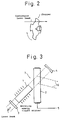
- Such a pulse laser output can be provided by pulsing a continuous-wave (CW) laser output using a mechanical optical apparatus (chopper, shutter, etc.) as shown in Figure 2, or by using a pulse laser or Q-switched laser beam (as shown in Figure 3).
- JP-A-58-79788 describes one method of driving a Q-switched laser unit for use in precision machining and other fields.
- the equipment can be made compact and simple and the pulse repetition rate can be easily controlled over a wide range, in comparison with other methods.
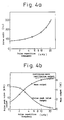
- the frequency is changed by the Q-switching, as shown in Figure 4a and Figure 4b, since the oscillation and excitation conditions vary, the pulse waveform and peak value output are also varied at the same time, and thus a stable dulling cannot be obtained.
- the peak value (Pl1) of the leading pulse is very much larger than those of the subsequent pulses (Pl2 , Pl3 , Pl4 , ---), as shown in Figure 1a.
- JP-B-58-25557 and JP-B- 60-2156 mentioned above do not disclose a solution to the above problems of the conventional techniques.
- the dulling of a roll surface of a rolling mill is disclosed in other published documents, e.g., JP-B-61-28436 and US-A-4329562.
- JP-B-61-28436 discloses a process in which two luminous fluxes are intermittently focused a lens through a circular rotating plate having a transmission zone and a reflection zone, onto the roll surface
- US-A-4329562 discloses a process by which a specific motif or motif patterns are formed on the roll surface of the rolling mill.
- the invention enables a crater of a desired shape to be formed efficiently on the roll surface by controlling the nonuniformity, the pulse peak value, and the half-width value of the pulse waveform of a Q-switched pulse laser, which are the problems of the conventional techniques as mentioned above, to the respective domains thereof suitable for dulling a roll, and increases the efficiency of the control of not only a single pulse but also a pulse group.
- a desired excitation energy (light source) is continuously applied to a laser rod 1 arranged between reflecting mirror 3 and 4, and when a Q-switched element 2 composed of a fused quartz, an absorber, and an acousto-optic modulator and disposed between the laser rod 1 and the reflecting mirror 4 at a predetermined angle to a laser optical resonating axis, is supplied with a high frequency signal (this signal is modulated by an RF output modulated signal) from a radio frequency signal source (RF) 5, a diffraction grating is formed inside the fused quarty to generate a diffracted light 6.
- RF radio frequency signal source
- the loss inside the resonator 7 is increased and the energy is accumulated in the laser rod 1. Then, when the RF signal applied to the Q-switched element is turned off by an RF output modulated signal, the diffraction grating in the fused quartz is extinguished and the diffraction light 6 eliminated, and the loss in the resonator 7 is decreased. As a result, the energy accumulated in the laser rod 1 is instantaneously radiated to provide a laser pulse having a high pulse peak value.
- the energy at a level E max is accumulated in the laser rod 1, and when this energy is instantaneously discharged to a level E min ( ⁇ 0 W), the laser output forms a laser pulse having a high pulse peak value of from P min to P max .
- the pulse peak value and half width, etc., of the subsequent pulse can be controlled by controlling the accumulation of energy (E max ) of the laser rod 1, the inventors of the present invention effected the following methods:
- the method (2)-1 requires an advanced technique for adjustment of the angle and position of the Q-switching element, the method (2)-2 is not advantageous in that the energy consumption is large, and the method (2)-3 is the simplest and most desirable.
- Figure 9 shows the above and indicates the correction between the leakage output P L and the average pulse peak value P p ⁇ and the pulse half width t p . It is proven that, when the leakage output P L is increased, the average pulse peak value P p is reduced as shown by curve A and the pulse half width is increased as shown by curve B.
- the leakage output is increased, and therefore, the average pulse peak value is reduced and the first pulse peak value is reduced and thus the first pulse peak value can be maintained at a same level as another pulse peak value in a group.
- the pulse half width can be increased, and therefore, when the roll surface is dulled by this invention, desired craters can be formed.
- Figure 7(b) shows the above craters, and thermally-affected zones 12 caused by the leakage output formed on the roll surface.
- the concavity of the craters can impart a desired roughness to the surface of a rolled steel plates, and since the thermally-affected zones 12 have no irregularities, the rolling of a steel plate can be effected without an adverse affect thereon.
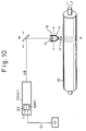
- a pulsed laser beam oscillator (OSC) 7 of the roll-dulling apparatus of the present invention comprises a YAG laser oscillator having an average output of over 100 [W] and can oscillate a Q-switched pulsed laser beam LB having a frequency of 1-40 kHz.
- the laser beam LB is made incident onto the roll surface by a plurality of bending mirrors M (only one mirror shown in the drawing) and a focusing lens FL.
- a laser beam incident head 13 is moved roll-axially by a drive mechanism (not shown).
- a nozzle 14 is set at a top of the laser beam incident head to emit a gas, e.g., nitrogen, oxygen or argon gas, supplied from a gas supply source (not shown).
- the Q-switch QS comprises the Q switching element 2 and the radio frequency signal source (RF) 5.
- Reference numeral 10 indicates a controlling system comprised of a circuit which generates the RF output modulated signal Q.
- the pulsed laser beam LB generated by the oscillator, as described herebelow, is made incident on the surface of the roll 20, which is rotating at a constant speed.
- the signal Q generated from the controlling system 10 is input to the radio frequency signal source RF 5, and the signal is modulated to a desired waveform at the signal source 5 and applied to the Q-switching element 2, where the RF output is controlled (lowered) and the pulse waveform shown in Figure 1b, for example, is generated.
- the pulsed laser beam LB generated in accordance with the above pulse waveform is made incident on the roll surface.
- the most suitable pulsed laser beam for dulling can be irradiated and a crater-shape type motif A can be formed.
- the pulsed laser beam incident head 13 is moved at a constant speed by a drive mechanism, the above mentioned pulsed laser beam is irradiated, and the motif A can be formed on the surface of the roll 20 at regular intervals and as a constant pattern.
- craters were formed, having a height of the concavity h of 2 to 3 »m, a depth d of 5 to 10 »m, and a diameter D of 100 to 200 »m, as shown in Figure 7b.
- the leakage output became 30 W and an output of 40 W was used to form the pulse.
- the output used to form the pulse was 30% higher, the melt evaporation was increased, the unevenness of the craters was decreased, in that h was 1 to 2 »m, d was 2 to 6 »m, and D was 100 to 200 »m.
- a first embodiment of apparatus according to the invention, for roll-dulling by a pulsed laser beam, will now be described in detail with reference to Figure 11, in which a group of laser beams is formed by oscillating a plurality of Q-switched laser beams produced by a Q-switched control system.
- FIG 11 shows the basic construction of a pulsed laser beam controller according to the present invention, in which four pulses are used.
- OSC1 to OSC4 indicate laser oscillators
- OS1 to OS4 indicate Q-switches containing the high frequency signal sources RF and corresponding to the oscillators OSC1 to OSC4.
- Reference number 10 indicates a control system for the Q-switches, from which Q-switched signals Q1 to Q4 are output.
- Laser beams LB1 to LB4 are generated by the oscillators OSC1 to OSC4 and combined into a group LBP of parallel laser beams by bending mirrors M1 to M7 and combining mirrors TM1 to TM3.
- the laser beam group LBP is focused by a focusing lens FL into a focused laser beam group LFP at a focal point FP0 in such a manner that a single beam is formed.
- Reference numeral 20 indicates the surface of a roll to be worked. Although four laser beams are shown in Figure 11, the number of laser beams is not limited thereto, since when the number of laser beam is increased, the depth of a hole is almost linearly increased, and thus the number of laser beams is selected according to the quality of the roll surface roughness to be dulled.
- Figure 12 shows the ideal pulse waveform for dulling the roll surface.
- the symbol ⁇ 0 indicates the width of each laser pulse
- ⁇ 1 indicates the interval between the first pulse PL1 and second pulse PL2
- ⁇ 2 indicates the interval between the second pulse PL2 and third pulse PL3.
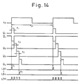
- a circuit diagram of the Q-switch control system 10 is shown in Figure 13, and a functional time chart of the control signals is shown in Figure 14.
- the circuit of the Q-switch control system consists of a Pulse generator PG for determining a frequency f0 of the pulse group, and one-shot multivibrators OM1 to OM4 for determining the pulse intervals ⁇ 1 to ⁇ 3 in the pulse group.
- OM1 to OM4 are synchronous with leading edges of the respective input signals thereof.
- the output signal f0 from the pulse generator PG is supplied to the clock CK1 of OM1 , whereby a pulse Q1 of the pulse interval ⁇ 1 set at the OM1 synchronously with the leading edge of the output signal f0 is generated, and simultaneously, a signal Q, having an opposite polarity to that of the pulse Q1 is delivered and supplied to the clock CK2 of OM2; the pulses Q2 and Q2 are produced in the same way. This also holds true for OM3 and OM4.
- the frequency f0 of the pulse group for dulling is set by PG, and a group of pulses with a predetermined time delay therebetween is generated synchronously with the first signal, and the above pulses Q1 to Q4 control a generated signal of the high frequency signal source RF in the Q-switches QS1 to QS2 , to thereby effect a control of the Q-switches for the laser beams LB1 to LB4.
- a roll was dulled by controlling the pulse waveforms of four Q-switched laser beams by the method of the present invention.
- the waveform controlling conditions of the Q-switched laser pulse beam were as follows: ⁇ 1 to ⁇ 3: 5 »s LB1 - LB4: 2 kW f0: 20 kHz FL: 25 mm RF output: 40%
- the results of the dulling were a bore diameter of 100 »m and a roughness of 5 »m.
- the transfer to the steel plate was as high as 80% and the abrasion resistance was also improved.
- a peak value can be set for each pulse of a pulse group, the fusing and evaporation during the process of dulling an object to be worked in the drilling process for roughening the surface of the object can be effectively controlled and craters having suitable shape and hardness can be formed.
- a height of a concavity of a crater of more than 5 »m can be constantly formed.
- the pulse interval in the pulse group can be controlled, a drilling suitable for dulling can be conducted. Namely, the present invention is very effective for use in roll dulling.
- a respective beam pulse expander BX is set between each laser oscillator OSC and the respective bending mirror BM and therefore, in addition to the effect of the previous embodiment, the diameters of the laser beams (the product beam diameter D and the divergence angle ⁇ is constant) are enlarged, respectively.
- Figure 15 shows the basic construction of the pulse laser controller using four pulses, wherein OSC1 to OSC4 indicate respective laser oscillators, and QS1 to QS4 indicate respective Q-switches, corresponding to the oscillators OSC1 to OSC4, respectively.
- Reference numeral 10 indicates a Q-switch control system which delivers Q-switching signals Q1 to Q4, and laser beams LB1 to LB4 are generated from the oscillators OSC1 to OSC4.
- the laser beams LB1 to LB4 have diameters enlarged, respectively, by the beam pulse expanders BX1 to BX4 so that the laser beams LB1 to LB4 have divergence angles of ⁇ 1 to ⁇ 4.
- These laser beams LB1 to LB4 are merged into a single laser beam group LBP by bending mirrors BM1 to BM6 and combining mirrors MM1 to MM3.
- the laser beam group LBP is focused at a focusing point FP0 by a focusing lens FL into a focused laser beam group LFP, as in the focusing of a single laser beam.
- Reference numeral 20 indicates the surface of a roll to be dulled.
- the laser beams in the merged beam group LBP can be made parallel to each other with the angle ⁇ defined between the beams in the beam group LBP being zero degree, or not parallel to each other with the angle ⁇ being limited.
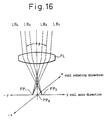
- the laser beams LB1 and LB2 , and LB3 and LB4 are made incident on the bending mirrors BM5 and BM6 as the parallel beams LB12 and LB34 , respectively, and then as shown in Figure 16, the angle ⁇ formed between the merged beams is made ⁇ ⁇ 0° by controlling the beams angles ⁇ 5 and ⁇ 6 at the above bending mirrors BM5 and BM6.
- the focusing points of the parallel beams LB 1,2 and LB 3,4 are displaced to FP1 and FP2 , respectively, from point FP0 (this point is suitable as the focal position at which the laser beam LB is made incident straight into the lens FL in embodiment 1.) where all the laser beams are parallel to one another.
- X and -X indicate a roll rotating direction
- Y and -Y indicate a roll axial direction.
- Figure 15 shows the embodiment in which four laser beams are used, but the number of laser beams is not limited thereto and may be more or less. If the number of laser beams is increased, the depth of the hole worked is nearly linearly increased, and holes having a different diameter from one another can be formed according to the number of laser beams. Therefore, the number of laser beams is selected according to the required surface roughness of a roll to be dulled.
- Figure 17 shows a functional time chart of the control signals of Figure 16.
- one dulling is effected by the laser beams LB1 and LB2
- the other dulling is effected by the laser beams LB3 and LB4.
- the Q-switching control signal Q1 is made closer to Q2 and Q3 is made closer to Q4 , and thus the Q-switch control time delays ⁇ 1 and ⁇ 3 are shortened and therefore, a dulling effect is doubled.
- a space between the pulsed laser beams LB 1,2 and LB 3,4 can be set at ⁇ 2 , and thus a space of a crater at a dulling is determined.
- This embodiment can operate at double the dulling speed of the first embodiment by using ⁇ 2 in about half of the dulling period thereof.
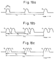
- Figures 18a, 18b, and 18c show the generation of the pulse beam group, wherein Figure 18a shows a pulse train from one Q-switched laser and Figures 18b and 18c show the pulse trains of this embodiment, respectively, which are generated by the control signal shown in Figure 17.
- Figure 18c shows the pulse train when OM1 and OM3 are set at a shorter time than the width W p of the pulse laser.
- the pulse beams of four Q-switched lasers are controlled according to this second embodiment to dull the surface under the following conditions: LB1 - LB4: 2 kW f0: 20 kHz T m : 50 »s ⁇ 1 , ⁇ 3 , ⁇ 4: 2 »s ⁇ 2: 23 »s FL: 25 mm FP1 , FP2: 50 »m ⁇ 1 , ⁇ 2: 3 mrad ⁇ 3 , ⁇ 4: 2 mrad Roll diameter: 500 mm Roll speed: 300 to 500 rpm RF output: 40%
- W x shows the space between the n number of trains : N n and the n+1 number of trains : N n+1 when one of the trains of uneven dulling is formed by rotating a roll.
- a beam splitter BS is used instead of the mirror TM of the first embodiment, and coaxially merges the pulse laser beam group.
- the "beam splitter” referred to herein is an optical element used to separate a light beam of a predetermined wavelength, when incident at an inherent angle, into a reflected light beam (T) and a transmitting light beam (R).
- an optical element has a structure in which several kinds of substances having different refraction factors are laminated on a base layer of a silica or the like and, due to the characteristics of the laminated structure, the reflected light beam (T) and the transmitting light beam (R) can be polarized simultaneously, as required.
- the transmitting light beam (R) of LB1 is a polarized component (P wave ) parallel to the incident plane of LB1
- the reflected light beam (T) of LB2 is a horizontal polarized component (S wave ).
- Figure 21a shows the basic construction of the pulse laser controller using two pulses according to this embodiment, wherein OSC1 and OSC2 indicate laser oscillators, respectively, and QS1 and QS2 indicate Q-switches, respectively, corresponding to the laser oscillators OSC1 and OSC2 , respectively.
- Reference numeral 10 indicates a Q-switching control system which delivers Q-switched signals Q1 and Q2 sequentially, and laser beams LB1 and LB2 are generated from the laser oscillators OSC1 and OSC2 correspondingly.
- the laser beam LB2 is supplied directly and LB1 is supplied through a bending mirror BM1 to the beam splitter BS, so that a transmitted beam LB1 (T) of the laser beam LB1 and the reflected beam LB2 (R) of the LB2 are merged into a group LBP1 of coaxial laser beams.
- the transmitted beam LB (T) of LB2 and reflected beam LB1 (R) are merged in another direction of the beam splitter BS into a group of coaxial laser beams LBP2.
- the laser beam groups LBP1 and LBP2 are focused by focusing lenses FL1 and FL2 , respectively, and at the focusing points FP1 and FP2 , are focused as laser beam groups LBP1 and LBP2 into a single laser beam, thereby permitting a rapid two-divisional dulling of the roll surface.
- Reference numeral 20 indicates the surface of a roll to be dulled. With the two laser beams, the depth of the hole is nearly double and a number of laser beams is selected according to the required quality of the surface roughness of a roll to be dulled.
- the frequency f0 of the pulse group for dulling the roll surface is set at the pulse generator PG and a group of pulses having a predetermined time delay therebetween is generated synchronously with the first signal of the frequency, whereby LB1 and LB2 can be controlled by Q-switching. By nulling the pulse separations ⁇ 1, both pulses also can be projected simultaneously.
- Figures 22a and 22b show the merging of laser beams, wherein Figure 22a shows a laser beam being merged by the beam splitter in which, by setting the incident angles B1 and B2 of the input lasr beams LB1 and LB2 to the same value within the inherent incident angle of the beam splitter BS, the P wave of LB1 and S wave of LB2 can be merged into a coaxial beam LBP, and Figure 22b shows a laser beam being merged by the combining mirror TM as in the first embodiment.
- the input laser beams LB1 and LB2 can be merged into parallel but not coaxial beams, and therefore, the diameter of the merged beam LBP is enlarged.
- laser beams is not limited to the surface of a roll, but can be applied to any workpiece.
- the kinds of laser used in this dulling are solid laser such as YAG, ruby lasers, etc.
- the pulse waveforms of the two Q-switched lasers were controlled by this embodiment to dull the surface of a roll, and the Q-switched laser pulse waveforms were controlled under the following conditions; Beam splitter: 650.8 mm in diameter Laser beam ⁇ 0: 300 nsec ⁇ 1: 5 » sec f0: 20 kHz Lens focal length FL: 25 mm Roll shape, length: 1500 mm diameter: 600 mm Rf, output: 40% Work time: about 1 hour
- the results were as follows: The work time was about 1 hour, which obtained the same effect as obtained using two examples of the first embodiment, the inside diameter of the hole formed by dulling was 100 »m and the roughness was 2.2 »m, the transfer to the surface of a steel sheet was as high as 80%, and the abrasion resistance was improved.
- the pulse laser beams can be merged coaxially, so that the focusing system using a lens can be made compact and simple and the positioning at the focusing point simplified. Since peak values can be set for individual pulses in the pulse group, it is possible to control the fusing and evaporation of the material from the hole being made in the dulling process, thereby permitting holes of an appropriate hardness to be formed. Further, since the separation of one pulse group from another can be controlled, crater formation or drilling further suitable for dulling can be effectively carried out.
- the Q-switched pulse waveform of the continuous excitation solid laser to a condition desired for the roll dulling, and to set a convergent beam diameter, a peak value, irradiation time and irradiated state, etc., of each pulse in the pulse group, and therefore fusing and evaporation of an irradiated article can be controlled. Accordingly, a crater of a proper hardness can be formed and the shape and position of the crater can be controlled, with the result that it is possible to obtain an arrangement of the crater which is suitable for dulling.
Abstract
Claims (3)
- Appareil pour le matage de rouleaux par un faisceau laser à impulsions, l'appareil comprenant:- plusieurs oscillateurs laser à impulsions (OSC1 - OSC4), comportant chacun un résonateur laser, un élément (2) de commutation du facteur de qualité et une source (5) de signal à fréquence radio, pour générer des faisceaux laser à impulsions respectifs (LB1 - LB4) par commutation du facteur de qualité; et- un système de contrôle (10) de la commutation du facteur de qualité, agencé pour définir la puissance de sortie desdites sources de signal à fréquence radio, ledit système de contrôle de la commutation du facteur de qualité comportant un oscillateur à impulsions (PG) en vue de déterminer une fréquence de répétition (f₀) des groupes d'impulsions, et plusieurs multivibrateurs monostables (OM₁ - OM₄) activés par ledit oscillateur à impulsions (PG) en vue d'établir une temporisation dans la puissance de sortie desdits plusieurs oscillateurs laser à impulsions (OSC1 - OSC4); ledit système de contrôle (10) de la commutation du facteur de qualité contrôlant lesdites plusieurs sources de signal à fréquence radio, de telle sorte que lesdits plusieurs oscillateurs laser (OSC1 - OSC4) soient commutés en facteur de qualité par les signaux (FR) provenant des sources à fréquence radio, pour produire un groupe d'impulsions à une fréquence (f₀), avec une temporisation prédéterminée entre chaque impulsion, et les faisceaux laser à impulsions étant dirigés vers au moins un point de traitement.
- Appareil selon la revendication 1, caractérisé en ce que des dispositifs respectifs d'expansion de faisceaux laser (BX1 - BX4) sont prévus entre les oscillateurs laser (OSC1 - OSC4) et des miroirs respectifs (BM1 - BM4) qui concentrent les faisceaux laser agrandis (LB1 - LB4) provenant des dispositifs d'expansion de faisceaux, en un groupe (LBP) de faisceaux laser parallèles ou non parallèles.
- Appareil selon la revendication 1, caractérisé en ce qu'il comporte un diviseur de faisceau (BS) qui reçoit les faisceaux laser (LB1, LB2) d'au moins deux des oscillateurs laser (OSC1, OSC2) le diviseur de faisceau (BS) séparant chaque faisceau en deux composantes (LB1(T), LB2(R); LB1(R), LB2(T)), et rassemblant ensuite coaxialement les composantes de faisceau en des groupes respectifs (LBP1, LBP2) de faisceaux laser.
Applications Claiming Priority (11)
| Application Number | Priority Date | Filing Date | Title |
|---|---|---|---|
| JP62040777A JPS63207484A (ja) | 1987-02-24 | 1987-02-24 | ロ−ルダル加工に適したqスイツチパルスレ−ザのパルス波形制御法 |
| JP40778/87 | 1987-02-24 | ||
| JP40777/87 | 1987-02-24 | ||
| JP62040778A JPS63207485A (ja) | 1987-02-24 | 1987-02-24 | 複数qスイツチレ−ザによるダルロ−ル加工に適したパルスレ−ザ制御方法 |
| JP62059860A JPS63224886A (ja) | 1987-03-14 | 1987-03-14 | レ−ザによるダルロ−ル加工方法および装置 |
| JP59860/87 | 1987-03-14 | ||
| JP313620/87 | 1987-12-11 | ||
| JP31362087 | 1987-12-11 | ||
| JP22038/88 | 1988-02-03 | ||
| JP63022038A JPH01254392A (ja) | 1987-12-11 | 1988-02-03 | 製品表面のダル加工法 |
| PCT/JP1988/000194 WO1988006504A1 (fr) | 1987-02-24 | 1988-02-24 | Procede et installation de finition mate de cylindres a l'aide d'un laser pulse |
Publications (3)
| Publication Number | Publication Date |
|---|---|
| EP0308512A1 EP0308512A1 (fr) | 1989-03-29 |
| EP0308512A4 EP0308512A4 (fr) | 1990-06-26 |
| EP0308512B1 true EP0308512B1 (fr) | 1994-06-22 |
Family
ID=27520404
Family Applications (1)
| Application Number | Title | Priority Date | Filing Date |
|---|---|---|---|
| EP88902201A Expired - Lifetime EP0308512B1 (fr) | 1987-02-24 | 1988-02-24 | Appareil pour le matage de rouleaux par un faisceau laser a impulsions |
Country Status (4)
| Country | Link |
|---|---|
| US (1) | US4947023A (fr) |
| EP (1) | EP0308512B1 (fr) |
| DE (1) | DE3850330T2 (fr) |
| WO (1) | WO1988006504A1 (fr) |
Families Citing this family (32)
| Publication number | Priority date | Publication date | Assignee | Title |
|---|---|---|---|---|
| JPH0651913B2 (ja) * | 1988-04-22 | 1994-07-06 | 川崎製鉄株式会社 | 圧延用ロールの表面加工方法及びその装置並びに該方法により製造されるプレス加工用金属薄板とその製造方法 |
| US5351399A (en) * | 1989-08-03 | 1994-10-04 | Schwabische Huttenwerke Gmbh | Method for forming grooves in roll surfaces |
| DE4033166A1 (de) * | 1990-10-19 | 1992-04-23 | Bergmann Hans Wilhelm | Verfahren zur einkopplung von cw-co(pfeil abwaerts)2(pfeil abwaerts)-laserstrahlen |
| WO1992011960A1 (fr) * | 1991-01-11 | 1992-07-23 | Nippon Steel Corporation | Cylindre refroidisseur utilise pour couler une piece mince, dispositif et procede pour former des creux sur la surface peripherique dudit cylindre |
| US5250364A (en) * | 1992-02-03 | 1993-10-05 | Aluminum Company Of America | Rolled product with textured surface for improved lubrication, formability and brightness |
| US5390204A (en) * | 1992-09-25 | 1995-02-14 | Incisive Technologies, Inc. | Intracavity modulated pulsed laser with a variably controllable modulation frequency |
| WO1994029069A1 (fr) | 1993-06-04 | 1994-12-22 | Seiko Epson Corporation | Appareil et procede d'usinage au laser, et panneau a cristaux liquides |
| US5562840A (en) * | 1995-01-23 | 1996-10-08 | Xerox Corporation | Substrate reclaim method |
| CH689917A5 (de) * | 1995-05-03 | 2000-01-31 | Daetwyler Ag | Verfahren und Vorrichtung zur Herstellung von Rasternäpfchen in der Oberfläche eines Tiefdruckzylinders. |
| FR2737814B1 (fr) * | 1995-08-11 | 1997-09-12 | Soc D Production Et De Rech Ap | Procede et dispositif de commande d'une source laser a plusieurs modules laser pour optimiser le traitement de surface par laser |
| DE19544502C1 (de) * | 1995-11-29 | 1997-05-15 | Baasel Scheel Lasergraphics Gm | Lasergravuranlage |
| JP3517082B2 (ja) * | 1997-05-26 | 2004-04-05 | 日本たばこ産業株式会社 | 帯状材の開孔装置 |
| JP3514129B2 (ja) * | 1998-07-22 | 2004-03-31 | スズキ株式会社 | レーザ加工装置 |
| CA2370832A1 (fr) * | 1999-04-27 | 2000-11-02 | Gsi Lumonics Inc. | Systeme et procede de traitement de materiaux a l'aide de faisceaux laser multiples |
| EP1068923B1 (fr) * | 1999-07-12 | 2007-10-17 | MDC Max Dätwyler AG Bleienbach | Procédé pour obtenir une répartition d'intensité sur un faisceau laser de travail ainsi qu'un appareil pour celà |
| DE10006516C2 (de) * | 2000-02-15 | 2002-01-10 | Datacard Corp | Verfahren zum Bearbeiten von Werkstücken mittels mehrerer Laserstrahlen |
| JP3421633B2 (ja) | 2000-04-11 | 2003-06-30 | ファナック株式会社 | レーザ加工装置 |
| JP3838064B2 (ja) * | 2001-09-28 | 2006-10-25 | 松下電器産業株式会社 | レーザ制御方法 |
| AU2002348254A1 (en) * | 2001-11-30 | 2003-06-17 | Matsushita Electric Industrial Co., Ltd. | Method of laser milling using constant tool path algorithm |
| US6998567B2 (en) * | 2003-01-31 | 2006-02-14 | Trimedyne, Inc. | Generation and application of efficient solid-state laser pulse trains |
| US7265772B2 (en) * | 2004-12-16 | 2007-09-04 | Esko Graphics A/S | Beam illumination system and method for producing printing plates |
| US7947207B2 (en) | 2005-04-12 | 2011-05-24 | Abbott Cardiovascular Systems Inc. | Method for retaining a vascular stent on a catheter |
| US20080018943A1 (en) * | 2006-06-19 | 2008-01-24 | Eastman Kodak Company | Direct engraving of flexographic printing plates |
| US7807938B2 (en) * | 2006-06-22 | 2010-10-05 | Sabic Innovative Plastics Ip B.V. | Mastering tools and systems and methods for forming a plurality of cells on the mastering tools |
| US8262381B2 (en) * | 2006-06-22 | 2012-09-11 | Sabic Innovative Plastics Ip B.V. | Mastering tools and systems and methods for forming a cell on the mastering tools |
| DE102007032903A1 (de) * | 2007-07-14 | 2009-01-15 | Schepers Gmbh + Co. Kg | Verfahren zum Betreiben einer Lasergravureinrichtung |
| DE102011121545B4 (de) * | 2011-12-20 | 2013-07-11 | Eads Deutschland Gmbh | Verfahren zur Strukturierung und chemischen Modifikation einer Oberfläche eines Werkstücks |
| DE102011121546B4 (de) * | 2011-12-20 | 2013-07-11 | Eads Deutschland Gmbh | Verfahren zur Strukturierung einer Oberfläche eines Werkstücks |
| ITMI20112330A1 (it) * | 2011-12-21 | 2013-06-22 | Tenova Spa | Macchina operatrice e relativo metodo per il trattamento superficiale di cilindri |
| DE102012019917A1 (de) * | 2012-10-11 | 2014-02-06 | Eads Deutschland Gmbh | Verfahren zur Nanostrukturierung polymerer Materialien mit gepulster Laserstrahlung in inerter Atmosphäre |
| DE102012019919A1 (de) * | 2012-10-11 | 2014-02-06 | Eads Deutschland Gmbh | Verfahren zur Nanostrukturierung polymerer Materialien mit gepulster Laserstrahlung in reaktiver Atmosphäre |
| DE102014110285A1 (de) * | 2014-07-22 | 2016-01-28 | Thyssenkrupp Ag | Einrichtung und Verfahren zum Strukturieren einer Walze durch Laserabtrag |
Family Cites Families (5)
| Publication number | Priority date | Publication date | Assignee | Title |
|---|---|---|---|---|
| US3404254A (en) * | 1965-02-26 | 1968-10-01 | Minnesota Mining & Mfg | Method and apparatus for engraving a generally cross-sectionally circular shaped body by a corpuscular beam |
| CH296869A4 (fr) * | 1969-02-27 | 1970-06-30 | ||
| GB1540064A (en) * | 1975-07-08 | 1979-02-07 | Atomic Energy Authority Uk | Laser removal of material from workpieces |
| JPS5879788A (ja) * | 1981-11-06 | 1983-05-13 | Nec Corp | Qスイツチレ−ザ装置の駆動方法 |
| US4675872A (en) * | 1985-09-30 | 1987-06-23 | Harris Corporation | Driver unit for a laser Q-switch |
-
1988
- 1988-02-24 EP EP88902201A patent/EP0308512B1/fr not_active Expired - Lifetime
- 1988-02-24 WO PCT/JP1988/000194 patent/WO1988006504A1/fr active IP Right Grant
- 1988-02-24 DE DE3850330T patent/DE3850330T2/de not_active Expired - Fee Related
- 1988-10-18 US US07/305,121 patent/US4947023A/en not_active Expired - Fee Related
Also Published As
| Publication number | Publication date |
|---|---|
| DE3850330T2 (de) | 1994-10-13 |
| WO1988006504A1 (fr) | 1988-09-07 |
| DE3850330D1 (de) | 1994-07-28 |
| US4947023A (en) | 1990-08-07 |
| EP0308512A1 (fr) | 1989-03-29 |
| EP0308512A4 (fr) | 1990-06-26 |
Similar Documents
| Publication | Publication Date | Title |
|---|---|---|
| EP0308512B1 (fr) | Appareil pour le matage de rouleaux par un faisceau laser a impulsions | |
| US8208506B2 (en) | Methods and systems for generating pulse trains for material processing | |
| AU781106B2 (en) | Method for the machining of workpieces by means of several laser beams | |
| GB1576460A (en) | Method of and apparatus for machining a predetermined pattern of discrete areas on an object | |
| JP3122668B2 (ja) | グラビア印刷シリンダの表面にグリッド階段を作る方法及び装置 | |
| CN109570781A (zh) | 一种微孔阵列加工装置及方法 | |
| JP2001105166A (ja) | 作業レーザビームにわたって強度分布を発生する方法及びそのための装置 | |
| WO2001051244A1 (fr) | Appareil et procede de ciblage | |
| KR101609657B1 (ko) | 작업물을 파괴 분할하기 위한 방법, 작업물 및 레이저 유닛 | |
| KR100371125B1 (ko) | 저가의 평균 전력과 휘도가 높은 고상 펄스 레이저 시스템 | |
| JP3463281B2 (ja) | 多軸レーザ加工装置及びレーザ加工方法 | |
| JP2919037B2 (ja) | レーザパターン形成装置 | |
| JP2002239772A (ja) | レーザ加工方法およびその装置 | |
| JPH0790385A (ja) | 磁気特性の優れた方向性電磁鋼板 | |
| JPH0440118B2 (fr) | ||
| JP2000292819A (ja) | 波長変換方法 | |
| JPH03180286A (ja) | レーザ加工方法 | |
| JPH04253588A (ja) | 金属表面のレーザー加工方法 | |
| JP2002252402A (ja) | レーザ発振器およびそのレーザパルス制御方法 | |
| JPS602156B2 (ja) | ロ−ルの粗面化装置 | |
| CN114401812B (zh) | 用于对工件进行激光加工的加工设备、用于对工件进行激光加工的方法 | |
| JPH0327313B2 (fr) | ||
| JPS63224886A (ja) | レ−ザによるダルロ−ル加工方法および装置 | |
| JPH04253583A (ja) | 金属表面のレーザー加工方法 | |
| KR20220128297A (ko) | 프린트 기판의 레이저 가공 방법 및 프린트 기판의 레이저 가공기 |
Legal Events
| Date | Code | Title | Description |
|---|---|---|---|
| PUAI | Public reference made under article 153(3) epc to a published international application that has entered the european phase |
Free format text: ORIGINAL CODE: 0009012 |
|
| 17P | Request for examination filed |
Effective date: 19881021 |
|
| AK | Designated contracting states |
Kind code of ref document: A1 Designated state(s): BE DE GB IT |
|
| A4 | Supplementary search report drawn up and despatched |
Effective date: 19900626 |
|
| 17Q | First examination report despatched |
Effective date: 19910506 |
|
| GRAA | (expected) grant |
Free format text: ORIGINAL CODE: 0009210 |
|
| AK | Designated contracting states |
Kind code of ref document: B1 Designated state(s): BE DE GB IT |
|
| REF | Corresponds to: |
Ref document number: 3850330 Country of ref document: DE Date of ref document: 19940728 |
|
| ITF | It: translation for a ep patent filed |
Owner name: STUDIO TORTA SOCIETA' SEMPLICE |
|
| PLBE | No opposition filed within time limit |
Free format text: ORIGINAL CODE: 0009261 |
|
| STAA | Information on the status of an ep patent application or granted ep patent |
Free format text: STATUS: NO OPPOSITION FILED WITHIN TIME LIMIT |
|
| 26N | No opposition filed | ||
| PGFP | Annual fee paid to national office [announced via postgrant information from national office to epo] |
Ref country code: GB Payment date: 19970217 Year of fee payment: 10 |
|
| PGFP | Annual fee paid to national office [announced via postgrant information from national office to epo] |
Ref country code: DE Payment date: 19970228 Year of fee payment: 10 |
|
| PGFP | Annual fee paid to national office [announced via postgrant information from national office to epo] |
Ref country code: BE Payment date: 19970410 Year of fee payment: 10 |
|
| PG25 | Lapsed in a contracting state [announced via postgrant information from national office to epo] |
Ref country code: GB Free format text: LAPSE BECAUSE OF NON-PAYMENT OF DUE FEES Effective date: 19980224 |
|
| PG25 | Lapsed in a contracting state [announced via postgrant information from national office to epo] |
Ref country code: BE Free format text: LAPSE BECAUSE OF NON-PAYMENT OF DUE FEES Effective date: 19980228 |
|
| BERE | Be: lapsed |
Owner name: NIPPON STEEL CORP. Effective date: 19980228 |
|
| GBPC | Gb: european patent ceased through non-payment of renewal fee |
Effective date: 19980224 |
|
| PG25 | Lapsed in a contracting state [announced via postgrant information from national office to epo] |
Ref country code: DE Free format text: LAPSE BECAUSE OF NON-PAYMENT OF DUE FEES Effective date: 19981103 |
|
| PG25 | Lapsed in a contracting state [announced via postgrant information from national office to epo] |
Ref country code: IT Free format text: LAPSE BECAUSE OF NON-PAYMENT OF DUE FEES;WARNING: LAPSES OF ITALIAN PATENTS WITH EFFECTIVE DATE BEFORE 2007 MAY HAVE OCCURRED AT ANY TIME BEFORE 2007. THE CORRECT EFFECTIVE DATE MAY BE DIFFERENT FROM THE ONE RECORDED. Effective date: 20050224 |