EP0307317A2 - Vehicle window - Google Patents
Vehicle window Download PDFInfo
- Publication number
- EP0307317A2 EP0307317A2 EP88402266A EP88402266A EP0307317A2 EP 0307317 A2 EP0307317 A2 EP 0307317A2 EP 88402266 A EP88402266 A EP 88402266A EP 88402266 A EP88402266 A EP 88402266A EP 0307317 A2 EP0307317 A2 EP 0307317A2
- Authority
- EP
- European Patent Office
- Prior art keywords
- glazing
- wing
- profile
- vehicle window
- edge
- Prior art date
- Legal status (The legal status is an assumption and is not a legal conclusion. Google has not performed a legal analysis and makes no representation as to the accuracy of the status listed.)
- Granted
Links
- 239000003292 glue Substances 0.000 claims abstract description 10
- 239000000853 adhesive Substances 0.000 claims description 14
- 230000001070 adhesive effect Effects 0.000 claims description 14
- 239000011324 bead Substances 0.000 claims description 13
- 229920003023 plastic Polymers 0.000 claims description 10
- 239000004033 plastic Substances 0.000 claims description 10
- 238000001125 extrusion Methods 0.000 claims description 7
- 239000002184 metal Substances 0.000 claims description 6
- 230000002093 peripheral effect Effects 0.000 claims description 4
- 239000011521 glass Substances 0.000 claims description 3
- 230000002787 reinforcement Effects 0.000 claims description 3
- 230000005489 elastic deformation Effects 0.000 claims 1
- 241001074085 Scophthalmus aquosus Species 0.000 abstract 1
- 238000000034 method Methods 0.000 description 6
- 238000000151 deposition Methods 0.000 description 3
- 230000000694 effects Effects 0.000 description 2
- 239000000463 material Substances 0.000 description 2
- 229920002635 polyurethane Polymers 0.000 description 2
- 239000004814 polyurethane Substances 0.000 description 2
- 229920001730 Moisture cure polyurethane Polymers 0.000 description 1
- 238000004026 adhesive bonding Methods 0.000 description 1
- 230000000295 complement effect Effects 0.000 description 1
- 210000003298 dental enamel Anatomy 0.000 description 1
- 230000008021 deposition Effects 0.000 description 1
- 229920001971 elastomer Polymers 0.000 description 1
- 239000000806 elastomer Substances 0.000 description 1
- 238000009434 installation Methods 0.000 description 1
- 230000003993 interaction Effects 0.000 description 1
- 230000002045 lasting effect Effects 0.000 description 1
- 239000003973 paint Substances 0.000 description 1
- 235000011837 pasties Nutrition 0.000 description 1
- 230000035515 penetration Effects 0.000 description 1
- 238000003466 welding Methods 0.000 description 1
Images


Classifications
-
- B—PERFORMING OPERATIONS; TRANSPORTING
- B60—VEHICLES IN GENERAL
- B60J—WINDOWS, WINDSCREENS, NON-FIXED ROOFS, DOORS, OR SIMILAR DEVICES FOR VEHICLES; REMOVABLE EXTERNAL PROTECTIVE COVERINGS SPECIALLY ADAPTED FOR VEHICLES
- B60J1/00—Windows; Windscreens; Accessories therefor
-
- B—PERFORMING OPERATIONS; TRANSPORTING
- B32—LAYERED PRODUCTS
- B32B—LAYERED PRODUCTS, i.e. PRODUCTS BUILT-UP OF STRATA OF FLAT OR NON-FLAT, e.g. CELLULAR OR HONEYCOMB, FORM
- B32B17/00—Layered products essentially comprising sheet glass, or glass, slag, or like fibres
- B32B17/06—Layered products essentially comprising sheet glass, or glass, slag, or like fibres comprising glass as the main or only constituent of a layer, next to another layer of a specific material
- B32B17/10—Layered products essentially comprising sheet glass, or glass, slag, or like fibres comprising glass as the main or only constituent of a layer, next to another layer of a specific material of synthetic resin
- B32B17/10005—Layered products essentially comprising sheet glass, or glass, slag, or like fibres comprising glass as the main or only constituent of a layer, next to another layer of a specific material of synthetic resin laminated safety glass or glazing
- B32B17/10009—Layered products essentially comprising sheet glass, or glass, slag, or like fibres comprising glass as the main or only constituent of a layer, next to another layer of a specific material of synthetic resin laminated safety glass or glazing characterized by the number, the constitution or treatment of glass sheets
- B32B17/10036—Layered products essentially comprising sheet glass, or glass, slag, or like fibres comprising glass as the main or only constituent of a layer, next to another layer of a specific material of synthetic resin laminated safety glass or glazing characterized by the number, the constitution or treatment of glass sheets comprising two outer glass sheets
-
- B—PERFORMING OPERATIONS; TRANSPORTING
- B32—LAYERED PRODUCTS
- B32B—LAYERED PRODUCTS, i.e. PRODUCTS BUILT-UP OF STRATA OF FLAT OR NON-FLAT, e.g. CELLULAR OR HONEYCOMB, FORM
- B32B17/00—Layered products essentially comprising sheet glass, or glass, slag, or like fibres
- B32B17/06—Layered products essentially comprising sheet glass, or glass, slag, or like fibres comprising glass as the main or only constituent of a layer, next to another layer of a specific material
- B32B17/10—Layered products essentially comprising sheet glass, or glass, slag, or like fibres comprising glass as the main or only constituent of a layer, next to another layer of a specific material of synthetic resin
- B32B17/10005—Layered products essentially comprising sheet glass, or glass, slag, or like fibres comprising glass as the main or only constituent of a layer, next to another layer of a specific material of synthetic resin laminated safety glass or glazing
- B32B17/10165—Functional features of the laminated safety glass or glazing
- B32B17/10293—Edge features, e.g. inserts or holes
-
- B—PERFORMING OPERATIONS; TRANSPORTING
- B60—VEHICLES IN GENERAL
- B60J—WINDOWS, WINDSCREENS, NON-FIXED ROOFS, DOORS, OR SIMILAR DEVICES FOR VEHICLES; REMOVABLE EXTERNAL PROTECTIVE COVERINGS SPECIALLY ADAPTED FOR VEHICLES
- B60J1/00—Windows; Windscreens; Accessories therefor
- B60J1/08—Windows; Windscreens; Accessories therefor arranged at vehicle sides
- B60J1/10—Windows; Windscreens; Accessories therefor arranged at vehicle sides fixedly mounted
-
- B—PERFORMING OPERATIONS; TRANSPORTING
- B60—VEHICLES IN GENERAL
- B60J—WINDOWS, WINDSCREENS, NON-FIXED ROOFS, DOORS, OR SIMILAR DEVICES FOR VEHICLES; REMOVABLE EXTERNAL PROTECTIVE COVERINGS SPECIALLY ADAPTED FOR VEHICLES
- B60J10/00—Sealing arrangements
- B60J10/30—Sealing arrangements characterised by the fastening means
-
- B—PERFORMING OPERATIONS; TRANSPORTING
- B60—VEHICLES IN GENERAL
- B60J—WINDOWS, WINDSCREENS, NON-FIXED ROOFS, DOORS, OR SIMILAR DEVICES FOR VEHICLES; REMOVABLE EXTERNAL PROTECTIVE COVERINGS SPECIALLY ADAPTED FOR VEHICLES
- B60J10/00—Sealing arrangements
- B60J10/70—Sealing arrangements specially adapted for windows or windscreens
-
- B—PERFORMING OPERATIONS; TRANSPORTING
- B61—RAILWAYS
- B61D—BODY DETAILS OR KINDS OF RAILWAY VEHICLES
- B61D25/00—Window arrangements peculiar to rail vehicles
Definitions
- the invention relates to a vehicle window comprising on the one hand a metal sheet of peripheral holding parallel to the glazing to which the glazing is glued using a bead of adhesive and on the other hand a glazing fitted with either a plastic frame or a plastic profile bonded to its periphery, the frame or profile being provided with at least one wing perpendicular to the surface of the glazing.
- Automotive glazing intended for direct bonding is generally fitted on their surface directed towards the sheet for holding an opaque deposit of light and ultraviolet rays in the form of a frame which is generally made up of a hot paint or a E-mail.
- This deposit serves on the one hand to protect the adhesive bead from the action of ultraviolet rays and on the other hand prevents it from being visible from the outside, through the glazing.
- automobile glazing is also used for direct bonding which, instead of or in addition to the frame-shaped deposit, has a plastic frame or a profile also made of plastic placed in advance at the periphery of the glazing.
- plastic frame or a profile also made of plastic placed in advance at the periphery of the glazing.
- thermal bonding there are also known glazings fitted at their periphery with a plastic frame or a plastic profile having a wing directed towards the retaining plate and perpendicular to the surface of the glazing (see for example EP 121 481 B).
- This wing is always located at the limit of the frame or the profile towards the inside of the windshield and it thus serves to limit the lateral overflow of the adhesive mass during the installation of the glazing equipped with its adhesive bead.
- the glazing With direct bonding, the glazing must be positioned precisely in relation to the rebate of the bay the body. It is indeed necessary that the space remaining between the edge of the glazing and the edge of the rebate has a constant width. The minimum requirement imposed is to have an upper horizontal groove which has a constant given width. Indeed, in many cases, the lower edge of the glazing both of the windshield and of the rear window is hidden by bodywork elements and only the upper groove is visible.
- the glazing In direct bonding, the glazing must be mechanically held in the opening until the bead of glue is hard enough not to deform under the effect of the weight of the glazing. If it were otherwise, the glazing would move under the effect of its weight and the upper horizontal groove would exceed acceptable tolerances.
- the invention sets itself the task of finding a labor-saving solution for positioning and fixing automotive glazing intended for direct bonding.
- This solution must at least guarantee that the upper and / or lower horizontal groove between the edge of the glazing and the edge of the rebate has a defined width and that the glazing is immobilized in the corresponding position.
- this mission is carried out by positioning the frame or profile wing along the upper and / or lower edge of the glazing, at a given constant distance from the edge of the rebate of the opening and by providing it with a bearing surface intended to support the component of the weight of the glazing directed in the plane of the opening, said bearing surface, cooperating with the bearing element of the upper and / or lower retaining plate directed substantially perpendicularly to the plan of the bay so as to constitute an assembly.
- the profile rigidly connected to the edge of the glazing has been given a wing shape known per se, and on the one hand, specific dimensions as well as a section of determined shape such that it can on its own exercise the support function and that no accessory element is necessary.
- the wing of this profile is not positioned relative to the edge of the glazing but on the contrary, deliberately, with reference to the rebate of the opening which faces it with respect to which it remains at a determined distance.
- this section equipped with its wing makes it possible to position the glazing relative to the upper and / or lower horizontal part of the opening.
- the rebate plays directly or indirectly the role of support for the wing of the profile. A device is thus produced which makes it possible to position and fix the glazing in a particularly simple and effective manner and using minimal labor.
- the glazing is only equipped with the profile provided with its wing allowing the positioning and fixing of the glazing only along its upper or lower edge.
- the glazing is suspended so to speak in the opening, that is to say that it is first the profile wing which comes in contact with the support surface of the rebate.
- the glazing adjusts symmetrically in the opening, that is to say that it is moved laterally until the two peripheral grooves have the same width.
- the glazing over its entire periphery which is applied to the retaining plate.
- the weight component of the glazing which acts by applying it to the retaining plate is generally sufficient, given the usual inclination of the glazing, to allow it to exert sufficient pressure so as to crush the bead glue on the retaining plate.
- the profile equipped with its wing is also placed along the side edges of the glazing, the lateral sections of the profile are used here to automatically adjust the position of the glazing laterally.
- the wings of the profile are dimensioned and placed so that they can bear on a rebate part perpendicular to the retaining plate, for example at the periphery of the rebate.
- the lateral wing of the profile must be arranged in such a way that it can be supported in the rebate without any play.
- the lateral wings of the profile are endowed with an elasticity such as when the glazing is placed in the bay, they can deform elastically laterally.
- the peripheral profile is fitted with shims or notches which will, during assembly, cooperate with complementary notches or shims placed on the retaining plate to create continuity between the glazing and the bodywork .
- these shims or these notches must have been placed in relation to the body part which surrounds the opening so that, when the shims are assembled in the notches, the whole design is obtained continuity between the external surfaces of the glazing and the bodywork.
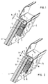
- FIGS 1 to 8 show a series of embodiments of a rack according to the invention.
- a section of the glazing and its environment is presented in the upper or lower part of the horizontal periphery of the bay.
- these are glazings fitted by bonding on their internal surface, that is to say on the surface opposite to the retaining plate, with a plastic profile. It can be a preformed profile which is glued as it is to the surface of the glazing as described for example in patent application DE-35 36 806.
- a particularly advantageous way is to create the profile simultaneously with depositing it by extruding it using a nozzle with a suitable section, directly on the surface of the glazing.
- the material is an adhesive mass which hardens.
- This extrusion technique and the corresponding adhesive masses are known.
- the most suitable materials for such extrusion are the one-component polyurethane prepolymers in pasty form.
- the profile on the glazing it is possible, for example, to use an extrusion head which is driven along the edge of the glazing at a defined distance. This can be achieved using a device mechanical which keeps the distance to the edge of the glazing constant.
- the conduct of the extrusion head along the periphery of the glazing can however be carried out using a robot programmed accordingly or another programmable machine without the need to place oneself directly in reference by relation to the edge of the glazing.
- the latter method has the advantage that the deposition of the profile on the glazing is independent of the edge of the latter and that consequently it may depend only on the shape and dimensions of the opening and on its own design. Thus, for example, the distance between the profile and the horizontal upper edge of the glazing may be different from what it is on the lateral edges.
- laminated glazing has been used as is generally used in automobile windshields. It is obvious that one could use a monolithic glazing or even a glazing made of another glass / plastic combination instead of this.
- FIG. 1 shows a first embodiment of a vehicle window according to the invention.
- the glazing 1 is fitted along its border on the face opposite the retaining plate 2 with an opaque deposit 3 in the form of a frame.
- This deposit 3 consists of a hot enamel.
- the profile 4 and the sheet metal return 7 are placed in such a manner relative to the holding sheet 2 of on the one hand and to the glazing 1 on the other hand that the groove which remains between the periphery 11 of the glazing 1 and the edge 12 of the rebate of the opening has the same width over the entire width of the glazing.
- the embodiment presented in FIG. 2 consists of a section 4 placed on the glazing 1 and which has substantially the same shape and the same section as in the embodiment of Figure 1.
- the holding plate 14 consists of two unit sheets 15 and 16 which are straight.
- the bearing surface for the profile 4 is constituted by the sheet 17 which is obtained by stamping the sheet 15 on three sides then by folding.
- the opening 18 thus formed in the section of the sheet 15 is closed and sealed by the penetration of the adhesive mass 10.
- FIG 3 shows an embodiment in which the glazing 1 is equipped with a profile 20 which by its interaction with the holding plate 21 allows positioning and fixing of the glazing 1 in three dimensions.
- the profile 20 has approximately the shape of a U consisting of a central part 27, a first wing 22, external, and an internal wing, 23.
- the external wing 22 has the same shape and fills the same function as the section 4 of the embodiments previously described. It cooperates all along the upper edge of the glazing with the sheet metal element 19 which has the shape of a hook.
- this hook-shaped sheet 19 is independent, it is fixed to the holding sheet 21 by spot welding.
- the inner wing 23 of the profile 20 has a length L which is greater than the distance between the surface of the glass and the retaining plate 21.
- the wing 23 On its inner face the wing 23 is equipped with a groove 25. It is in this groove that the edge 26 of the retaining plate 21 will be fixed. Thanks to the internal wing 23, a symmetrical centering of the glazing is obtained.
- the wings 23 act as elastic springs, they therefore deform elastically during the introduction of the glazing so that the sheet 26 is introduced into the groove 25.
- the embodiment shown in Figure 4 also has a profile 28 whose section is substantially U-shaped. But this time the weight of the glazing 1 cooperates via the internal wing 29 of the profile that is -to say the lower wing with the curved end 30 of the retaining plate 21. Instead of the curved plate 30 one could also here use hook-shaped support elements which would then be fixed to the plate support 31.
- the profile 28 has outwardly a wing 32 which is approximately perpendicular to the surface of the glazing. This wing 32 which has approximately a triangular section acts as a support for the adhesive mass 10.
- FIG. 5 represents an embodiment in which the glazing 1 is equipped in a well-defined configuration with a profile 34.
- the profile 34 ends with a reinforcement 35 which is held in a channel.
- the latter is constituted by the curved ends 36 and 38 of the retaining plate 40.
- the embodiment presented in Figure 6 shows the device for positioning and fixing the glazing 1 made in a manner similar to that of the previous examples.
- the wing 34 has a reinforcement 35 which cooperates with a channel formed by deformation of the ends 36 and 38 of the retaining plate 40.
- the wing 34 is here the internal part of a profile 42 which has a U-shaped section.
- the outer wing 43 has a groove 44 into which a cord with high tensile strength can be inserted. If necessary, it can be used to shear the bead of glue 10 and the wing 34 of the profile. The use of such a cord is known and facilitates the possible dismantling of the glazing.
- Figure 7 shows in section an embodiment in the lower part of a bay.
- the section 46 placed along the lower edge of the glazing 1, serves as a rigid support linked to the glazing. It will be supported on the upper edge 47 of the retaining plate 48.
- the section 46 is here also equipped on its lower face with a groove 49 in which the upper edge 47 of the retaining plate 48 engages.
- the immobilization produced by the section 46 lasts at least as long as is necessary to obtain the hardening of the bead of adhesive 10.
- FIG. 8 shows an exemplary embodiment in which the profile 52 placed on the glazing 1 realizes its positioning in three dimensions when it is disposed over its entire periphery.
- the internal wing 53 rests again along the edge 54 of the retaining plate 55, the edge 54, then being inserted into the groove 56. In this way, precise glazing positioning is obtained in its plane.
- the outer wing 57 has a height H which corresponds to the desired distance between the glazing and the retaining plate 55. Its function consists in playing the role of stop when the glazing is installed in the opening.
- the adhesive bead 10 is then pressed through the glazing in the direction of the holding plate 55 up to the limit constituted by the wing in question. This gives precise positioning of the glazing in the direction perpendicular to its surface.
Landscapes
- Engineering & Computer Science (AREA)
- Mechanical Engineering (AREA)
- Window Of Vehicle (AREA)
- Securing Of Glass Panes Or The Like (AREA)
- Air-Conditioning For Vehicles (AREA)
- Motor Or Generator Current Collectors (AREA)
- Insulation, Fastening Of Motor, Generator Windings (AREA)
- Joining Of Glass To Other Materials (AREA)
- Aiming, Guidance, Guns With A Light Source, Armor, Camouflage, And Targets (AREA)
- Laminated Bodies (AREA)
Abstract
Description
L'invention concerne une fenêtre de véhicule comportant d'une part une tôle métallique de maintien périphérique parallèle au vitrage à laquelle le vitrage est collé à l'aide d'un cordon de colle et d'autre part un vitrage équipé soit d'un cadre en plastique soit d'un profilé plastique collé à sa périphérie, le cadre ou le profilé étant pourvu d'au moins une aile perpendiculaire à la surface du vitrage.The invention relates to a vehicle window comprising on the one hand a metal sheet of peripheral holding parallel to the glazing to which the glazing is glued using a bead of adhesive and on the other hand a glazing fitted with either a plastic frame or a plastic profile bonded to its periphery, the frame or profile being provided with at least one wing perpendicular to the surface of the glazing.
La technique de montage des vitrages automobiles qui consiste à coller sans intermédiaire le vitrage à la tôle de maintien de la baie est souvent appelée "collage direct".The technique for mounting automotive glazing, which consists of bonding the glazing without intermediary to the sheet holding the bay, is often called "direct bonding".
Les vitrages automobiles destinés au collage direct sont généralement équipés sur leur surface dirigée vers la tôle de maintien d'un dépôt opaque à la lumière et aux rayons ultraviolets en forme de cadre qui est en général constitué d'une peinture à chaud ou d'un émail. Ce dépôt sert d'une part à protéger le cordon de colle de l'action des rayons ultraviolets et évite d'autre part qu'il ne soit visible de l'extérieur, au travers du vitrage.Automotive glazing intended for direct bonding is generally fitted on their surface directed towards the sheet for holding an opaque deposit of light and ultraviolet rays in the form of a frame which is generally made up of a hot paint or a E-mail. This deposit serves on the one hand to protect the adhesive bead from the action of ultraviolet rays and on the other hand prevents it from being visible from the outside, through the glazing.
Par ailleurs, on utilise également pour le collage direct, des vitrages automobiles qui possèdent à la place du dépôt en forme de cadre ou en plus de celui-ci, un cadre en matière plastique ou un profilé également en plastique placés à l'avance à la périphérie du vitrage. Pour le collage direct on connaît également des vitrages équipés à leur périphérie d'un cadre en matière plastique ou d'un profilé en plastique possédant une aile dirigée vers la tôle de maintien et perpendiculaire à la surface du vitrage (voir par exemple EP 121 481 B). Cette aile est toujours située à la limite du cadre ou du profilé vers l'intérieur du parebrise et elle sert ainsi à limiter le débordement latéral de la masse adhésive lors de la pose du vitrage équipé de son cordon de colle.Furthermore, automobile glazing is also used for direct bonding which, instead of or in addition to the frame-shaped deposit, has a plastic frame or a profile also made of plastic placed in advance at the periphery of the glazing. For direct bonding there are also known glazings fitted at their periphery with a plastic frame or a plastic profile having a wing directed towards the retaining plate and perpendicular to the surface of the glazing (see for example EP 121 481 B). This wing is always located at the limit of the frame or the profile towards the inside of the windshield and it thus serves to limit the lateral overflow of the adhesive mass during the installation of the glazing equipped with its adhesive bead.
Avec le collage direct, il est nécessaire que les vitrages soient positionnés précisément par rapport à la feuillure de la baie de la carrosserie. Il faut en effet que l'espace restant entre le bord du vitrage et le bord de la feuillure ait une largeur constante. L'exigence minimale imposée oblige à avoir une rainure horizontale supérieure qui ait une largeur donnée constante. En effet, dans beaucoup de cas, le bord inférieur du vitrage aussi bien du parebrise que de la lunette arrière est caché par des éléments de carrosserie et seule, la rainure supérieure est visible. Dans le collage direct il faut maintenir mécaniquement le vitrage dans la baie jusqu'à ce que le cordon de colle soit suffisamment dur pour ne plus se déformer sous l'effet du poids du vitrage. S'il en était autrement, le vitrage se déplacerait sous l'effet de son poids et la rainure supérieure horizontale sortirait des tolérances acceptables.With direct bonding, the glazing must be positioned precisely in relation to the rebate of the bay the body. It is indeed necessary that the space remaining between the edge of the glazing and the edge of the rebate has a constant width. The minimum requirement imposed is to have an upper horizontal groove which has a constant given width. Indeed, in many cases, the lower edge of the glazing both of the windshield and of the rear window is hidden by bodywork elements and only the upper groove is visible. In direct bonding, the glazing must be mechanically held in the opening until the bead of glue is hard enough not to deform under the effect of the weight of the glazing. If it were otherwise, the glazing would move under the effect of its weight and the upper horizontal groove would exceed acceptable tolerances.
Pour fixer temporairement le vitrage pendant le temps de prise de la colle, plusieurs méthodes sont connues : on peut par exemple coller à la périphérie du vitrage des éclisses faites d'un métal qui se déforment plastiquement. Après collage du vitrage, ces éclisses sont rabattues dans la feuillure (EP-148 797 A). Cette méthode nécessite un positionnement précis du vitrage dans la feuillure et exige par ailleurs un travail manuel conséquent pour replier toutes les éclisses à la fin de l'opération.To temporarily fix the glazing during the setting time of the glue, several methods are known: it is for example possible to glue to the periphery of the glazing ribs made of a metal which are plastically deformed. After gluing the glazing, these ribs are folded into the rebate (EP-148,797 A). This method requires precise positioning of the glazing in the rebate and also requires considerable manual work to fold all the fishplates at the end of the operation.
L'invention se donne pour mission de trouver une solution économe en main d'oeuvre pour positionner et fixer un vitrage automobile destiné au collage direct. Cette solution doit garantir au minimum que la rainure horizontale supérieure et/ou inférieure entre le bord du vitrage et le bord de la feuillure ait une largeur définie et que le vitrage soit immobilisé dans la position correspondante.The invention sets itself the task of finding a labor-saving solution for positioning and fixing automotive glazing intended for direct bonding. This solution must at least guarantee that the upper and / or lower horizontal groove between the edge of the glazing and the edge of the rebate has a defined width and that the glazing is immobilized in the corresponding position.
Selon l'invention, on réalise cette mission en positionnant l'aile du cadre ou du profilé le long du bord supérieur et/ou inférieur du vitrage, à une distance constante donnée du bord de la feuillure de la baie et en la dotant d'une surface d'appui destinée à supporter la composante du poids du vitrage dirigée dans le plan de la baie, ladite surface d'appui, coopérant avec l'élément d'appui de la tôle de maintien supérieure et/ou inférieure dirigé sensiblement perpendiculairement au plan de la baie de manière à constituer un assemblage.According to the invention, this mission is carried out by positioning the frame or profile wing along the upper and / or lower edge of the glazing, at a given constant distance from the edge of the rebate of the opening and by providing it with a bearing surface intended to support the component of the weight of the glazing directed in the plane of the opening, said bearing surface, cooperating with the bearing element of the upper and / or lower retaining plate directed substantially perpendicularly to the plan of the bay so as to constitute an assembly.
Conformément à l'invention, on a donné au profilé lié rigidement au bord du vitrage une forme en aile connue en soi, et d'une part, des dimensions spécifiques ainsi qu'une section de forme déterminée telles qu'il puisse à lui seul exercer la fonction d'appui et qu'aucun élément accessoire ne soit nécessaire. D'un autre côté, l'aile de ce profilé ne se positionne pas par rapport au bord du vitrage mais au contraire, délibérément, en référence à la feuillure de la baie qui lui fait face par rapport à laquelle il reste à une distance déterminée. On voit qu'ainsi, à la différence des méthodes connues, ce profilé équipé de son aile permet de positionner le vitrage par rapport à la partie horizontale supérieure et/ou inférieure de la baie. De plus, selon l'invention, la feuillure joue directement ou indirectement le rôle d'appui pour l'aile du profilé. On réalise ainsi un dispositif qui permet de positionner et de fixer le vitrage de manière particulièrement simple et efficace et en employant une main d'oeuvre minimale.According to the invention, the profile rigidly connected to the edge of the glazing has been given a wing shape known per se, and on the one hand, specific dimensions as well as a section of determined shape such that it can on its own exercise the support function and that no accessory element is necessary. On the other hand, the wing of this profile is not positioned relative to the edge of the glazing but on the contrary, deliberately, with reference to the rebate of the opening which faces it with respect to which it remains at a determined distance. We see that thus, unlike the known methods, this section equipped with its wing makes it possible to position the glazing relative to the upper and / or lower horizontal part of the opening. In addition, according to the invention, the rebate plays directly or indirectly the role of support for the wing of the profile. A device is thus produced which makes it possible to position and fix the glazing in a particularly simple and effective manner and using minimal labor.
Dans son mode de réalisation le plus simple, le vitrage n'est équipé du profilé pourvu de son aile permettant le postionnement et la fixation du vitrage que le long de son bord supérieur ou inférieur. Après le dépôt du cordon de colle au bord du vitrage ou sur la feuillure de la baie on suspend pour ainsi dire le vitrage dans la baie, c'est-à-dire que c'est d'abord l'aile du profilé qui vient en contact avec la surface d'appui de la feuillure. Dans un deuxième temps, le vitrage s'ajuste symétriquement dans la baie, c'est-à-dire qu'il est déplacé latéralement jusqu'à ce que les deux rainures périphériques aient la même largeur. Dans une dernière phase c'est le vitrage sur toute sa périphérie qui est appliqué sur la tôle de maintien. La composante du poids du vitrage qui agit en appliquant celui-ci sur la tôle de maintien est généralement suffisante, étant donnée l'inclinaison usuelle des vitrages, pour permettre à celui-ci d'exercer une pression suffisante de manière à écraser le cordon de colle sur la tôle de maintien.In its simplest embodiment, the glazing is only equipped with the profile provided with its wing allowing the positioning and fixing of the glazing only along its upper or lower edge. After depositing the bead of glue at the edge of the glazing or on the rebate of the opening, the glazing is suspended so to speak in the opening, that is to say that it is first the profile wing which comes in contact with the support surface of the rebate. In a second step, the glazing adjusts symmetrically in the opening, that is to say that it is moved laterally until the two peripheral grooves have the same width. In a final phase it is the glazing over its entire periphery which is applied to the retaining plate. The weight component of the glazing which acts by applying it to the retaining plate is generally sufficient, given the usual inclination of the glazing, to allow it to exert sufficient pressure so as to crush the bead glue on the retaining plate.
Dans un développement de l'invention, le profilé équipé de son aile est placé également le long des bords latéraux du vitrage, les sections latérales du profilé servent ici à ajuster automatiquement latéralement la position du vitrage. Dans ce dernier cas, les ailes du profilé sont dimensionnées et placées de telle sorte qu'elles puissent s'appuyer sur une partie de feuillure perpendiculaire à la tôle de maintien par exemple à la périphérie de la feuillure. Ici, l'aile latérale du profilé doit être disposée de telle manière qu'elle puisse s'appuyer dans la feuillure sans aucun jeu. De préférence, les ailes latérales du profilé sont douées d'une élasticité telle que lorsque le vitrage est posé dans la baie, elles puissent se déformer élastiquement latéralement.In a development of the invention, the profile equipped with its wing is also placed along the side edges of the glazing, the lateral sections of the profile are used here to automatically adjust the position of the glazing laterally. In the latter case, the wings of the profile are dimensioned and placed so that they can bear on a rebate part perpendicular to the retaining plate, for example at the periphery of the rebate. Here, the lateral wing of the profile must be arranged in such a way that it can be supported in the rebate without any play. Preferably, the lateral wings of the profile are endowed with an elasticity such as when the glazing is placed in the bay, they can deform elastically laterally.
Dans une autre variante avantageuse de l'invention, on peut en plus du réglage dans le plan du vitrage, effectuer un réglage dans la direction perpendiculaire. Ceci est particulièrement intéressant lorsqu'on cherche à obtenir pour des raisons d'aérodynamisme du véhicule une continuité entre le vitrage et la surface de la carrosserie qui l'entoure. Pour permettre un réglage en profondeur automatique, le profilé périphérique est équipé de cales ou d'encoches qui viendront, lors du montage, coopérer avec des encoches ou des cales complémentaires placées sur la tôle de maintien pour créer une continuité entre le vitrage et la carrosserie. De manière évidente il faut avoir placé ces cales ou ces encoches par rapport à la partie de carrosserie qui entoure la baie de telle manière qu'au moment de l'assemblage des cales dans les encoches on obtienne de par la conception même de l'ensemble une continuité entre les surfaces externes du vitrage et la carrosserie.In another advantageous variant of the invention, it is possible, in addition to the adjustment in the plane of the glazing, to carry out an adjustment in the perpendicular direction. This is particularly interesting when seeking to obtain for reasons of aerodynamics of the vehicle continuity between the glazing and the surface of the body which surrounds it. To allow automatic depth adjustment, the peripheral profile is fitted with shims or notches which will, during assembly, cooperate with complementary notches or shims placed on the retaining plate to create continuity between the glazing and the bodywork . Obviously, these shims or these notches must have been placed in relation to the body part which surrounds the opening so that, when the shims are assembled in the notches, the whole design is obtained continuity between the external surfaces of the glazing and the bodywork.
Les figures 1 à 8 présentent une série d'exemples de réalisation d'une baie conforme à l'invention. On présente dans chaque cas une coupe du vitrage et de son environnement dans la partie supérieure ou inférieure de la périphérie horizontale de la baie.Figures 1 to 8 show a series of embodiments of a rack according to the invention. In each case, a section of the glazing and its environment is presented in the upper or lower part of the horizontal periphery of the bay.
Dans tous les cas présentés, il s'agit de vitrages équipés par collage sur leur surface interne c'est-à-dire sur la surface opposée à la tôle de maintien, d'un profilé en matière plastique. Il peut s'agir d'une profilé préformé qui est collé tel quel sur la surface du vitrage tel qu'il est décrit par exemple dans la demande de brevet DE-35 36 806. Une manière particulièrement avantageuse consiste à créer le profilé simultanément à son dépôt en l'extrudant à l'aide d'une buse avec une section adaptée, directement sur la surface du vitrage. Dans ce cas, la matière est une masse adhésive qui durcit. Cette technique d'extrusion et les masses adhésives correspondantes sont connues. Les matériaux les plus adaptés à une telle extrusion sont les prépolymères de polyuréthane unicomposants sous forme pâteuse. En effet, le durcissement s'effectue sous l'action de l'humidité de l'air et engendre des élastomères à haut module. On trouve de tels systèmes de polyuréthanes décrits dans le brevet US-3 779 794. De même des systèmes de polyuréthanes à deux composants peuvent convenir, ainsi, ceux présentés dans la demande de brevet européen EP 83 797 ou dans le brevet européen EP 24 501 sont adaptés. Selon la nature de la masse adhésive on doit préparer la surface sur laquelle le cordon profilé sera déposé de manière connue, éventuellement avec un primaire d'adhérence adapté.In all the cases presented, these are glazings fitted by bonding on their internal surface, that is to say on the surface opposite to the retaining plate, with a plastic profile. It can be a preformed profile which is glued as it is to the surface of the glazing as described for example in patent application DE-35 36 806. A particularly advantageous way is to create the profile simultaneously with depositing it by extruding it using a nozzle with a suitable section, directly on the surface of the glazing. In this case, the material is an adhesive mass which hardens. This extrusion technique and the corresponding adhesive masses are known. The most suitable materials for such extrusion are the one-component polyurethane prepolymers in pasty form. In fact, hardening takes place under the action of air humidity and generates high modulus elastomers. There are such polyurethane systems described in US Pat. No. 3,779,794. Similarly two-component polyurethane systems may be suitable, thus, those presented in European patent application EP 83,797 or in European patent EP 24,501 are suitable. Depending on the nature of the adhesive mass, the surface on which the profiled bead will be deposited in a known manner must be prepared, possibly with a suitable adhesion primer.
Pour créer le profilé sur le vitrage on peut par exemple utiliser une tête d'extrusion que l'on conduit le long du bord du vitrage à une distance définie. Ceci peut être obtenu à l'aide d'un dispositif mécanique qui maintient la distance au chant du vitrage constante. La conduite de la tête d'extrusion le long de la périphérie du vitrage peut cependant être effectuée à l'aide d'un robot programmé en conséquence ou d'une autre machine programmable sans qu'on ait besoin de se placer directement en référence par rapport au chant du vitrage. Cette dernière méthode présente l'avantage que le dépôt du profilé sur le vitrage est indépendant du bord de celui-ci et que par conséquent il peut ne dépendre que de la forme et des dimensions de la baie et de sa conception propre. C'est ainsi par exemple que la distance entre le profilé et le bord supérieur horizontal du vitrage peut être différent de ce qu'elle est sur les bords latéraux.To create the profile on the glazing, it is possible, for example, to use an extrusion head which is driven along the edge of the glazing at a defined distance. This can be achieved using a device mechanical which keeps the distance to the edge of the glazing constant. The conduct of the extrusion head along the periphery of the glazing can however be carried out using a robot programmed accordingly or another programmable machine without the need to place oneself directly in reference by relation to the edge of the glazing. The latter method has the advantage that the deposition of the profile on the glazing is independent of the edge of the latter and that consequently it may depend only on the shape and dimensions of the opening and on its own design. Thus, for example, the distance between the profile and the horizontal upper edge of the glazing may be different from what it is on the lateral edges.
Sur les dessins, on a fait figurer un vitrage feuilleté tel qu'on l'utilise en général dans les parebrises d'automobile. Il est bien évident qu'on pourrait utiliser à la place de celui-ci un vitrage monolithique ou même un vitrage constitué d'une autre combinaison verre/plastique.In the drawings, laminated glazing has been used as is generally used in automobile windshields. It is obvious that one could use a monolithic glazing or even a glazing made of another glass / plastic combination instead of this.
La figure 1 montre un premier mode de réalisation d'une fenêtre de véhicule selon l'invention. Le vitrage 1 est équipé le long de sa bordure sur la face vis à vis de la tôle de maintien 2 d'un dépôt 3 opaque en forme de cadre. Ce dépôt 3 est constitué d'un émail à chaud.Figure 1 shows a first embodiment of a vehicle window according to the invention. The
Le long du chant supérieur on a placé par extrusion d'une masse adhésive un profilé 4 sur le dépôt 3 qui y adhère fortement. La section du profilé 4 est approximativement rectangulaire. Sur son bord inférieur 5, le profilé 4 possède une excroissance 6. Derrière cette excroissance 6 se trouve le retour 7 de la tôle 8. Ce retour constitue avec l'autre tôle 9 le bord de la baie 2 de la fenêtre. La conception de la surface inférieure 5 du profilé et l'inclinaison du retour 7 de la tôle entraînent au moment du positionnement du vitrage 1 la création d'une force en direction de la tôle de maintien. Dans les autres régions de la périphérie du vitrage existe également une composante des forces dirigées vers la tôle de maintien. Cette composante résulte du poids du vitrage lui-même. Ces composantes suffisent pour que, lorsqu'on positionne le vitrage 1 une pression suffisante s'exerce sur le cordon de colle 10. Le profilé 4 et le retour de tôle 7 sont placés de telle manière par rapport à la tôle de maintien 2 d'une part et au vitrage 1 d'autre part que la rainure qui subsiste entre la périphérie 11 du vitrage 1 et le bord 12 de la feuillure de la baie ait sur tout la largeur du vitrage la même largeur B.Along the upper edge was placed by extrusion of an adhesive mass a profile 4 on the
Le mode de réalisation présenté figure 2 consiste en un profilé 4 placé sur le vitrage 1 et que possède sensiblement la même forme et la même section que dans le mode de réalisation de la figure 1. La tôle de maintien 14 est constituée de deux tôles unitaires 15 et 16 qui sont droites. Ici la surface d'appui pour le profilé 4 est constituée par la tôle 17 qui est obtenue par estampage de la tôle 15 sur trois côtés puis par pliage. L'ouverture 18 ainsi constituée dans la section de la tôle 15 est fermée et rendue étanche par la pénétration de la masse adhésive 10.The embodiment presented in FIG. 2 consists of a section 4 placed on the
La figure 3 présente un mode de réalisation dans lequel le vitrage 1 est équipé d'un profilé 20 qui par son interaction avec la tôle de maintien 21 permet un postionnement et une fixation du vitrage 1 dans les trois dimensions. Le profilé 20 a approximativement la forme d'un U constitué d'une partie centrale 27, d'une première aile 22, externe, et d'une aile interne, 23. L'aile externe 22 a la même forme et remplit la même fonction que le profilé 4 des exemples de réalisation précédemment décrits. Il coopère tout le long du bord supérieur du vitrage avec l'élément de tôle 19 qui a la forme d'un crochet. Ici cette tôle 19 en forme de crochet est indépendante, elle est fixée sur la tôle de maintien 21 par soudage ponctuel. L'aile intérieure 23 du profilé 20 a une longueur L qui est supérieure à la distance entre la surface du verre et la tôle de maintien 21. Sa partie terminale 24 s'accroche à la tôle de maintien 21. Sur sa face intérieure l'aile 23 est équipée d'une gorge 25. C'est dans cette gorge que le bord 26 de la tôle de maintien 21 viendra se fixer. Grâce à l'aile interne 23 on obtient un centrage symétrique du vitrage. Les ailes 23 agissent comme des ressorts élastiques, elles se déforment donc élastiquement lors de l'introduction du vitrage de telle sorte que la tôle 26 s'introduise dans la gorge 25.Figure 3 shows an embodiment in which the
Le mode de réalisation présenté figure 4 présente également un profilé 28 dont la section est sensiblement en forme de U. Mais cette fois-ci le poids du vitrage 1 coopère par l'intermédiaire de l'aile interne 29 du profilé c'est-à-dire l'aile inférieure avec l'extrémité recourbée 30 de la tôle de maintien 21. A la place de la tôle 30 recourbée on pourrait également ici utiliser des éléments d'appui en forme de crochet qui seraient alors fixés à la tôle d'appui 31. Le profilé 28 possède vers l'extérieur une aile 32 qui est approximativement perpendiculaire à la surface du vitrage. Cette aile 32 qui a approximativement une section triangulaire joue le rôle d'appui pour la masse adhésive 10.The embodiment shown in Figure 4 also has a
La figure 5 représente un mode de réalisation dans lequel le vitrage 1 est équipé dans une configuration bien définie d'un profilé 34. Le profilé 34 se termine par un renfort 35 qui est maintenu dans un canal. Ce dernier est constitué par les extrémités courbées 36 et 38 de la tôle de maintien 40. On obtient ainsi un clipage du vitrage sur la tôle de maintien 40 le long d'une portion définie de la périphérie ou même éventuellement sur tout son pourtour. Le cordon de colle 10 assume après prise de la colle un collage définitif et durable du vitrage.FIG. 5 represents an embodiment in which the
Le mode de réalisation présenté figure 6 montre le dispositif pour le positionnement et la fixation du vitrage 1 réalisé d'une manière voisine de celle des exemples précédents. Ici, de nouveau, l'aile 34 comporte un renfort 35 qui coopère avec un canal constitué par déformation des extrémités 36 et 38 de la tôle de maintien 40. L'aile 34 est ici la partie interne d'un profilé 42 qui possède une section en U. L'aile extérieure 43 comporte une gorge 44 dans laquelle une cordelette à forte résistance à la traction peut être introduite. En cas de besoin, celle-ci peut servir au cisaillement du cordon de colle 10 et de l'aile 34 du profilé. L'utilisation de telle cordelette est connue et facilite le démontage éventuel du vitrage.The embodiment presented in Figure 6 shows the device for positioning and fixing the
La figure 7 montre en coupe un exemple de réalisation dans la partie basse d'une baie. Ici le profilé 46, placé le long du bord inférieur du vitrage 1, sert d'appui rigide lié au vitrage. Il s'appuiera sur le bord supérieur 47 de la tôle de maintien 48. Le profilé 46 est ici aussi équipé sur sa face inférieure d'une gorge 49 dans laquelle le bord supérieur 47 de la tôle de maintien 48 vient s'engager. L'immobilisation réalisée par le profilé 46 dure au moins aussi longtemps qu'il est nécessaire pour obtenir le durcissement du cordon de colle 10.Figure 7 shows in section an embodiment in the lower part of a bay. Here the
La figure 8 présente un exemple de réalisation dans lequel le profilé 52 placé sur le vitrage 1 réalise son positionnement dans les trois dimensions lorsqu'il est disposé sur toute sa périphérie. L'aile interne 53 s'appuie de nouveau le long du bord 54 de la tôle de maintien 55, le bord 54, s'insérant alors dans la gorge 56. De cette manière on obtient un positionnement précis du vitrage dans son plan. L'aile extérieure 57 possède une hauteur H qui correspond à la distance souhaitée entre le vitrage et la tôle de maintien 55. Sa fonction consiste à jouer le rôle de butée lors de la pose du vitrage dans la baie. On presse alors sur le cordon de colle 10 par l'intermédiaire du vitrage dans la direction de la tôle de maintien 55 jusqu'à la limite constituée par l'aile en question. On obtient ainsi un positionnement précis du vitrage dans la direction perpendiculaire à sa surface.FIG. 8 shows an exemplary embodiment in which the
Claims (9)
Priority Applications (1)
| Application Number | Priority Date | Filing Date | Title |
|---|---|---|---|
| AT88402266T ATE62630T1 (en) | 1987-09-10 | 1988-09-08 | CAR WINDOW. |
Applications Claiming Priority (2)
| Application Number | Priority Date | Filing Date | Title |
|---|---|---|---|
| DE19873730345 DE3730345A1 (en) | 1987-09-10 | 1987-09-10 | MOTOR VEHICLE WINDOW |
| DE3730345 | 1987-09-10 |
Publications (3)
| Publication Number | Publication Date |
|---|---|
| EP0307317A2 true EP0307317A2 (en) | 1989-03-15 |
| EP0307317A3 EP0307317A3 (en) | 1989-10-11 |
| EP0307317B1 EP0307317B1 (en) | 1991-04-17 |
Family
ID=6335670
Family Applications (1)
| Application Number | Title | Priority Date | Filing Date |
|---|---|---|---|
| EP88402266A Expired - Lifetime EP0307317B1 (en) | 1987-09-10 | 1988-09-08 | Vehicle window |
Country Status (13)
| Country | Link |
|---|---|
| US (1) | US4938521A (en) |
| EP (1) | EP0307317B1 (en) |
| JP (1) | JPH01101221A (en) |
| KR (1) | KR960008799B1 (en) |
| AT (1) | ATE62630T1 (en) |
| AU (1) | AU610635B2 (en) |
| BR (1) | BR8804451A (en) |
| CA (1) | CA1329231C (en) |
| DE (2) | DE3730345A1 (en) |
| ES (1) | ES2022669B3 (en) |
| FI (1) | FI891140A (en) |
| GR (1) | GR3002093T3 (en) |
| ZA (1) | ZA886717B (en) |
Cited By (11)
| Publication number | Priority date | Publication date | Assignee | Title |
|---|---|---|---|---|
| DE3930414A1 (en) * | 1989-09-12 | 1991-03-14 | Ver Glaswerke Gmbh | GLASS DISC WITH A PROFILED FRAME, IN PARTICULAR CAR GLASS DISC, AS WELL AS METHOD AND DEVICE FOR PRODUCING SUCH A GLASS DISC |
| US5095669A (en) * | 1989-12-13 | 1992-03-17 | Saint Gobain Vitrage International | Spacer for windshield bracket |
| EP0522888A1 (en) * | 1991-07-12 | 1993-01-13 | Etablissements Georges Klein | Glass pane, especially for road or rail vehicle window |
| EP0531201A1 (en) * | 1991-09-02 | 1993-03-10 | Saint-Gobain Vitrage International | Assembling of motor vehicle glazing from inside |
| FR2716416A1 (en) * | 1994-02-23 | 1995-08-25 | Saint Gobain Vitrage Int | Glazing strip used for fitting and sealing windows especially for automobiles or also in buildings |
| EP0857600A1 (en) * | 1997-02-11 | 1998-08-12 | Reitter & Schefenacker GmbH & Co. KG | Vehicle window, especially for motor vehicles, and method for assembing such a vehicle window |
| FR2763987A1 (en) * | 1997-06-02 | 1998-12-04 | Renault Vehicules Ind | DEVICE FOR FIXING A GLASS |
| FR2772824A1 (en) * | 1997-12-23 | 1999-06-25 | Wagon Automotive | Sealing and fastening strip for flush panel such as window in vehicle bodywork |
| EP0778168B2 (en) † | 1995-12-08 | 2007-02-14 | Wagon Automotive Snc | Closing device, flush mounted on a vehicle opening |
| US7905071B2 (en) | 2000-10-10 | 2011-03-15 | Saint-Gobain Glass France | Use of a window glass comprising a profiled bead for installing it in an opening |
| WO2024056878A1 (en) * | 2022-09-16 | 2024-03-21 | Saint-Gobain Glass France | Glazed system configured to prevent glass panels from slipping |
Families Citing this family (47)
| Publication number | Priority date | Publication date | Assignee | Title |
|---|---|---|---|---|
| US5384995A (en) * | 1989-09-12 | 1995-01-31 | St. Gobain Vitrage International | Spacer for windshield bracket |
| DE3837043A1 (en) * | 1988-10-31 | 1990-05-03 | Ver Glaswerke Gmbh | PRE-ASSEMBLED PRE-ASSEMBLED TAKE-OUT GLASS, PREPARED FOR GLASS |
| DE4006006C1 (en) * | 1990-02-26 | 1991-09-19 | Vegla Vereinigte Glaswerke Gmbh, 5100 Aachen, De | |
| US5910083A (en) * | 1990-09-20 | 1999-06-08 | New Anthony, Inc. | Integral spacer for door rail |
| US5363611A (en) * | 1990-09-20 | 1994-11-15 | Anthony's Manufacturing Company, Inc. | Foam rail door |
| DE4031236A1 (en) * | 1990-10-04 | 1992-04-09 | Ver Glaswerke Gmbh | DEVICE FOR SHAPING A PROFILE STRAND BY EXTRUDING DIRECTLY ON THE EDGE OF A GLASS DISC |
| US5571461A (en) * | 1990-10-04 | 1996-11-05 | Saint-Gobain Vitrage International | Process for extruding a polymer onto a glazing |
| DE4040009A1 (en) * | 1990-12-14 | 1992-06-17 | Henniges Gummi | PLASTIC-MOLDED GLASS PANEL |
| DE4100631A1 (en) * | 1991-01-11 | 1992-07-16 | Ver Glaswerke Gmbh | CAR GLASS DISC PREPARED FOR ASSEMBLY BY GLUE |
| US5137323A (en) * | 1991-04-12 | 1992-08-11 | Creative Extruded Products Inc. | Decorative molding and method of manufacture |
| DE4123588A1 (en) * | 1991-07-17 | 1993-01-21 | Ver Glaswerke Gmbh | METHOD AND DEVICE FOR PRODUCING A VEHICLE WINDOW |
| DE4133662A1 (en) * | 1991-10-11 | 1993-04-15 | Ver Glaswerke Gmbh | GLASS PANEL PRE-EQUIPPED WITH AN ELASTOMER FRAME |
| US5331784A (en) * | 1992-06-12 | 1994-07-26 | Agrawal Raj K | Vehicular panel assembly and method for making same |
| US5443673A (en) * | 1992-06-12 | 1995-08-22 | Donnelly Corporation | Vehicular panel assembly and method for making same |
| US5211466A (en) * | 1992-06-15 | 1993-05-18 | Ford Motor Company | Vehicle rear signal light assembly of the high mounted type |
| DE4232554C1 (en) * | 1992-09-29 | 1994-01-05 | Ver Glaswerke Gmbh | Method for producing a glass pane provided with a molded frame made of a thermoplastic polymer and device for carrying out the method |
| DE4301026A1 (en) * | 1993-01-16 | 1994-07-28 | Ver Glaswerke Gmbh | Vehicle window pane |
| ES2110702T3 (en) * | 1993-01-16 | 1998-02-16 | Saint Gobain Vitrage | AUTOMOBILE GLASS PRE-EQUIPPED FOR GLUING IN A HOLE AND MANUFACTURING PROCEDURE. |
| US5308135A (en) * | 1993-05-13 | 1994-05-03 | Chrysler Corporation | Sacrificial stationary support for mounting safety glass in automotive vehicles and window installation method |
| US5489135A (en) * | 1993-12-27 | 1996-02-06 | Ford Motor Company | Anti-squeak spacer and stop for automotive fixed glass |
| US5864996A (en) * | 1994-02-24 | 1999-02-02 | Donnelly Corporation | Gasketed panel |
| US5522636A (en) * | 1994-10-05 | 1996-06-04 | Ford Motor Company | Method and apparatus for adjustably positioning window assemblies in automotive vehicles |
| DE19537436C2 (en) * | 1995-10-07 | 2002-01-31 | Sekurit Saint Gobain Deutsch | Glass pane pre-equipped for adhesive attachment, especially for vehicles |
| DE19613259C1 (en) * | 1996-02-26 | 1997-07-31 | Walter Naesl | Tool for fitting and removal of car window glued in place |
| GB2319282A (en) * | 1996-10-26 | 1998-05-20 | Triplex Safety Glass Co | Vehicle window distance piece(s) |
| US6241304B1 (en) * | 1996-10-26 | 2001-06-05 | Pilkington Automotive Uk Limited | Vehicle window |
| DE19649762A1 (en) * | 1996-11-30 | 1998-06-04 | Fritz Richard Gmbh & Co Kg | Method of connecting a glass sheet to a component and kit for performing the method |
| US6203639B1 (en) | 1998-02-17 | 2001-03-20 | Donnelly Corporation | Vehicle assembly line-side heat activation of a “ready-to-install” window fixing adhesive for attachment of a vehicle window to a vehicle |
| US6054001A (en) * | 1998-02-17 | 2000-04-25 | Donnelly Corporation | Vehicle assembly line-side heat activation of a "ready-to-install" window fixing adhesive for attachment of a vehicle window to a vehicle |
| US5956833A (en) * | 1998-04-30 | 1999-09-28 | Chrysler Corporation | Windshield locating cam |
| WO2002007968A1 (en) * | 2000-07-20 | 2002-01-31 | Glaverbel | Glazing |
| DE10118661B4 (en) | 2001-04-14 | 2006-04-13 | Saint-Gobain Sekurit Deutschland Gmbh & Co. Kg | Glued window pane with tearing cord |
| KR100455631B1 (en) * | 2002-05-11 | 2004-11-08 | 서영수 | Manuring and Sowing Machine |
| ITMI20032421A1 (en) * | 2003-12-11 | 2005-06-12 | Iveco Spa | GLUING GLASS PROCEDURE IN A VEHICLE, E |
| DE102004010256B3 (en) * | 2004-03-03 | 2004-11-18 | Daimlerchrysler Ag | Sealing device for automobile windscreen has seal at edge of windscreen provided with rear projection fitting in channel provided in windscreen frame |
| CH701577B1 (en) * | 2005-12-23 | 2011-02-15 | 4B Fassaden Ag | Facade glazing element and facade glazing and processes for their preparation. |
| GB0804595D0 (en) * | 2008-03-13 | 2008-04-16 | Pilkington Automotive D Gmbh | Automotive glazing and component assembly |
| DE102008039952A1 (en) * | 2008-05-17 | 2009-11-19 | Henniges Automotive Gmbh & Co. Kg | Method for inserting and fastening plate into opening of construction unit, particularly for inserting and fastening windowpane made of glass, involves applying additional viscous adhesive on attachment function adhesive |
| CN103402798B (en) * | 2010-10-14 | 2015-12-16 | Agc汽车美洲公司 | Containing the bonded assemblies and preparation method thereof of fenestrate and part |
| JP2012188033A (en) * | 2011-03-11 | 2012-10-04 | Central Glass Co Ltd | Attachment structure for window glass |
| GB201120340D0 (en) | 2011-11-25 | 2012-01-04 | Pilkington Group Ltd | Automotive glazing |
| WO2013099018A1 (en) * | 2011-12-28 | 2013-07-04 | トヨタ自動車株式会社 | Panel joining structure and panel joining method |
| WO2014036535A1 (en) * | 2012-08-31 | 2014-03-06 | Daniel Boehmer | Windshield installation device |
| US9162552B2 (en) * | 2014-03-05 | 2015-10-20 | Fca Us Llc | Self-locating water-soluble glass support |
| US10562274B1 (en) * | 2016-02-22 | 2020-02-18 | Apple Inc. | Glass fastening and sealing systems |
| FR3074830B1 (en) * | 2017-12-13 | 2024-01-19 | Saint Gobain | GLAZING, PARTICULARLY FOR AERONAUTICS, CAPABLE OF BEING BLOCKED IN ITS RECEPTION OPENING IN THE EVENT OF BREAKAGE |
| US20240092150A1 (en) * | 2022-09-21 | 2024-03-21 | Honda Motor Co., Ltd. | Windshield retention assembly for a vehicle |
Citations (1)
| Publication number | Priority date | Publication date | Assignee | Title |
|---|---|---|---|---|
| DE3435365A1 (en) * | 1983-09-26 | 1985-04-11 | Libbey-Owens-Ford Co., Toledo, Ohio | GLAZING STRUCTURE AND METHOD FOR PRODUCING IT |
Family Cites Families (13)
| Publication number | Priority date | Publication date | Assignee | Title |
|---|---|---|---|---|
| US3779794A (en) * | 1970-03-05 | 1973-12-18 | Essex Chemical Corp | Polyurethane sealant-primer system |
| JPS5758509A (en) * | 1980-09-22 | 1982-04-08 | Nissan Motor Co Ltd | Window glass attaching structure |
| DE3200430A1 (en) * | 1982-01-09 | 1983-07-21 | Bayer Ag | USE OF SINGLE OR MULTI-COMPONENT SYSTEMS AS OR FOR THE PRODUCTION OF COMPOSITIONS FOR GLASS CONSTRUCTIONS |
| US4551372A (en) * | 1983-03-31 | 1985-11-05 | Saint-Gobain Vitrage | Laminated safety glass |
| FR2543534B1 (en) * | 1983-03-31 | 1986-08-14 | Saint Gobain Vitrage | IMPROVEMENT IN MOUNTING BY GLUING A GLASS IN A BAY, ESPECIALLY A MOTOR VEHICLE |
| US4561625A (en) * | 1983-09-26 | 1985-12-31 | Libbey-Owens-Ford Company | Mold structure |
| US4839122A (en) * | 1983-09-26 | 1989-06-13 | Libbey-Owens-Ford Co. | Reaction injection molding of window gasket |
| DE3400428A1 (en) * | 1984-01-09 | 1985-07-18 | VEGLA Vereinigte Glaswerke GmbH, 5100 Aachen | CAR GLASS PANEL FOR DIRECT GLAZING, AND METHOD FOR INSERTING A CAR GLASS PANEL IN THE WINDOW OPENING OF A VEHICLE BODY |
| JPH0239846Y2 (en) * | 1984-12-19 | 1990-10-25 | ||
| DE3447271A1 (en) * | 1984-12-22 | 1986-06-26 | VEGLA Vereinigte Glaswerke GmbH, 5100 Aachen | Car glass pane for direct glazing by bonding to the mounting flange of the window opening |
| DE3500205A1 (en) * | 1985-01-05 | 1986-07-10 | VEGLA Vereinigte Glaswerke GmbH, 5100 Aachen | ADHESIVE CONNECTION FOR GLUING A GLASS PANEL TO A WINDOW FRAME |
| DE3536806A1 (en) * | 1985-10-16 | 1987-04-16 | Flachglas Ag | Assembly comprising motor-vehicle window pane and fixing strip |
| JPH0624883B2 (en) * | 1986-01-14 | 1994-04-06 | 日産自動車株式会社 | Automotive window molding |
-
1987
- 1987-09-10 DE DE19873730345 patent/DE3730345A1/en not_active Withdrawn
-
1988
- 1988-08-31 BR BR8804451A patent/BR8804451A/en not_active IP Right Cessation
- 1988-08-31 AU AU21695/88A patent/AU610635B2/en not_active Ceased
- 1988-09-03 KR KR88011382A patent/KR960008799B1/en active IP Right Grant
- 1988-09-08 EP EP88402266A patent/EP0307317B1/en not_active Expired - Lifetime
- 1988-09-08 AT AT88402266T patent/ATE62630T1/en not_active IP Right Cessation
- 1988-09-08 DE DE8888402266T patent/DE3862453D1/en not_active Expired - Fee Related
- 1988-09-08 ES ES88402266T patent/ES2022669B3/en not_active Expired - Lifetime
- 1988-09-09 CA CA000576868A patent/CA1329231C/en not_active Expired - Fee Related
- 1988-09-09 ZA ZA886717A patent/ZA886717B/en unknown
- 1988-09-09 JP JP63224839A patent/JPH01101221A/en active Pending
- 1988-09-09 US US07/242,387 patent/US4938521A/en not_active Expired - Fee Related
-
1989
- 1989-03-09 FI FI891140A patent/FI891140A/en not_active IP Right Cessation
-
1991
- 1991-06-07 GR GR91400771T patent/GR3002093T3/en unknown
Patent Citations (1)
| Publication number | Priority date | Publication date | Assignee | Title |
|---|---|---|---|---|
| DE3435365A1 (en) * | 1983-09-26 | 1985-04-11 | Libbey-Owens-Ford Co., Toledo, Ohio | GLAZING STRUCTURE AND METHOD FOR PRODUCING IT |
Cited By (19)
| Publication number | Priority date | Publication date | Assignee | Title |
|---|---|---|---|---|
| DE3930414A1 (en) * | 1989-09-12 | 1991-03-14 | Ver Glaswerke Gmbh | GLASS DISC WITH A PROFILED FRAME, IN PARTICULAR CAR GLASS DISC, AS WELL AS METHOD AND DEVICE FOR PRODUCING SUCH A GLASS DISC |
| US5057265A (en) * | 1989-09-12 | 1991-10-15 | Saint Gobain Vitrage International | Method of making a spacer for a windshield bracket |
| DE3930414C2 (en) * | 1989-09-12 | 2002-01-10 | Saint Gobain Sekurit D Gmbh | Method and device for producing a glass pane provided for direct gluing to the fastening flange of a window opening |
| US5095669A (en) * | 1989-12-13 | 1992-03-17 | Saint Gobain Vitrage International | Spacer for windshield bracket |
| FR2679592A1 (en) * | 1991-07-12 | 1993-01-29 | Klein Ets Georges | GLAZING, PARTICULARLY FOR RAILWAY OR ROAD VEHICLE WINDOW. |
| EP0522888A1 (en) * | 1991-07-12 | 1993-01-13 | Etablissements Georges Klein | Glass pane, especially for road or rail vehicle window |
| US5261718A (en) * | 1991-09-02 | 1993-11-16 | Saint Gobain Vitrage International | Vehicle window |
| EP0531201A1 (en) * | 1991-09-02 | 1993-03-10 | Saint-Gobain Vitrage International | Assembling of motor vehicle glazing from inside |
| FR2716416A1 (en) * | 1994-02-23 | 1995-08-25 | Saint Gobain Vitrage Int | Glazing strip used for fitting and sealing windows especially for automobiles or also in buildings |
| EP0778168B2 (en) † | 1995-12-08 | 2007-02-14 | Wagon Automotive Snc | Closing device, flush mounted on a vehicle opening |
| EP0857600A1 (en) * | 1997-02-11 | 1998-08-12 | Reitter & Schefenacker GmbH & Co. KG | Vehicle window, especially for motor vehicles, and method for assembing such a vehicle window |
| FR2763987A1 (en) * | 1997-06-02 | 1998-12-04 | Renault Vehicules Ind | DEVICE FOR FIXING A GLASS |
| EP0882616A1 (en) * | 1997-06-02 | 1998-12-09 | Renault VI | Method for fixing a window panel |
| FR2772824A1 (en) * | 1997-12-23 | 1999-06-25 | Wagon Automotive | Sealing and fastening strip for flush panel such as window in vehicle bodywork |
| US7905071B2 (en) | 2000-10-10 | 2011-03-15 | Saint-Gobain Glass France | Use of a window glass comprising a profiled bead for installing it in an opening |
| US8132386B2 (en) | 2000-10-10 | 2012-03-13 | Saint-Gobain Glass France | Use of a window glass comprising a profiled bead for installing it in an opening |
| EP1324892B2 (en) † | 2000-10-10 | 2013-01-02 | Saint-Gobain Glass France | Use of a glazing comprising a profiled string rim for its installation in a recess |
| WO2024056878A1 (en) * | 2022-09-16 | 2024-03-21 | Saint-Gobain Glass France | Glazed system configured to prevent glass panels from slipping |
| FR3139760A1 (en) * | 2022-09-16 | 2024-03-22 | Saint-Gobain Glass France | Glazed system configured to block glazing sliding |
Also Published As
| Publication number | Publication date |
|---|---|
| FI891140A (en) | 1990-09-10 |
| EP0307317A3 (en) | 1989-10-11 |
| AU610635B2 (en) | 1991-05-23 |
| ATE62630T1 (en) | 1991-05-15 |
| KR960008799B1 (en) | 1996-07-05 |
| ES2022669B3 (en) | 1991-12-01 |
| KR890004888A (en) | 1989-05-10 |
| DE3862453D1 (en) | 1991-05-23 |
| FI891140A0 (en) | 1989-03-09 |
| BR8804451A (en) | 1989-03-28 |
| US4938521A (en) | 1990-07-03 |
| EP0307317B1 (en) | 1991-04-17 |
| GR3002093T3 (en) | 1992-12-30 |
| CA1329231C (en) | 1994-05-03 |
| JPH01101221A (en) | 1989-04-19 |
| AU2169588A (en) | 1989-03-16 |
| DE3730345A1 (en) | 1989-03-30 |
| ZA886717B (en) | 1989-05-30 |
Similar Documents
| Publication | Publication Date | Title |
|---|---|---|
| EP0307317B1 (en) | Vehicle window | |
| EP1324892B1 (en) | Use of a glazing comprising a profiled string rim for its installation in a recess | |
| EP0128086B1 (en) | Window, especially for vehicles, provided with a glued-on metallic frame | |
| EP0729857B1 (en) | Glazing, in particular for vehicles, prepared for mounting by glueing | |
| EP0148797B1 (en) | Automotive glazing for direct mounting and method for mounting this glazing into the opening of a car body | |
| EP0307316B1 (en) | Vehicle window to be glued on instantly | |
| EP0767084A1 (en) | Vehicle window glazing prepared for fixing by bonding | |
| EP0248707A2 (en) | Window glass provided with an insertable marginal trimming strip | |
| EP1034085B1 (en) | Glazing with a profiled string rim comprising an overlay appendage | |
| EP0367662B1 (en) | Motorcar glazing intended for being fixed by glueing and provided with a pre-assemblied extracting wire | |
| EP0814975B1 (en) | Connecting element with an extruded seal | |
| FR2648858A1 (en) | GUIDE AND SEAL ASSEMBLY FOR AUTOMOTIVE DOOR WINDOW TRAVERSE | |
| BE1013572A4 (en) | Windows mobile pre-adjusted position. | |
| WO2003062003A1 (en) | Gasket seal for a fixed window which is solidly connected to the flanges of an opening and the production method thereof | |
| EP0333536B1 (en) | Sealing strip for the lower part of a movable window | |
| EP3898303B1 (en) | Glass panel with an encapsulated profiled joint comprising an attached piece secured by means of a hook | |
| EP0834639A1 (en) | Device for mounting a glazing into a supporting frame for a door, a window or the like | |
| WO2002083445A1 (en) | Window pane capable of bonding with tear-away cord | |
| EP0795431A1 (en) | Vehicle glazing pre assembled in order to be glued and method for its manufacture | |
| EP0942840B1 (en) | Adjustable glazing for motor vehicles | |
| FR2857911A1 (en) | Trim extrusion for fixed glass panel e.g. in motor vehicle has flexible seal that folds over edge of glass when applied against adhesive bead | |
| EP0882616B1 (en) | Device for fixing a window pane | |
| FR2797930A1 (en) | WATERPROOFING PROFILE WITH U-SHAPED, ELASTOMERIC OR PLASTOMERIC SECTION, WITHOUT RIGID REINFORCEMENT | |
| FR2747076A1 (en) | Profile for fitting windscreens to motor vehicles | |
| CA1336613C (en) | Process for the production of a ready-to-install automotive glazing |
Legal Events
| Date | Code | Title | Description |
|---|---|---|---|
| PUAI | Public reference made under article 153(3) epc to a published international application that has entered the european phase |
Free format text: ORIGINAL CODE: 0009012 |
|
| AK | Designated contracting states |
Kind code of ref document: A2 Designated state(s): AT BE CH DE ES FR GB GR IT LI LU NL SE |
|
| PUAL | Search report despatched |
Free format text: ORIGINAL CODE: 0009013 |
|
| AK | Designated contracting states |
Kind code of ref document: A3 Designated state(s): AT BE CH DE ES FR GB GR IT LI LU NL SE |
|
| 17P | Request for examination filed |
Effective date: 19891110 |
|
| RAP3 | Party data changed (applicant data changed or rights of an application transferred) |
Owner name: VEGLA VEREINIGTE GLASWERKE GMBH Owner name: SAINT GOBAIN VITRAGE INTERNATIONAL |
|
| 17Q | First examination report despatched |
Effective date: 19900914 |
|
| GRAA | (expected) grant |
Free format text: ORIGINAL CODE: 0009210 |
|
| AK | Designated contracting states |
Kind code of ref document: B1 Designated state(s): AT BE CH DE ES FR GB GR IT LI LU NL SE |
|
| REF | Corresponds to: |
Ref document number: 62630 Country of ref document: AT Date of ref document: 19910515 Kind code of ref document: T |
|
| REF | Corresponds to: |
Ref document number: 3862453 Country of ref document: DE Date of ref document: 19910523 |
|
| GBT | Gb: translation of ep patent filed (gb section 77(6)(a)/1977) | ||
| ITF | It: translation for a ep patent filed | ||
| PLBE | No opposition filed within time limit |
Free format text: ORIGINAL CODE: 0009261 |
|
| STAA | Information on the status of an ep patent application or granted ep patent |
Free format text: STATUS: NO OPPOSITION FILED WITHIN TIME LIMIT |
|
| 26N | No opposition filed | ||
| REG | Reference to a national code |
Ref country code: GR Ref legal event code: FG4A Free format text: 3002093 |
|
| PGFP | Annual fee paid to national office [announced via postgrant information from national office to epo] |
Ref country code: AT Payment date: 19930712 Year of fee payment: 6 |
|
| PGFP | Annual fee paid to national office [announced via postgrant information from national office to epo] |
Ref country code: GR Payment date: 19930720 Year of fee payment: 6 |
|
| PGFP | Annual fee paid to national office [announced via postgrant information from national office to epo] |
Ref country code: FR Payment date: 19930722 Year of fee payment: 6 |
|
| PGFP | Annual fee paid to national office [announced via postgrant information from national office to epo] |
Ref country code: BE Payment date: 19930726 Year of fee payment: 6 |
|
| PGFP | Annual fee paid to national office [announced via postgrant information from national office to epo] |
Ref country code: LU Payment date: 19930729 Year of fee payment: 6 |
|
| PGFP | Annual fee paid to national office [announced via postgrant information from national office to epo] |
Ref country code: SE Payment date: 19930803 Year of fee payment: 6 |
|
| PGFP | Annual fee paid to national office [announced via postgrant information from national office to epo] |
Ref country code: ES Payment date: 19930813 Year of fee payment: 6 |
|
| PGFP | Annual fee paid to national office [announced via postgrant information from national office to epo] |
Ref country code: GB Payment date: 19930818 Year of fee payment: 6 |
|
| PGFP | Annual fee paid to national office [announced via postgrant information from national office to epo] |
Ref country code: CH Payment date: 19930927 Year of fee payment: 6 |
|
| PGFP | Annual fee paid to national office [announced via postgrant information from national office to epo] |
Ref country code: NL Payment date: 19930930 Year of fee payment: 6 |
|
| PGFP | Annual fee paid to national office [announced via postgrant information from national office to epo] |
Ref country code: DE Payment date: 19931113 Year of fee payment: 6 |
|
| EPTA | Lu: last paid annual fee | ||
| PG25 | Lapsed in a contracting state [announced via postgrant information from national office to epo] |
Ref country code: LU Free format text: LAPSE BECAUSE OF NON-PAYMENT OF DUE FEES Effective date: 19940908 Ref country code: GB Effective date: 19940908 Ref country code: AT Effective date: 19940908 |
|
| PG25 | Lapsed in a contracting state [announced via postgrant information from national office to epo] |
Ref country code: SE Effective date: 19940909 Ref country code: ES Free format text: LAPSE BECAUSE OF NON-PAYMENT OF DUE FEES Effective date: 19940909 |
|
| PG25 | Lapsed in a contracting state [announced via postgrant information from national office to epo] |
Ref country code: LI Effective date: 19940930 Ref country code: CH Effective date: 19940930 Ref country code: BE Effective date: 19940930 |
|
| EAL | Se: european patent in force in sweden |
Ref document number: 88402266.6 |
|
| BERE | Be: lapsed |
Owner name: VEGLA VEREINIGTE GLASWERKE G.M.B.H. Effective date: 19940930 Owner name: SAINT GOBAIN VITRAGE INTERNATIONAL Effective date: 19940930 |
|
| PG25 | Lapsed in a contracting state [announced via postgrant information from national office to epo] |
Ref country code: GR Free format text: THE PATENT HAS BEEN ANNULLED BY A DECISION OF A NATIONAL AUTHORITY Effective date: 19950331 |
|
| PG25 | Lapsed in a contracting state [announced via postgrant information from national office to epo] |
Ref country code: NL Effective date: 19950401 |
|
| GBPC | Gb: european patent ceased through non-payment of renewal fee |
Effective date: 19940908 |
|
| NLV4 | Nl: lapsed or anulled due to non-payment of the annual fee | ||
| PG25 | Lapsed in a contracting state [announced via postgrant information from national office to epo] |
Ref country code: FR Effective date: 19950531 |
|
| REG | Reference to a national code |
Ref country code: CH Ref legal event code: PL Ref country code: GR Ref legal event code: MM2A Free format text: 3002093 |
|
| PG25 | Lapsed in a contracting state [announced via postgrant information from national office to epo] |
Ref country code: DE Effective date: 19950601 |
|
| EUG | Se: european patent has lapsed |
Ref document number: 88402266.6 |
|
| REG | Reference to a national code |
Ref country code: FR Ref legal event code: ST |
|
| REG | Reference to a national code |
Ref country code: ES Ref legal event code: FD2A Effective date: 19951013 |
|
| PG25 | Lapsed in a contracting state [announced via postgrant information from national office to epo] |
Ref country code: IT Free format text: LAPSE BECAUSE OF NON-PAYMENT OF DUE FEES;WARNING: LAPSES OF ITALIAN PATENTS WITH EFFECTIVE DATE BEFORE 2007 MAY HAVE OCCURRED AT ANY TIME BEFORE 2007. THE CORRECT EFFECTIVE DATE MAY BE DIFFERENT FROM THE ONE RECORDED. Effective date: 20050908 |