EP0306150B1 - Tuchaufhänger für Filterpresse - Google Patents
Tuchaufhänger für Filterpresse Download PDFInfo
- Publication number
- EP0306150B1 EP0306150B1 EP88307209A EP88307209A EP0306150B1 EP 0306150 B1 EP0306150 B1 EP 0306150B1 EP 88307209 A EP88307209 A EP 88307209A EP 88307209 A EP88307209 A EP 88307209A EP 0306150 B1 EP0306150 B1 EP 0306150B1
- Authority
- EP
- European Patent Office
- Prior art keywords
- filter
- cloth
- hanger
- filter press
- arms
- Prior art date
- Legal status (The legal status is an assumption and is not a legal conclusion. Google has not performed a legal analysis and makes no representation as to the accuracy of the status listed.)
- Expired - Lifetime
Links
- 239000004744 fabric Substances 0.000 title claims description 57
- 239000000725 suspension Substances 0.000 claims description 12
- 230000000452 restraining effect Effects 0.000 claims description 4
- 238000004140 cleaning Methods 0.000 claims description 2
- 238000005406 washing Methods 0.000 description 10
- 230000004048 modification Effects 0.000 description 7
- 238000012986 modification Methods 0.000 description 7
- 239000012065 filter cake Substances 0.000 description 3
- 239000007921 spray Substances 0.000 description 3
- 238000010276 construction Methods 0.000 description 2
- 238000009434 installation Methods 0.000 description 2
- 238000005304 joining Methods 0.000 description 2
- 239000000463 material Substances 0.000 description 2
- 238000000034 method Methods 0.000 description 2
- 239000003245 coal Substances 0.000 description 1
- 230000006835 compression Effects 0.000 description 1
- 238000007906 compression Methods 0.000 description 1
- 230000000694 effects Effects 0.000 description 1
- 239000010419 fine particle Substances 0.000 description 1
- 238000012423 maintenance Methods 0.000 description 1
- 238000004519 manufacturing process Methods 0.000 description 1
- 239000002245 particle Substances 0.000 description 1
- 238000002360 preparation method Methods 0.000 description 1
- 239000007787 solid Substances 0.000 description 1
- XLYOFNOQVPJJNP-UHFFFAOYSA-N water Substances O XLYOFNOQVPJJNP-UHFFFAOYSA-N 0.000 description 1
Images


Classifications
-
- B—PERFORMING OPERATIONS; TRANSPORTING
- B01—PHYSICAL OR CHEMICAL PROCESSES OR APPARATUS IN GENERAL
- B01D—SEPARATION
- B01D25/00—Filters formed by clamping together several filtering elements or parts of such elements
- B01D25/12—Filter presses, i.e. of the plate or plate and frame type
- B01D25/172—Plate spreading means
Definitions
- This invention relates to a filter press cloth hanger and is particularly concerned with cloth hangers for side bar filter presses.
- the filter plates are each fronted by permeable filter cloths and the filter cake adheres to the face cloth.
- the cloth is re-usable and it is necessary from time to tine to remove the cake from the press and one way this is done by opening the plates sequentially pulling the cloth away from the plate and letting the cake fall away. With new filter cloths this happens easily but when the face cloth in particular, has become used, for example after a number of cy- des there is a tendency for it to be blinded by fine particles entrapped in the weave of the filter cloth and this causes the filter cake to stick to the cloth in spite of using a cake release mechanism.
- a travelling catch and latch mechanism moves along the sides of the press when the hydraulic pressure is removed from the press and sequentially moves the plates apart to allow access to the filter cloths. When one pair of plates has been opened the cloths fronting them are cleared. One of the plates is then moved to the other to allow the cloth on the other side of the one plate to be exposed for cleaning as well as the cloth on the face of next adjacent plate. This process continues until all the plates have been separated by the mechanism and all the cloths cleaned.
- a filter press cloth hanger for a filter press comprises of a pair of arms hingedly connected at one end and king arranged in use to be suspended from a roller connected to the one end and to run on a support bar, and each pair of arms having at their other end latching means for connection to a filter cloth suspension number in a filter press, the arms incorporating hollow tubes containing spring loaded extendable means carrying the latching means.
- the spring loaded extendable means may comprise spring loaded rods constrained to move in a longitudinal direction in and out of the hollow tubes forming part of the arms.
- the latching means preferably comprises quick release means for connecting the extendable means to a filter cloth suspension member.
- the latching means may conveniently include key hole slots arranged to receive recessed ends of support bars comprising a filter cloth suspension member.
- the arms of the hanger may have extension members between the hinged connection and the spring loaded extendable means and one or both of the extension members may be cranked.
- the arms of a hanger may be constructed with one longer that the other or, alternatively, a sleeve may be fitted to one spring loaded extendable member so as effectively to make one arm longer than the other.
- a restraining means such as a chain, may be fitted between the arms of adjacent hangers to restrict their relative movement.
- the invention also includes within its scope filter presses fitted with hangers in accordance therewith.
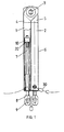
- Figure 1 shows an end view of a hanger in accordance with the present invention
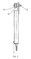
- Figure 2 shows a side view of the hanger of Figure 1
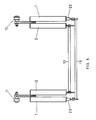
- Figure 3 shows in schematic form the installation of a pair of hangers in a filter press
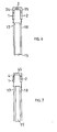
- Figure 4 shows an end view of a first modification of the hanger of Figure 1
- Figure 5 shows this in an installation.
- Figures 6 and 7 show two further modifications of the hanger of Figure 1 in scrap end view.
- the hanger comprises a pair of arms 1, 2, which are hinged at their upper end by a pivot bolt 3, which extends through plate like members 4, 5 respectively welded to the tops of the arms 1, 2.
- Each arm 1, 2 is similar in construction and comprises the hollow tubular outer wall, 6, in which slides a spring loaded rod 7.
- the rod 7 carries at its lower end outside the arm a latching plate 8, which has a keyhole aperture 9, designed to fit over the end of a suspension member for a filter plate.
- the rod 7 carries at its free end within the hollow tubular outer wall 6, a stop member 10, which is screwed to the end of rod 7 and prevents the rod from being completely withdrawn from the tube 6.
- the stop 10 is also profiled to prevent rotation of the rod within the arm 1 and bends on one end of a compression spring 20 which biases the rod in the arm.
- the pivot bolt 3 carries a roller 11, which can run along a support bar 12, extending the length of the side bar filter press on which the hanger is to be used.
- FIG 3 shows a pair of hangers in accordance with the invention in use in a side bar filter press.
- the press in this instance comprises a plurality of filter plates of which only two, 15, 16 are shown. These plates are illustrated in Figure 3 in the open position so that filter cloths 17, 18 associated respectively with each plate can be illustrated. It can be seen that the cloths are supported between the pair of hangers which are at each end of the plate 15 and 16 with the roller 11 of each hanger running along the support 12.
- the latching plate 8 at each arm is fitted onto a support rod 19 comprising the suspension member for each filter cloth and this rod 19 is recessed in a manner (not shown) so that the recess fits into the lower part of the keyhole aperture 9 of each latching plate 8.
- the cloths are suspended by the arms 1, 2 and when the filter plates 15 and 16 are opened the arms 1, 2 pivot about the pivot bolt 3, and open out.
- the cloth washing machine has a sparge arm which is lowered between the cloth and deflectors on the arm push out the supports 19, supporting the cloth thus allowing the sparge arm free downward passage and ensuring that spray nozzles extending from the arm do not catch on the cloth and damage it.
- a high pressure water jet is ejected from each spray and the arm passes down and up the cloth as many times as necessary to dislodge all the solid particles of cake remaining in the cloth and to clean it thoroughly.
- a chain 30 is provided between adjacent pairs of cloth hangers to restrain and centralise each hanger in the chamber between the two plates which are opened.
- FIG. 4 and 5 a first modification of the hanger of Figure 1 is shown here where the arms 1, 2 each have extension members 24, 25, which may be longer than the parts 4, 5 of Figure 1, hinged on the bolt 3.
- the members 24, 25 are flat plates and being of extended length they allow the arms to pivot freely in use without there being any risk fouling on the support bar 12.
- the arm 1 is shown as being effectively longer than the arm 2 by the use of a sleeve 23 which is fitted around the lower end of rod 7 of arm 1.
- the purpose of this extension can clearly be seen from the schematic of Figure 5 where the support rod 19 joining arms 2 is able to be positioned along the rod 19 joining arms 1. This allows for the arms 1 and 2 of each hanger to lie above each other in minimum horizontal space.
- the arm 1 could, of course, be made longer than the arm 2 to achieve the same effect.
- the use of the sleeve 23 is a convenient way of reducing manufacturing costs and allowing common components for arms 1 and 2 to be used.
- FIGs 6 and 7 Two further modifications of the hanger are shown in Figures 6 and 7. These modifications are for filter presses where the hanger supports cloth on either side of a filter plate rather than two adjacent plates, as shown in Figure 3.
- the rod 3 is positioned centrally above filter plate 15 and cloths 17, 18 hang on each side of the plate.
- the arms 1, 2 each have cranked extension members 34, 35 to hold the cloths parallel with their associated side of the plate 15.
- rod 3 is positioned over the cloth and the arm 1 is as shown in Figure 1.
- the arm 2 has an lengthened extension member 45 which is cranked to hold arm 2 over the other side of plate 15 and to suspend cloth 18 parallel to it.
- the operation is swift and speedy as well as king effective.
- the provision of the novel filter cloth hanger provides a means whereby the cloths may be readily replaced when necessary and also they are themselves able easily to be replaced if damaged. However, they are simple in construction and by virtue of this are basically maintenance free.
Landscapes
- Chemical & Material Sciences (AREA)
- Chemical Kinetics & Catalysis (AREA)
- Filtration Of Liquid (AREA)
Claims (13)
Applications Claiming Priority (2)
| Application Number | Priority Date | Filing Date | Title |
|---|---|---|---|
| GB878720722A GB8720722D0 (en) | 1987-09-03 | 1987-09-03 | Filter press cloth hanger |
| GB8720722 | 1987-09-03 |
Publications (3)
| Publication Number | Publication Date |
|---|---|
| EP0306150A2 EP0306150A2 (de) | 1989-03-08 |
| EP0306150A3 EP0306150A3 (en) | 1989-04-12 |
| EP0306150B1 true EP0306150B1 (de) | 1990-09-26 |
Family
ID=10623203
Family Applications (1)
| Application Number | Title | Priority Date | Filing Date |
|---|---|---|---|
| EP88307209A Expired - Lifetime EP0306150B1 (de) | 1987-09-03 | 1988-08-04 | Tuchaufhänger für Filterpresse |
Country Status (8)
| Country | Link |
|---|---|
| US (1) | US4874512A (de) |
| EP (1) | EP0306150B1 (de) |
| CN (1) | CN1031659A (de) |
| AU (1) | AU602786B2 (de) |
| DE (1) | DE3860699D1 (de) |
| ES (1) | ES2018342B3 (de) |
| GB (2) | GB8720722D0 (de) |
| ZA (1) | ZA886056B (de) |
Families Citing this family (5)
| Publication number | Priority date | Publication date | Assignee | Title |
|---|---|---|---|---|
| US5045186A (en) * | 1988-09-22 | 1991-09-03 | Kurita Machinery Manufacturing Company Limited | Filtration method and filter press for employing the method |
| DK0584756T3 (da) * | 1992-08-27 | 1996-02-26 | Truem Clar Tech Fritz Truemmel | Anordning til løsningen af en kammerfilterpresses kager og fremgangsmåde til dens drift |
| US5395523A (en) * | 1994-07-15 | 1995-03-07 | Noritake Iron Works Co., Ltd. | Cake removing apparatus for use in filter press |
| US20180070755A1 (en) * | 2016-09-14 | 2018-03-15 | Shanghai Aiwei Electronic Technology Co., Ltd. | Juicer |
| CN109908661B (zh) * | 2019-03-26 | 2021-05-18 | 安徽省太和县众友筛网滤布制造有限公司 | 一种化工专用工业滤布生产工艺 |
Family Cites Families (8)
| Publication number | Priority date | Publication date | Assignee | Title |
|---|---|---|---|---|
| FR1143088A (fr) * | 1954-10-21 | 1957-09-26 | Usines Meura | Support pour les toiles filtrantes des filtres-presses |
| FR1318283A (fr) * | 1961-03-25 | 1963-02-15 | Hoesch & Soehne Eberhard | Dispositif de détachement du gâteau dans les filtres-presses à plateaux |
| US4129137A (en) * | 1977-11-04 | 1978-12-12 | Kurita Machinery Manufacturing Company Limited | Washing apparatus for filter press |
| JPS60161708A (ja) * | 1984-01-31 | 1985-08-23 | Ngk Insulators Ltd | 懸垂式フイルタ−プレス |
| JPS6140106U (ja) * | 1984-08-17 | 1986-03-13 | 株式会社 栗田機械製作所 | フイルタプレスの洗浄装置 |
| JPH0137686Y2 (de) * | 1984-09-07 | 1989-11-14 | ||
| WO1987001300A1 (fr) * | 1985-09-06 | 1987-03-12 | Kurita Machinery Manufacturing Company Limited | Filtre-presse |
| US4710293A (en) * | 1985-12-09 | 1987-12-01 | Envirotech Corporation | Filter cloth cake removal device |
-
1987
- 1987-09-03 GB GB878720722A patent/GB8720722D0/en active Pending
-
1988
- 1988-08-04 DE DE8888307209T patent/DE3860699D1/de not_active Expired - Lifetime
- 1988-08-04 EP EP88307209A patent/EP0306150B1/de not_active Expired - Lifetime
- 1988-08-04 ES ES88307209T patent/ES2018342B3/es not_active Expired - Lifetime
- 1988-08-09 AU AU20603/88A patent/AU602786B2/en not_active Ceased
- 1988-08-10 US US07/230,423 patent/US4874512A/en not_active Expired - Fee Related
- 1988-08-11 GB GB8819058A patent/GB2209287B/en not_active Expired - Lifetime
- 1988-08-16 ZA ZA886056A patent/ZA886056B/xx unknown
- 1988-09-02 CN CN88106479A patent/CN1031659A/zh active Pending
Also Published As
| Publication number | Publication date |
|---|---|
| EP0306150A3 (en) | 1989-04-12 |
| US4874512A (en) | 1989-10-17 |
| EP0306150A2 (de) | 1989-03-08 |
| ES2018342B3 (es) | 1991-04-01 |
| DE3860699D1 (de) | 1990-10-31 |
| GB8720722D0 (en) | 1987-10-07 |
| GB2209287A (en) | 1989-05-10 |
| CN1031659A (zh) | 1989-03-15 |
| GB8819058D0 (en) | 1988-09-14 |
| ZA886056B (en) | 1989-04-26 |
| AU2060388A (en) | 1989-03-09 |
| AU602786B2 (en) | 1990-10-25 |
| GB2209287B (en) | 1991-02-13 |
Similar Documents
| Publication | Publication Date | Title |
|---|---|---|
| US5855778A (en) | Filter press | |
| US4900454A (en) | Method and means for pressure filtering | |
| EP0306150B1 (de) | Tuchaufhänger für Filterpresse | |
| CN101293152A (zh) | 一种卧式压滤机 | |
| JP2003534893A (ja) | 気体をろ過するフィルタ装置 | |
| CA2195618A1 (en) | Apparatus for Regenerating Filter Clothes of Filter Press | |
| EP0404506B1 (de) | Fluidum-Feststoff-Kontaktvorrichtung mit einem Filter am Fluidumauslass versehen | |
| FI78843C (fi) | Foerfarande foer rengoering av filtertyget i ett kammarfilter samt kammarfilter enligt foerfarandet. | |
| US4584100A (en) | Filter press comprising means for filtering mud | |
| CN118695894A (zh) | 改进的压滤机 | |
| KR20010055350A (ko) | 필터프레스의 여과판 분리장치 | |
| JPH1099607A (ja) | フィルタプレスのろ過装置ユニット | |
| GB2086751A (en) | Platen press | |
| CN210304777U (zh) | 清洗液循环装置及针板清洗机 | |
| KR100630947B1 (ko) | 전처리 설비 | |
| WO2000000679A3 (en) | An apparatus and method for reducing fiber waste by lint cleaners | |
| KR101894884B1 (ko) | 여과판과 분리된 현수축을 갖는 여과포 이동식 필터 프레스 | |
| JP2004073951A (ja) | フィルタープレス | |
| CN216497724U (zh) | 一种污水过滤用水质过滤器 | |
| RU2312699C1 (ru) | Фильтр-пресс с промывным устройством | |
| CN210333538U (zh) | 一种针板清洗装置 | |
| JP3091692B2 (ja) | 濾布固定式フィルタープレス | |
| SU1368006A1 (ru) | Цепной фильтр | |
| US797910A (en) | Print washing and drying machine. | |
| DE2806361A1 (de) | Einschubwagen fuer labor-geschirrspuelmaschinen |
Legal Events
| Date | Code | Title | Description |
|---|---|---|---|
| PUAI | Public reference made under article 153(3) epc to a published international application that has entered the european phase |
Free format text: ORIGINAL CODE: 0009012 |
|
| PUAL | Search report despatched |
Free format text: ORIGINAL CODE: 0009013 |
|
| AK | Designated contracting states |
Kind code of ref document: A2 Designated state(s): BE DE ES IT NL |
|
| 17P | Request for examination filed |
Effective date: 19890207 |
|
| AK | Designated contracting states |
Kind code of ref document: A3 Designated state(s): BE DE ES IT NL |
|
| 17Q | First examination report despatched |
Effective date: 19890707 |
|
| GRAA | (expected) grant |
Free format text: ORIGINAL CODE: 0009210 |
|
| AK | Designated contracting states |
Kind code of ref document: B1 Designated state(s): BE DE ES IT NL |
|
| ITF | It: translation for a ep patent filed | ||
| REF | Corresponds to: |
Ref document number: 3860699 Country of ref document: DE Date of ref document: 19901031 |
|
| PLBE | No opposition filed within time limit |
Free format text: ORIGINAL CODE: 0009261 |
|
| STAA | Information on the status of an ep patent application or granted ep patent |
Free format text: STATUS: NO OPPOSITION FILED WITHIN TIME LIMIT |
|
| PG25 | Lapsed in a contracting state [announced via postgrant information from national office to epo] |
Ref country code: ES Free format text: LAPSE BECAUSE OF EXPIRATION OF PROTECTION Effective date: 19910805 |
|
| PG25 | Lapsed in a contracting state [announced via postgrant information from national office to epo] |
Ref country code: BE Effective date: 19910831 |
|
| 26N | No opposition filed | ||
| BERE | Be: lapsed |
Owner name: COAL INDUSTRY (PATENTS) LTD Effective date: 19910831 |
|
| PG25 | Lapsed in a contracting state [announced via postgrant information from national office to epo] |
Ref country code: NL Effective date: 19920301 |
|
| NLV4 | Nl: lapsed or anulled due to non-payment of the annual fee | ||
| PGFP | Annual fee paid to national office [announced via postgrant information from national office to epo] |
Ref country code: DE Payment date: 19940924 Year of fee payment: 7 |
|
| PG25 | Lapsed in a contracting state [announced via postgrant information from national office to epo] |
Ref country code: DE Effective date: 19960501 |
|
| REG | Reference to a national code |
Ref country code: ES Ref legal event code: FD2A Effective date: 19990601 |
|
| PG25 | Lapsed in a contracting state [announced via postgrant information from national office to epo] |
Ref country code: IT Free format text: LAPSE BECAUSE OF NON-PAYMENT OF DUE FEES;WARNING: LAPSES OF ITALIAN PATENTS WITH EFFECTIVE DATE BEFORE 2007 MAY HAVE OCCURRED AT ANY TIME BEFORE 2007. THE CORRECT EFFECTIVE DATE MAY BE DIFFERENT FROM THE ONE RECORDED. Effective date: 20050804 |