EP0306036B1 - Schweissverfahren mit einem Energiestrahl hoher Leistungsdichte in Verbindung mit einem Widerstandsstumpf-Schweissverfahren und Vorrichtung hierzu - Google Patents
Schweissverfahren mit einem Energiestrahl hoher Leistungsdichte in Verbindung mit einem Widerstandsstumpf-Schweissverfahren und Vorrichtung hierzu Download PDFInfo
- Publication number
- EP0306036B1 EP0306036B1 EP88114343A EP88114343A EP0306036B1 EP 0306036 B1 EP0306036 B1 EP 0306036B1 EP 88114343 A EP88114343 A EP 88114343A EP 88114343 A EP88114343 A EP 88114343A EP 0306036 B1 EP0306036 B1 EP 0306036B1
- Authority
- EP
- European Patent Office
- Prior art keywords
- welding
- upset
- power
- density beam
- driving
- Prior art date
- Legal status (The legal status is an assumption and is not a legal conclusion. Google has not performed a legal analysis and makes no representation as to the accuracy of the status listed.)
- Expired - Lifetime
Links
Images


Classifications
-
- B—PERFORMING OPERATIONS; TRANSPORTING
- B23—MACHINE TOOLS; METAL-WORKING NOT OTHERWISE PROVIDED FOR
- B23K—SOLDERING OR UNSOLDERING; WELDING; CLADDING OR PLATING BY SOLDERING OR WELDING; CUTTING BY APPLYING HEAT LOCALLY, e.g. FLAME CUTTING; WORKING BY LASER BEAM
- B23K31/00—Processes relevant to this subclass, specially adapted for particular articles or purposes, but not covered by any single one of main groups B23K1/00 - B23K28/00
- B23K31/02—Processes relevant to this subclass, specially adapted for particular articles or purposes, but not covered by any single one of main groups B23K1/00 - B23K28/00 relating to soldering or welding
-
- B—PERFORMING OPERATIONS; TRANSPORTING
- B23—MACHINE TOOLS; METAL-WORKING NOT OTHERWISE PROVIDED FOR
- B23K—SOLDERING OR UNSOLDERING; WELDING; CLADDING OR PLATING BY SOLDERING OR WELDING; CUTTING BY APPLYING HEAT LOCALLY, e.g. FLAME CUTTING; WORKING BY LASER BEAM
- B23K11/00—Resistance welding; Severing by resistance heating
- B23K11/04—Flash butt welding
- B23K11/046—Apparatus therefor
-
- B—PERFORMING OPERATIONS; TRANSPORTING
- B23—MACHINE TOOLS; METAL-WORKING NOT OTHERWISE PROVIDED FOR
- B23K—SOLDERING OR UNSOLDERING; WELDING; CLADDING OR PLATING BY SOLDERING OR WELDING; CUTTING BY APPLYING HEAT LOCALLY, e.g. FLAME CUTTING; WORKING BY LASER BEAM
- B23K15/00—Electron-beam welding or cutting
- B23K15/0046—Welding
- B23K15/0053—Seam welding
- B23K15/006—Seam welding of rectilinear seams
-
- B—PERFORMING OPERATIONS; TRANSPORTING
- B23—MACHINE TOOLS; METAL-WORKING NOT OTHERWISE PROVIDED FOR
- B23K—SOLDERING OR UNSOLDERING; WELDING; CLADDING OR PLATING BY SOLDERING OR WELDING; CUTTING BY APPLYING HEAT LOCALLY, e.g. FLAME CUTTING; WORKING BY LASER BEAM
- B23K26/00—Working by laser beam, e.g. welding, cutting or boring
- B23K26/20—Bonding
- B23K26/21—Bonding by welding
- B23K26/24—Seam welding
- B23K26/26—Seam welding of rectilinear seams
- B23K26/262—Seam welding of rectilinear seams of longitudinal seams of tubes
Definitions
- the present invention relates to a high-power-density beam welding in combination with upset welding for metal plates, sheets and wires, or their formed or machined articles, and an apparatus therefor.
- the upset resistance welding methods such as upset welding and flash welding, or high-power-density beam welding methods using laser, electron beam, etc. have been often used to join metal plates, sheets and wires or their formed or machined articles, especially those of relatively small thickness or diameter.
- the upset welding method comprises clamping two parts to be welded to each other on a fixed electrode and a movable electrode respectively, advancing the movable electrode toward the fixed electrode to upset the abutting edges of the parts against each other, and supplying an electric current to the parts while giving a predetermined upsetting pressure onto the abutting edges thereof, to heat the parts with the heat produced therein by the resistances of the parts and the contact resistances of the abutting faces thereof, so as to produce plastic deformations in the parts and weld the parts to each other.
- the flash welding method is performed in the same welding steps and with the same arrangement of the above-described upset welding method, except that flashes are produced between the parts during the welding process to assure heating with higher efficiency.
- these methods present the advantage that the entire area of abutting surface of the parts are joined to each other simultaneously, so that distortions due to the temperature gradient of the weld are smaller than those caused in the arc or beam welding where the edges of the parts are welded to each other along the weld line sequentially by starting from one extremity thereof to the other.
- the former is feasible even if the edge machining is rougher, while the latter is more suited for automation of a welding line which requires a clean working environment, because it produces no flash during the welding process.
- the high-power-density beam welding method comprises parts irradiating a laser beam or high-power-density electron beam onto abutting edges of parts to be joined to fuse and weld the abutting edges.
- This welding method has been widely practised, because it presents great technical and economical merits that the use of a concentrated heat source with high energy density results in narrower heated and fused areas of the parts members and narrower areas of the parts in which the material properties are changed and geometrical deformation is caused.
- the high-power-density beam welding method present the following disadvantages:
- JP-A-57-202985 discloses an electric welding method wherein an electrical contact is effected by laser irradiation first and then the Joule heating is caused by electric conduction. This method is intended to weld two materials remarkably different in their heat capacity.
- EP-A-0,248,143 discloses a method and an apparatus for connecting metal strips by means of flash welding or laser welding. It does, however, not disclose a combined operation of these two welding methods.
- An object of the present invention is not merely to combine the two above-described welding methods for the purpose of offsetting the disadvantages of the two methods with each other, or compensate the disadvantages of the one method with the advantages of the other, but to provide a truly new welding method.
- Fig. 1 is a perspective view showing an embodiment of system configuration according to the present invention.
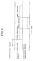
- Fig. 2 is a time chart showing the electric conduction timing to mitigate the quick heating or cooling of welding objects.
- Fig. 3 shows an apparatus according to the present invention.
- Fig. 1 shows the basical configuration of an upset welding system as an embodiment of the present invention.
- 1 is a cut plate.
- 3 is a hydraulic cylinder to give an upsetting force onto the cut plates 1 for butting against each other.
- 4 is a hydraulic cylinder used to clamp the cut plate 1.
- 5 is a nozzle to irradiate a carbon dioxide laser beam. This nozzle may also jet an argon or helium gas for processing.
- 6 is a guide to be used for moving the laser beam along the upset interface, that is, a laser beam transfer tube.
- 2 is a power transformer to supply an electric current to the plates 1. This transformer is operated during the pressure as well as before, during and after the irradiation of the laser beam.
- the cut plates 1 are conductive during the upset welding, they are heated and softened by the resistance heat produced in the upset parts of the plates 1.
- the pressure gives plastic deformations in the abutting surfaces of the plates 1 by pressing the heated abutting surfaces thereof against each other so as to provide a good fitting of the abutting surfaces and form a small excess metal.
- the gapless upset ends of the plates 1 are obtained, and the small excess metal serves as the substitute of welding materials when a high-power-density beam is irradiated. Therefore, the thickness of the plates 1 to be fused by the irradiation of the high-power-density beam is the original thickness of each plate 1 plus the height of the excess metal formed by the preliminary upset welding.
- the height of the excess metal depends upon the upset welding current and pressure. Therefore, the output of the high-power density beam must depend upon the pressure and the heat input provided by the Joule heating during the preliminary upset welding. And the irradiation of the high-power-density beam fuses the incomplete abutting surfaces provided by the preliminary upset welding, and welds the surfaces of the plates 1 to each other completely.
- Fig. 2 shows an example of the electric current supply timing.
- the high-power-density beam is a laser beam
- argon gas a wide area of fusion is provided by the irradiation of the laser beam.
- helium gas the area of fusion is narrower than in case of argon gas.
- argon or helium gas is used as process gas, or whether the mixture of these gas or any other gas is used has to be determined, considering the metallurgical characteristics of the welding objects, the form of the excess metal and the thickness of the plates 1.
- This embodiment according to the present invention is a welding system comprising an upset welding machine and a carbon dioxide laser processing machine.
- an upset welding machine and a laser processing machine separately so as to set and subject the preliminarily upset-welded materials to the fusion welding in the laser processing machine. After the preliminary upset welding, it is also possible to subject the materials to the fusion welding with electron beam.
- JIS G3131 SPHC materials (30mm wide and 3.1mm thick) were subjected to an AC upset welding and a laser welding.
- an upset welding machine and carbon dioxide laser processing machine were used.
- the preliminary upset welding was performed under the conditions as shown in Table 1, while the laser irradiation conditions are as shown in Table 2.
- Table 1 shows that the mechanical force and electric power required for the preliminary upset welding are sufficiently smaller than for the ordinary upset welding, where the welding current of 170 Amp/mm2 and the upsetting force of about 98.1 MPa (10kg/mm2) are required to provide an excellent performance of weld.
- Table 3 shows the weld performance provided by the present invention in comparison with those by the conventional welding methods.
- Table 4 shows the welding efficiencies of these welding methods. These tables show that the welding method according to the present invention is superior to the conventional methods in many aspects.
- Table 1 Preliminary-upset welding conditions AC peak average current Pressure Resistance welding time Upset length 140 Amp/mm2 49 MPa (5kg/mm2) 20 1mm Note: The resistance welding time is represented in AC cycles (50Hz).
- Table 2 Laser beam irradiation conditions Laser output Welding speed Flow rate of process gas 4.0 kwatt 3.0m/min He 15 liters/min Table 4 Method Yield Pre- & post-process time Upset welding (1) bad long Laser welding (2) good long Welding according to this invention (3) good short
- Fig. 3 shows the appearance of a mechanism part in an embodiment of the system according to the present invention.
- the mechanism for driving a laser torch 23 along a weld line is shown to be disassembled with a laser torch support 13 removed from a machine frame 9 and lifted.
- a fixed support 32 and a support 35 are erectly fixed on a base 31 for the upset welding unit. Between the supports 32 and 35, guide beams 331 and 332 are horizontally placed and fixed on the supports 32 and 35.
- An electrode support block 34 is mounted on the guide beams 331 and 332 in such a way that it is freely movable in the x direction.
- first electrode material 1011 extending in the y direction is fixed on the fixed support 32.
- An electrode support block (not shown) is mounted on the fixed support 32 in such a way that it can be moved vertically (or in the z direction).
- a second electrode material 1012 extending in the y direction is fixed on this electrode support block.
- a hydraulic cylinder 36 is inserted between this electrode support block and the fixed support 32.
- the upper chamber and lower chamber of the hydraulic cylinder 36 which are partitioned by a piston rod, are connected to a high-pressure line and a low-pressure line respectively so that when a piston is moved down to project the piston rod out of the cylinder, the second electrode material 1012 can be moved up and strike against the first electrode material 1011. If a wheel material 100 as upset welding object is then placed between the electrodes, it is pressed by and between the electrode materials 1011 and 1012.
- a third electrode material 1021 extending in the y direction is fixed on the electrode support block 34 through an insulating material.
- another electrode support block 52 is mounted in such a way that it can be moved vertically (or in the z direction).
- a fourth electrode material 1022 is fixed on the electrode support block 52 through an insulating material.
- a hydraulic cylinder 7 is inserted between the electrode support block 52 and the electrode support block 34. The cylinder 7 is fixed on the block 52, while a piston rod is on the block 34.
- the upper and lower chambers of the hydraulic cylinder 7, which are partitioned by the piston rod, are connected to a high-pressure line and a low-pressure line respectively so that when a piston is moved down to project the piston rod out of the cylinder, the fourth electrode material 1022 can be moved up and strike against the third electrode material 1021. If a wheel material 100 as upset welding object is then placed between the electrodes, it is pressed by and between the electrode materials 1021 and 1022.
- a hydraulic cylinder 8 is inserted between the electrode support block 34 and the support 35.
- the cylinder 8 is fixed on the block 34, while a piston rod is on the support 35.
- the left and right chambers of the hydraulic cylinder 8, which are partitioned by the piston rod, are connected to a high-pressure line and a low-pressure line respectively so that when a piston is moved right to project the piston rod out of the cylinder 8, the electrode support block 34 can be moved left to move the third and fourth electrode materials 1021 and 1022 to the left.
- the end part of the wheel material 100 is pressed by and between the first and second electrode materials 1011 and 1012, while the other end part of the wheel material 100 is pressed by and between the third and fourth electrode materials 1021 and 1022, as described above, the end part of the wheel material 100 is butted against the other end part thereof with an upsetting force exerted on the end faces (abutting surfaces) of the two end parts. Pressed by the upsetting force, the abutting surfaces are resistance-welded to each other by applying an upset weld voltage to the first and third electrode materials 1011 and 1021. At the same time, the end faces are softened to form angular protrusions on the two end parts around the abutting surfaces.
- the cross section including the weld line is in the form of M.
- a machine frame 9 in the form of ] and extending in the y direction, by which a threaded rod 11 extending in the y direction is free rotatably supported and on which a guide bar 121 is fixed in parallel with the threaded rod.
- another guide bar 122 is fixedly attached in parallel with the threaded rod 11.
- the end of the threaded rod 11 is connected to the output shaft of reduction gears 53 through the machine frame 9.
- the input shaft of the reduction gears 53 is connected to the rotary shaft of an electric motor My and a rotary encoder RE1. This rotary encoder RE1 generates an electric pulse per the predetermined angular rotation of the input shaft of the reduction gears 53.
- the threaded rod 11 is passed through and engaged with the threaded hole of a nut (female screw) fixedly on mounted on the laser torch support 13.
- a nut female screw
- guide seats 151 and 152 having a concave section are connected to and supported by the guide bars 121 and 122. Therefore, when the motor My is normally rotated, the threaded rod 11 is normally rotated to move the laser torch support 13 forward (in the direction from the front side to the back side of the sheet on which Fig. 3 is shown).
- the threaded rod 11 is also reversed to move the laser torch support 13 backward (in the direction from the back side to the front side of the sheet on which Fig. 3 is shown).
- the laser torch support 13 is equipped with a limit switch S1.
- the action element of the limit switch S1 strikes against the machine frame 9 to set the limit switch S1 into open state and consequently stop the energized motor My for reverse rotation (or backward movement).
- a threaded rod 17 and guide bars 181 and 182 designed similarly to the threaded rod 11 and the guide bars 121 and 122 respectively are placed in the x direction.
- the threaded rod 17 is screwed in a nut (not shown) fixed on another laser torch support 19.
- a nut (not shown) fixed on another laser torch support 19.
- guide seats 211 and 212 (212 not shown) having a concave section are connected to and supported by the guide bars 181 and 182.
- the output shaft of reduction gears 54 is connected to the end of the threaded rod 17, while the input shaft of the reduction gears 54 is connected to a motor Mx and a rotary encoder RE2. Therefore, when the motor Mx is normally rotated, the threaded rod 17 is also normally rotated to move the laser torch support 19 forward (or left) relative to the laser torch support 13.
- the threaded rod 17 is also reversed to move the laser torch support 19 backward (or right) relative to the laser torch support 13.
- the laser torch support 19 is also equipped with a limit switch S2.
- the action element of the limit switch S2 strikes against the laser torch support 13 on which the threaded rods 11 and 17 are mounted.
- the limit switch S2 is set into open state to stop the energized motor Mx for reverse rotation (backward movement).
- a mirror box 228 coupled with a laser torch 23.
- a beam duct 226 is inserted in a beam duct 227 fixed on the mirror box 228, the beam duct 226 is fixed on a mirror box 224, which is fixed on the laser torch support 13 through a support 225.
- Another beam duct 223 is fixed on the mirror box 224.
- a beam duct 222 for a laser emitting device 221 is inserted in the beam duct 223.
- the beam duct 227 can be moved forward and backward in the x direction relative to the beam duct 226.
- the beam duct 223 can be moved forward and backward in the y direction relative to the beam duct 222.
- the laser emitting device 221 is fixed on an on-floor support (not shown) separately from the above-described movable parts.
- the laser torch support 13 On the laser torch support 13 are mounted a TV camera 24 and a lighting lamp 25. Therefore, in this embodiment, the laser torch support 13 is moved only in the y direction relative to the machine frame 9 so that the TV camera 24 and the lighting lamp 25 are also moved only in the y direction, while the laser torch support 19 is moved both in the y and x directions relative to the machine frame 9 so that the laser torch 23 is also moved both in the y and x directions.
- the TV camera 24 and the lighting lamp 25 are placed just above the position deviated a little from the right sides of the electrode materials 1011 and 1012 to the right in the x direction, that is, the position where the weld line is formed in the expected upset welding process, and they are moved by the motor My from the x position in the y direction.
- the laser torch 23 is also moved in the y direction, and it is moved further in the x direction when the motor Mx is driven.
- the laser torch 23 is driven in the x direction according to the x-direction deviation of the weld line so that it can always focus its irradiated laser beam on the center of the weld line width during its movement in the y direction.
- the apparatus according to the present invention can be used not only for the upset welding of wheel materials, but also for that of the end faces of plate, belt, band and other materials.
Landscapes
- Engineering & Computer Science (AREA)
- Mechanical Engineering (AREA)
- Physics & Mathematics (AREA)
- Optics & Photonics (AREA)
- Plasma & Fusion (AREA)
- Laser Beam Processing (AREA)
Claims (7)
- Strahlschweißverfahren mit einem Energiestrahl hoher Leistungsdichte in Verbindung mit Widerstandsstumpfschweißen, das umfaßt: die Ausbildung einer durchgehenden Schweißnaht mittels Widerstands stumpfschweißen entlang Stoßkanten von vorzuverschweißenden Metallmaterialien (1) zur Schweißung mit einem Energiestrahl hoher Leistungsdichte und Schweißen der Metallmaterialien (1) durch einen Energiestrahl hoher Leistungsdichte entlang der Schweißnaht, die zuvor durch das Vorstumpfschweißen gebildet wurde, wobei die Leistung des Energiestrahls hoher Leistungsdichte sowohl auf der Basis eines durch Joule'sche Erwärmung erzeugten Wärmeeintrags in die Metallmaterialien (1) während des Stumpfschweißens als auch auf der Basis eines auf die Metallmaterialien (1) ausgeübten Schweißdrucks bestimmt wird.
- Strahlschweißverfahren mit einem Energiestrahl hoher Leistungsdichte in Verbindung mit Widerstandsstumpfschweißen nach Anspruch 1, wobei die Metallmaterialien durch Einspeisen eines elektrischen Stroms in sie vor, während und/oder nach der Bestrahlung mit dem Energiestrahl hoher Leistungsdichte aufgeheizt werden.
- Strahlschweißverfahren mit einem Energiestrahl hoher Leistungsdichte in Verbindung mit Widerstandsstumpfschweißen nach Anspruch 1 oder 2, wobei der Energiestrahl hoher Leistungsdichte ein Laserstrahl mit einer Wellenlänge innerhalb des Bereichs der fernen Infrarotstrahlen ist.
- Strahlschweißverfahren mit einem Energiestrahl hoher Leistungsdichte in Verbindung mit Widerstandsstumpfschweißen nach Anspruch 3, wobei Argon oder ein anderes Gas vor der Bestrahlung mit dem Laserstrahl auf die metallischen Materialien geblasen wird, um das Schmelzen der metallischen Materialien zu erleichtern.
- Strahlschweißverfahren mit einem Energiestrahl hoher Leistungsdichte in Verbindung mit Widerstandsstumpfschweißen nach Anspruch 1 oder 2, wobei der Energiestrahl hoher Leistungsdichte ein Elektronenstrahl ist.
- Stumpfschweißvorrichtung mit:a) einem ersten Teil (10₁₂), das sich in einer y-Richtung erstreckt, um ein Schweißobjekt (100) zu unterstützen;b) einem zweiten Teil (10₁₁), das sich in der y-Richtung erstreckt und dem ersten Teil (10₁₂) in einer z-Richtung, die im wesentlichen senkrecht zu der y-Richtung ist, gegenüberliegt;c) einer ersten Antriebsvorrichtung, um mindestens eines der ersten und zweiten Teile (10₁₂ und 10₁₁) gegen das andere zu bewegen;d) einem dritten Teil (10₂₂), das sich in der y-Richtung erstreckt und dem ersten Teil in einer x-Richtung, die im wesentlichen senkrecht zu der y- und z-Richtung ist, gegenüberliegt;e) einem vierten Teil (10₂₁), das sich in der y-Richtung erstreckt und dem dritten Teil in der z-Richtung gegenüberliegt;f) einer zweiten Antriebsvorrichtung (7), um mindestens eines der dritten und vierten Teile (10₂₂ und 10₂₁) gegen das andere zu bewegen;g) in x-Richtung beweglichen und unterstützenden Vorrichtungen (8, 34, 52) zum Unterstützen und freien Bewegen der dritten und vierten Teile (10₂₂ und 10₂₁) und der zweiten Antriebsvorrichtung (7);h) dritten Antriebsvorrichtungen zum Antreiben der in x-Richtung beweglichen und unterstützenden Vorrichtung in der x-Richtung;i) einer Energieversorgungseinrichtung zur Beaufschlagung des Schweißobjekts (100) mit Energie, das zwischen dem ersten und/oder dem zweiten Teil und zwischen dem dritten und/oder dem vierten Teil angeordnet ist;j) einer Strahl-Bestrahlungsvorrichtung mit einer Brennervorrichtung (23), die zu dem Raum zwischen dem ersten und dem dritten Teil (10₁₂ bzw. 10₂₂) hin ausgerichtet ist; undk) einer in y-Richtung hin- und herbewegenden Antriebsvorrichtung (My) zum Hin- und Herbewegen und Antreiben des Brenners (23) in der y-Richtung;
gekennzeichnet durchl) eine x-Antriebsvorrichtung (Mx) zum Antrieb des Brenners (23) in der x-Richtung;m) Positionsdetektionsvorrichtungen (24, 25) zur Detektion der x-Richtungsposition der Stumpfschweißnaht zwischen dem ersten und dem dritten Teil; undn) eine Schweißsteuerungsvorrichtung zur abwechselnden Erregung der ersten und zweiten Antriebsvorrichtung, der dritten Antriebsvorrichtung und der Energieversorgungseinrichtung, zur Erregung der Antriebsvorrichtung für die y-Hin- und Herbewegung, zur Erregung der x-Richtungs-Antriebsvorrichtung, entsprechend der von der Positionsdetektions-Vorrichtung detektierten Position, um den Brenner entlang der Stumpfschweißnaht zu bewegen, und zur Erregung der Strahl-Bestrahlungsvorrichtung in dieser Reihenfolge. - Stumpfschweißvorrichtung nach Anspruch 6, dadurch gekennzeichnet, daß die Strahl-Bestrahlungsvorrichtung einen Laser aufweist.
Applications Claiming Priority (4)
| Application Number | Priority Date | Filing Date | Title |
|---|---|---|---|
| JP62221562A JPH0832368B2 (ja) | 1987-09-04 | 1987-09-04 | アプセット溶接を併用した高エネルギービーム溶接方法 |
| JP221562/87 | 1987-09-04 | ||
| JP197697/88 | 1988-08-08 | ||
| JP63197697A JPH0246988A (ja) | 1988-08-08 | 1988-08-08 | 突合せ溶接装置 |
Publications (2)
| Publication Number | Publication Date |
|---|---|
| EP0306036A1 EP0306036A1 (de) | 1989-03-08 |
| EP0306036B1 true EP0306036B1 (de) | 1993-03-24 |
Family
ID=26510510
Family Applications (1)
| Application Number | Title | Priority Date | Filing Date |
|---|---|---|---|
| EP88114343A Expired - Lifetime EP0306036B1 (de) | 1987-09-04 | 1988-09-02 | Schweissverfahren mit einem Energiestrahl hoher Leistungsdichte in Verbindung mit einem Widerstandsstumpf-Schweissverfahren und Vorrichtung hierzu |
Country Status (4)
| Country | Link |
|---|---|
| US (1) | US4899030A (de) |
| EP (1) | EP0306036B1 (de) |
| CA (1) | CA1308784C (de) |
| DE (1) | DE3879589T2 (de) |
Families Citing this family (11)
| Publication number | Priority date | Publication date | Assignee | Title |
|---|---|---|---|---|
| JP2507665B2 (ja) * | 1989-05-09 | 1996-06-12 | 株式会社東芝 | 電子管用金属円筒部材の製造方法 |
| FR2694513B1 (fr) * | 1992-08-04 | 1994-11-04 | Lorraine Laminage | Procédé et dispositif de soudage bord à bord de tôles au moyen d'un faisceau laser. |
| JPH08300172A (ja) * | 1995-04-28 | 1996-11-19 | Nkk Corp | 溶接鋼管の製造方法 |
| US5861602A (en) * | 1995-07-24 | 1999-01-19 | International Business Machines Corporation | Snap together PCMCIA cards with laser tack welded seams |
| US20050194424A1 (en) * | 2004-03-03 | 2005-09-08 | Sproat William H. | Apparatus and method for sonic welding and materials forming |
| US8253062B2 (en) * | 2005-06-10 | 2012-08-28 | Chrysler Group Llc | System and methodology for zero-gap welding |
| US7718917B2 (en) * | 2005-07-08 | 2010-05-18 | Gm Global Technology Operations, Inc. | Hybrid laser and resistance welding system and method |
| US8803029B2 (en) * | 2006-08-03 | 2014-08-12 | Chrysler Group Llc | Dual beam laser welding head |
| US8198565B2 (en) * | 2007-04-11 | 2012-06-12 | Chrysler Group Llc | Laser-welding apparatus and method |
| EP3098022B1 (de) | 2015-05-28 | 2019-02-13 | TRUMPF Schweiz AG | Auswechselbares optikmodul für eine laserbearbeitungsmaschine sowie entsprechende laserbearbeitungsmaschine |
| CN109530953B (zh) * | 2019-01-14 | 2021-04-06 | 烟台蓝鲸增材有限公司 | 一种超大型精密锻件组合零变形焊接工艺 |
Family Cites Families (5)
| Publication number | Priority date | Publication date | Assignee | Title |
|---|---|---|---|---|
| JPS57160582A (en) * | 1981-03-31 | 1982-10-02 | Mitsubishi Heavy Ind Ltd | Welding method by energy beam |
| JPS58100982A (ja) * | 1981-12-09 | 1983-06-15 | Nippon Steel Corp | エネルギビ−ム併用電気抵抗溶接法 |
| US4649256A (en) * | 1985-01-10 | 1987-03-10 | Nippon Steel Corporation | High-frequency electric resistance welding method using irradiation with a laser beam |
| AT389662B (de) * | 1985-02-25 | 1990-01-10 | Lisec Peter Glastech Ind | Vorrichtung zum stumpfschweissen |
| JPS62282783A (ja) * | 1986-05-31 | 1987-12-08 | Mitsubishi Electric Corp | 金属ストリツプの接続方法およびその装置 |
-
1988
- 1988-09-02 EP EP88114343A patent/EP0306036B1/de not_active Expired - Lifetime
- 1988-09-02 DE DE8888114343T patent/DE3879589T2/de not_active Expired - Fee Related
- 1988-09-02 CA CA000577068A patent/CA1308784C/en not_active Expired - Lifetime
- 1988-09-06 US US07/240,612 patent/US4899030A/en not_active Expired - Fee Related
Also Published As
| Publication number | Publication date |
|---|---|
| EP0306036A1 (de) | 1989-03-08 |
| DE3879589D1 (de) | 1993-04-29 |
| CA1308784C (en) | 1992-10-13 |
| DE3879589T2 (de) | 1993-07-01 |
| US4899030A (en) | 1990-02-06 |
Similar Documents
| Publication | Publication Date | Title |
|---|---|---|
| AU596267B2 (en) | Improvements in or relating to method of welding | |
| EP0306036B1 (de) | Schweissverfahren mit einem Energiestrahl hoher Leistungsdichte in Verbindung mit einem Widerstandsstumpf-Schweissverfahren und Vorrichtung hierzu | |
| US5567335A (en) | Process and apparatus for welding sheet metal edges | |
| CN1171697C (zh) | 混合电弧/激光焊接工艺,特别用来焊接管子或汽车构件 | |
| US20070007254A1 (en) | Hybrid laser and resistance welding system and method | |
| CN110732794B (zh) | 一种超声波与电磁脉冲复合焊接装置及复合焊接方法 | |
| JP2005515895A (ja) | 高アスペクト比溶接部のための溶接速度を高める方法及び装置 | |
| CN115722816B (zh) | 一种受控脉冲穿孔等离子弧-非轴对称旋转钨极电弧组合焊接方法 | |
| CN115055819B (zh) | 一种预制热力辅助激光焊接陶瓷材料的方法及装备 | |
| CN119187785A (zh) | 一种等轴晶高温合金结构件铸造缺陷的补焊修复方法 | |
| CN116372327B (zh) | 一种用于厚壁双v坡口的双丝免清根mag焊工艺方法 | |
| CN212122075U (zh) | 厚壁钛合金激光-mig复合焊打底层焊接装置 | |
| CN111496383B (zh) | 厚壁钛合金激光-mig复合焊打底层焊接方法及装置 | |
| US3666910A (en) | Method of solid state bonding an article to a tube surface | |
| CN116441728B (zh) | 一种用于焊接异种材料的三激光束流水线装置及方法 | |
| US5130511A (en) | Method of and apparatus for welding panel with space defined therein | |
| JPH0530555B2 (de) | ||
| CN117245180A (zh) | 一种激光导引复杂空间轨迹埋弧焊接方法 | |
| CN111360408B (zh) | 一种H04MnNi2Ti钢三明治结构激光GMAW复合焊接方法 | |
| CN211516554U (zh) | 一种柜体自动焊接装置 | |
| CN217253832U (zh) | 一种高度自动化的机器人自动焊接装置 | |
| JP3767359B2 (ja) | 突合わせ溶接方法及び溶接結合薄鋼板 | |
| CN218612265U (zh) | 一种钣金件激光焊接设备 | |
| CN113523575A (zh) | 激光-mig、tig多种热源焊接铝合金的焊接方法及装置 | |
| CN219703885U (zh) | 一种镍丝-钼杆上下对焊用引出线热熔焊接装置 |
Legal Events
| Date | Code | Title | Description |
|---|---|---|---|
| PUAI | Public reference made under article 153(3) epc to a published international application that has entered the european phase |
Free format text: ORIGINAL CODE: 0009012 |
|
| AK | Designated contracting states |
Kind code of ref document: A1 Designated state(s): DE FR GB IT |
|
| 17P | Request for examination filed |
Effective date: 19890829 |
|
| 17Q | First examination report despatched |
Effective date: 19901206 |
|
| GRAA | (expected) grant |
Free format text: ORIGINAL CODE: 0009210 |
|
| ITF | It: translation for a ep patent filed | ||
| AK | Designated contracting states |
Kind code of ref document: B1 Designated state(s): DE FR GB IT |
|
| REF | Corresponds to: |
Ref document number: 3879589 Country of ref document: DE Date of ref document: 19930429 |
|
| ET | Fr: translation filed | ||
| PLBE | No opposition filed within time limit |
Free format text: ORIGINAL CODE: 0009261 |
|
| STAA | Information on the status of an ep patent application or granted ep patent |
Free format text: STATUS: NO OPPOSITION FILED WITHIN TIME LIMIT |
|
| 26N | No opposition filed | ||
| PGFP | Annual fee paid to national office [announced via postgrant information from national office to epo] |
Ref country code: GB Payment date: 19970826 Year of fee payment: 10 |
|
| PGFP | Annual fee paid to national office [announced via postgrant information from national office to epo] |
Ref country code: DE Payment date: 19970905 Year of fee payment: 10 |
|
| PGFP | Annual fee paid to national office [announced via postgrant information from national office to epo] |
Ref country code: FR Payment date: 19970909 Year of fee payment: 10 |
|
| PG25 | Lapsed in a contracting state [announced via postgrant information from national office to epo] |
Ref country code: GB Free format text: LAPSE BECAUSE OF NON-PAYMENT OF DUE FEES Effective date: 19980902 |
|
| GBPC | Gb: european patent ceased through non-payment of renewal fee |
Effective date: 19980902 |
|
| PG25 | Lapsed in a contracting state [announced via postgrant information from national office to epo] |
Ref country code: FR Free format text: LAPSE BECAUSE OF NON-PAYMENT OF DUE FEES Effective date: 19990531 |
|
| PG25 | Lapsed in a contracting state [announced via postgrant information from national office to epo] |
Ref country code: DE Free format text: LAPSE BECAUSE OF NON-PAYMENT OF DUE FEES Effective date: 19990701 |
|
| REG | Reference to a national code |
Ref country code: FR Ref legal event code: ST |
|
| PG25 | Lapsed in a contracting state [announced via postgrant information from national office to epo] |
Ref country code: IT Free format text: LAPSE BECAUSE OF NON-PAYMENT OF DUE FEES;WARNING: LAPSES OF ITALIAN PATENTS WITH EFFECTIVE DATE BEFORE 2007 MAY HAVE OCCURRED AT ANY TIME BEFORE 2007. THE CORRECT EFFECTIVE DATE MAY BE DIFFERENT FROM THE ONE RECORDED. Effective date: 20050902 |