EP0305576A1 - Stirrer for an industriel mixing machine - Google Patents
Stirrer for an industriel mixing machine Download PDFInfo
- Publication number
- EP0305576A1 EP0305576A1 EP19870112895 EP87112895A EP0305576A1 EP 0305576 A1 EP0305576 A1 EP 0305576A1 EP 19870112895 EP19870112895 EP 19870112895 EP 87112895 A EP87112895 A EP 87112895A EP 0305576 A1 EP0305576 A1 EP 0305576A1
- Authority
- EP
- European Patent Office
- Prior art keywords
- impeller
- stirring
- impeller part
- parts
- tool according
- Prior art date
- Legal status (The legal status is an assumption and is not a legal conclusion. Google has not performed a legal analysis and makes no representation as to the accuracy of the status listed.)
- Granted
Links
Images


Classifications
-
- B—PERFORMING OPERATIONS; TRANSPORTING
- B01—PHYSICAL OR CHEMICAL PROCESSES OR APPARATUS IN GENERAL
- B01F—MIXING, e.g. DISSOLVING, EMULSIFYING OR DISPERSING
- B01F27/00—Mixers with rotary stirring devices in fixed receptacles; Kneaders
- B01F27/05—Stirrers
- B01F27/11—Stirrers characterised by the configuration of the stirrers
- B01F27/112—Stirrers characterised by the configuration of the stirrers with arms, paddles, vanes or blades
Definitions
- the invention relates to a stirring tool for an industrial mixing or stirring machine, comprising a shaft which can be rotated by a motor and at least two stirring blades attached to it.
- a stirring tool is generally known.
- Stirring tools of this type are used for mixing and stirring in pourable, in particular liquid and pasty media, as well as for emulsifying and dispersing.
- Stirring tools for laminar stirring and mixing systems include frame stirrers, anchor, grid and finger stirrers.
- Stirring tools for turbulent stirring and mixing systems include propeller, turbine, disc, basket (or cyclone), bar and / or cross bar stirrers.
- the type of mixing tool used depends on the objective of the mixing or mixing process. For example, a gentle or intensive mixing, or rapid heat transfer or sedimentation-preventing stirring action and the aforementioned dispersion or the homogenization of solid or liquid aggregates in a carrier fluid may be required.
- the invention has for its object to provide a stirring tool of the type mentioned that can be quickly and easily adapted to a variety of different uses and conditions.
- the invention provides an agitating tool that can be easily adapted to the requirements by adjusting its impeller parts or by exchanging them with other impeller parts. It is thus possible to achieve a wide range of adaptation to the respective task with one and the same stirring blades, so that the necessary storage of stirring tools can be reduced accordingly.
- the invention makes use of the knowledge that the displacement capacity and thus the process-related effect of each stirring element is due to the stirring tool projecting into the stirring product area is determined. When using a planar stirring tool, it is thus possible to change this projected stirring blade surface by changing the angle of attack. This results not only in a change in the power consumption on the stirring tool shaft, but also in a change in the flow effects caused by the rotation of the stirring tool in the material to be stirred.
- This adjustment of the agitator blades can be done in a much shorter time than a complete exchange of agitators. It is thus possible to adapt the shape of the stirring tool to the respective needs to a much finer extent than can be achieved by exchanging stirring tools if a reasonable effort is adhered to.
- impeller parts are designed so that the blade width decreases in the radial direction from the inside to the outside, so that on the one hand such a blade can be optimally dimensioned from the point of view of strength, and on the other hand the different linear speeds of rotation depending on the radius are taken into account.
- the lower orbital velocity in the vicinity of the orbital axis requires a larger effective projected area in order to achieve the same flow effect in the material to be stirred than a larger orbiting radius.
- the stirring tool therefore offers a larger area near the axis of rotation than far from the axis of rotation.
- variable angle adjustment of the impeller parts makes it easy to change the power consumption and displacement efficiency in fluid media.
- each agitator blade also allows the flow conditions in the radially outer area to be set independently of those in the radially inner area, since according to the invention the individual parts of an agitator blade can be rotated independently of one another and can be fixed in the selected positions.
- the impellers are essentially flat structures with essentially flat surfaces, but the invention also provides special impeller parts which are provided, for example, with a Venturi nozzle or with ribs running obliquely parallel to one another.
- Intensive radial flow components and shear forces in the agitated material can be achieved by means of inclined ribs, which are attached to the wings, these ribs running obliquely to a circumferential radius, with the flow radially outwards, radially inwards, angled upwards or downwards depending on the angular position can be performed, again depending on the inclination of the agitator blade part carrying these ribs against the circumferential plane.
- agitator blades are arranged one above the other in several stages, the flow effects in a container equipped with the agitator tool can be influenced in a special way by suitable selection of the settings of the agitator blade parts.
- Flow patterns of various types can be set therein, in particular also countercurrents, which lead to particularly intensive mixing.
- a radially inwardly directed flow component can be imparted to the material to be stirred in one stage, while a radially outwardly directed flow component is generated in the adjacent stage.
- flow components can also be generated parallel to the axis of the shaft of the stirring tool, which run opposite to the axis near the axis near the axis.
- the invention enables the mixing tool to be optimally adapted to a given motor power or rated speed of the drive motor, i.e. adjust the stirrer if necessary, taking into account a possibly not reached optimum of the stirring action, so that just the nominal power or the nominal speed of the drive motor for the stirrer is achieved.
- the invention makes it possible, if necessary, to approach this position of the agitator blade parts of the agitating tool, which can achieve such conditions on the drive shaft, by experiment.
- Fig. 1 shows a partial representation of an agitator tool and can thereby fully recognize the inventive design of an impeller.
- only one impeller 100 is shown attached to a drive shaft 0 in a rotationally fixed manner, while a second impeller, which is rotationally symmetrical to the first impeller 100 and is at the same axial height, is only indicated.
- the impeller 100 consists in the present case of three parts 10, 20 and 30, which in seen in the radial direction are arranged one behind the other.
- the first, radially inner impeller part 10 is connected in a rotationally fixed manner to the drive shaft 0 by means of a bush 40.
- the second, middle impeller part 20 is attached to the radially outer end of the first impeller part 10.
- the third, radially outer impeller part 30 is attached to the radially outer end of the second impeller part 20.
- the three agitator blade parts 10, 20, 30 are designed as flat, blade-like plates which extend essentially in the radial direction. All connections of the impeller parts with the socket 40 or with one another are designed such that the impeller parts are freely rotatable, each with a radius to the drive shaft 0 as the axis of rotation, and can be fixed in their rotational positions. Details of this will be discussed later.
- Fig. 1 it can be seen from an upper edge visible on the impeller part 10 and a lower edge visible on the impeller parts 20 that these impeller parts are inclined in opposite directions to a plane in which the impeller 100 rotates, while the outer impeller part 30 transversely to the direction of the Orbital movement around the axis of the drive shaft 0.
- a radially extending with respect to the circumferential axis of the drive shaft 0 sleeve 11 is welded to the radially inner end of the first impeller part 10, which is inserted into a corresponding recess formed longitudinally in the impeller part 10 and ver at the edges thereof is welded.
- the impeller part 10 is provided with an approximately circular opening 12. The inner end of the sleeve 11 protrudes into this opening 12.
- the first agitator blade part 10 is provided with two bores 13 one behind the other in the radial direction with respect to the axis of the drive shaft 0, which serve to fasten a connecting element 50.
- the bush 40 is mounted on the drive shaft 0 in a rotationally fixed manner by means of a wedge 41.
- Other anti-rotation devices such as slot wedge connections, clamping screws screwed through the bushing 40 and the like, can also be used.
- the bushing 40 carries a plurality of radially extending connecting pins 42 which are evenly distributed in the circumferential direction, one of which is shown in FIG. 2.
- the connecting pin 42 has a collar 43 which is integrally connected to it and by means of which the connecting pin 42 is fastened to the socket 40 by welding.
- the sleeve 11 of the first impeller part 10 is pushed onto the pin 42. Your free, i.e. end pointing away from the impeller part 10 is supported on the collar 43.
- the pin 42 carries at its free end a threaded portion 44 onto which a nut 45 is screwed, with the aid of which the impeller part 10 is thus fastened to the bush 40.
- the nut 45 is accessible for a suitable tool due to the opening 12 in the impeller part 10.
- the width of the impeller part 10 decreases from the inside to the outside. This takes into account the various speeds at which the impeller part 10 strikes the material to be treated.
- FIG. 3 shows the middle impeller part 20 from FIG. 1 in a side view. This is designed essentially in the same way as the first impeller part 10, but its dimensions may be smaller, as shown in FIG. 1.
- the details of the second impeller part 20, which correspond to those of the impeller part 10 of FIG. 1, are provided with reference numerals increased by 10 and need not be explained again.
- FIG. 3 also shows the connecting element 50, with which the first and second impeller parts 10 and 20 are connected to one another.
- the connecting element 50 has a forked shaft 51 and a connecting pin 52. At the transition between the forked shaft 51 and the pin 52, the connecting element 50 carries a collar 53 formed integrally with it. At the free end of the pin 52, a threaded section 54 is formed.
- the sleeve 21 of the second impeller part 20 is pushed onto the pin 52 and secured there in a rotationally fixed manner by means of a nut 55 screwed onto the threaded section 54.
- the second impeller part 20 can be rotated on the pin 52 and fixed by tightening the nut 55 in any selected position.
- the impeller part 20 has two bores 23, which are used to attach a connecting element 60 for connecting the third, outer impeller part 30.
- FIG. 4 shows the third, outer impeller part 30 in a top view (FIG. 4a) and in a lateral section (FIG. 4b).
- FIG. 4b also shows the type of attachment to the middle impeller part 20, which corresponds entirely to the type of attachment of the middle impeller part 20 to the first impeller part 10.
- the third, outer impeller part 30 is relatively short in the radial direction compared to the other impeller parts 10 and 20, but is relatively wide for this. It carries on both sides approximately perpendicular to the surface extension of this impeller part 30, blades 34 extending parallel to one another, which begin at the radially outer edge and extend obliquely over about a third of the radial extent of the impeller part 30. These blades 34 are intended to produce a special shearing action in the material to be treated and to promote emulsification processes.
- the angle that the blades form with the drive shaft radius is 30 to 60 °.
- the third impeller part 30 is fastened to the second impeller part 20 by means of the connecting element 60 already mentioned, which is completely the same as the connecting element 50 and, like that, allows the rotary positions of the third impeller part 30 to be freely selected with respect to the second impeller part 20.
- the details of the connector 60, those of the connector 50 correspond to reference numerals increased by 10, which therefore speak for themselves, so that a repetition of the explanation can be omitted.
- the forked shaft 61 sandwiches the second impeller part 20 between them.
- the shaft 61 is provided with two bores 66 which are aligned with the bores in the second impeller part 20. Screw bolts 67 are screwed through these holes.
- FIG. 5 shows an alternative embodiment of an impeller part 70 which can be used as a radially external part and which is essentially characterized by a Venturi nozzle 74.
- This impeller part consists of a plate 70 'which, in the manner of the impeller parts described above, carries a sleeve 71 for attachment to a connecting element 60 in the manner already explained, which ends in an opening 72.
- the aforementioned Venturi nozzle 74 is welded to this plate 70 at the end facing away from the sleeve 71.
- the Venturi nozzle 74 consists of two trapezoidal side plates 75, one of which is welded to the plate 70 ', and two cover plates 76 connecting the two side plates 75 to one another, which converge and form a funnel-shaped inlet, as in Fig. 5 in the two Sectional views to the right of the side view is shown.
- the direction of flow of the material into the Venturi nozzle 74 when the stirring tool rotates is indicated in the sectional views in FIG. 5 by arrows.
- the impeller part 70 can be rotated on the connecting element 60 and fixed in any rotational position.
- the right sectional view in FIG. 5 shows a position in which the Venturi nozzle 74 is rotated by an angle ⁇ with respect to the sectional view shown to the left thereof.
- this Venturi nozzle When circulating in fluid media, this Venturi nozzle causes it to compress as it passes through the nozzle, depending on the speed of movement of the Venturi nozzle in the medium. Depending on the angular position, the achievable stirring intensities can be set. This affects not only the compression within the nozzle but also the flow around the nozzle.
- the ram jet effect of the Venturi nozzle causes compression of the stirred medium and thus a high flow velocity of the same in the nozzle, in contrast to the areas of the medium to be stirred which are not covered by the Venturi nozzle, as a result of which homogenization processes can be accelerated.
- Fig. 6 shows a side view and a top view of two rotationally symmetrical outer agitator blade parts 80, in which agitator blades 80 'approximately trapezoidal shape with Venturi nozzles 84 are integrally combined.
- the Venturi nozzles 84 are arranged in a rotationally symmetrical manner with respect to the axis, which is only shown schematically here, so that they each have the same effects when circulating through the material to be stirred. It is understood that in this case, too, the impeller parts 80 can be brought into arbitrary angular positions and can be fixed in them. The facilities required for this need not be explained again.
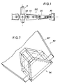
- Fig. 7 shows a perspective view as a detail of the end of an impeller part 80 from Fig. 6. It can be seen that in the region of the free end of the plate 80 'a breakthrough is formed in which a Venturi nozzle 84 is used, the structure of which 5 is completely the same, which is why a more detailed explanation can be dispensed with here.
- the Venturi nozzle 84 is preferably fixed in the cutout in the plate 80 'by welding.
- FIG. 8 shows in a rotationally symmetrical arrangement with respect to the axis of the drive shaft 0 shown only schematically, two outer impeller parts 90, which are designed as flat, to the free end narrowing plates 90 '. These plates 90 'are each provided at the radially outer end with a central incision S, which extends in the example shown over about 25% of the length of each plate 90'.
- the flags 94 and 95 lying on both sides of this incision S are crossed in opposite directions, i.e. bent out of the plane in which the remaining portion of the plate 90 'extends.
- FIG. 8a shows the representation from the side, while FIG. 8b shows an end view from which the different directions of entanglement of the flags 94 and 95 can be clearly seen.
- FIG. 8b also shows that one impeller part 90 has an opposite position to the other impeller part with respect to an orbital plane around the axis of the drive shaft 0.
- the stirring tool is extremely versatile and can be largely adapted to the respective needs.
- the amount of stirring tools or stirring tool parts to be kept can be considerably reduced.
Abstract
Description
Die Erfindung bezieht sich auf ein Rührwerkzeug für eine industrielle Misch- oder Rührmaschine, enthaltend eine von einem Motor in Drehung versetzbare Welle und wenigstens zwei daran befestigte Rührflügel. Ein solches Rührwerkzeug ist allgemein bekannt.The invention relates to a stirring tool for an industrial mixing or stirring machine, comprising a shaft which can be rotated by a motor and at least two stirring blades attached to it. Such a stirring tool is generally known.
Rührwerkzeuge dieser Art werden zum Mischen und Rühren in schüttfähigen, insbesondere flüssigen und pastösen Medien verwendet, sowie zum Emulgieren und Dispergieren.Stirring tools of this type are used for mixing and stirring in pourable, in particular liquid and pasty media, as well as for emulsifying and dispersing.
In der Praxis wird zwischen "laminaren" und "turbulenten" Rühr-und Mischsystemen unterschieden. Rührwerkzeuge für laminare Rühr- und Mischsysteme umfassen Rahmenrührer, Anker-, Gitter- und Fingerrührorgane. Rührwerkzeuge für turbulente Rühr- und Mischsysteme umfassen Propeller- , Turbinen- , Scheiben- , Korb- (oder Zyklon- ), Balken- und/oder Kreuzbalkenrührer. Die jeweils verwendete Rührwerkzeugart hängt von der jeweiligen Zielsetzung des Rühr- oder Mischvorgangs ab. Es kann beispielsweise eine produktschonende oder intensive Durchmischung verlangt werden, oder schnelle Wärmeübergänge oder eine Sedimentation verhindernde Rührwirkung und die schon erwähnte Dispergierung oder die Homogenisierung von festen oder flüssigen Zuschlägen in einem Trägerfluid.In practice, a distinction is made between "laminar" and "turbulent" stirring and mixing systems. Stirring tools for laminar stirring and mixing systems include frame stirrers, anchor, grid and finger stirrers. Stirring tools for turbulent stirring and mixing systems include propeller, turbine, disc, basket (or cyclone), bar and / or cross bar stirrers. The type of mixing tool used depends on the objective of the mixing or mixing process. For example, a gentle or intensive mixing, or rapid heat transfer or sedimentation-preventing stirring action and the aforementioned dispersion or the homogenization of solid or liquid aggregates in a carrier fluid may be required.
Diese unterschiedlichen Zielsetzungen sowie Materialbedingungen erfordern entsprechend dimensionierte Rührwerkzeuge, was in der Praxis ein umfangreiches Lager an Rührwerkzeugen notwendig macht, wenn unterschiedlichen Zielsetzungen und Betriebsbedingungen, auch unter Beachtung vorgegebener Motorleistungen und Drehzahlen für den Antrieb der Rührwerkzeugwelle Rechnung getragen werden soll.These different objectives and material conditions require appropriately dimensioned agitators, which in practice requires an extensive inventory of agitators if different objectives and operating conditions are to be taken into account, also taking into account the specified engine power and speeds for driving the agitator shaft.
Die Auswahl eines geeigneten Rührwerkzeugs wird bei der Herstellung eines neuen Produktes häufig empirisch getroffen. Dies macht mitunter eine Vielzahl von Versuchen mit einem häufigen Austausch der Rührwerkzeuge notwendig und ist daher zeitaufwendig.The selection of a suitable stirring tool is often made empirically when producing a new product. This sometimes makes a large number of attempts with frequent replacement of the stirring tools necessary and is therefore time-consuming.
Der Erfindung liegt die Aufgabe zugrunde, ein Rührwerkzeug der eingangs genannten Art anzugeben, das schnell und einfach einer Vielzahl unterschiedlicher Verwendungszwecke und Einsatzbedingungen angepasst werden kann.The invention has for its object to provide a stirring tool of the type mentioned that can be quickly and easily adapted to a variety of different uses and conditions.
Diese Aufgabe wird durch die kennzeichnenden Merkmale des Anspruchs 1 gelöst. Vorteilhafte Ausgestaltungen der Erfindung sind Gegenstand der Unteransprüche.This object is achieved by the characterizing features of claim 1. Advantageous embodiments of the invention are the subject of the dependent claims.
Die Erfindung schafft ein Rührwerkzeug, das leicht den Erfordernissen angepasst werden kann, indem seine Rührflügelteile verstellt oder aber auch gegen Rührflügelteile anderer Gestalt ausgetauscht werden können. Es ist somit möglich, mit ein und denselben Rührflügeln eine Anpassung an die jeweilige Aufgabe in weiten Umfang zu erzielen, so daß die notwendige Lagerhaltung an Rührwerkzeugen entsprechend verringerbar ist. Die Erfindung macht von der Erkenntnis gebrauch, daß die Verdrängungskapazität und damit die prozessbezogene Wirkung eines jeden Rührorgans durch die sich in das Rührprodukt projizierende Rührwerkzeug fläche bestimmt ist. Bei Verwendung eines flächenhaften Rührwerkzeuges ist es somit möglich, diese projizierte Rührblattfläche durch Veränderung des Anstellwinkels zu verändern. Damit ergibt sich nicht nur eine Änderung in der Leistungsaufnahme an der Rührwerkzeugwelle, sondern auch eine Änderung in den Stömungswirkungen, die vom Umlauf des Rührwerkzeugs im Rührgut hervorgerufen werden. Dieses Verstellen der Rührwerkzeugflügel kann in sehr viel kürzerer Zeit erfolgen, als ein vollständiger Austausch von Rührwerkzeugen. Es ist damit möglich, die Rührwerkzeuggestalt in sehr viel feinerem Umfang an die jeweiligen Bedürfnisse anzupassen, als dies bei Einhaltung eines vernünftigen Aufwandes durch einen Austausch von Rührwerkzeugen erzeilbar ist.The invention provides an agitating tool that can be easily adapted to the requirements by adjusting its impeller parts or by exchanging them with other impeller parts. It is thus possible to achieve a wide range of adaptation to the respective task with one and the same stirring blades, so that the necessary storage of stirring tools can be reduced accordingly. The invention makes use of the knowledge that the displacement capacity and thus the process-related effect of each stirring element is due to the stirring tool projecting into the stirring product area is determined. When using a planar stirring tool, it is thus possible to change this projected stirring blade surface by changing the angle of attack. This results not only in a change in the power consumption on the stirring tool shaft, but also in a change in the flow effects caused by the rotation of the stirring tool in the material to be stirred. This adjustment of the agitator blades can be done in a much shorter time than a complete exchange of agitators. It is thus possible to adapt the shape of the stirring tool to the respective needs to a much finer extent than can be achieved by exchanging stirring tools if a reasonable effort is adhered to.
Vorzugsweise sind Rührflügelteile so gestaltet, daß die Flügelbreite in radialer Richtung von innen nach außen abnimmt, so daß zum einen ein solcher Flügel vom Festigkeitsstandpunkt her optimal dimensionierbar ist, andererseits auch den unterschiedlichen linearen Umlaufgeschwindigkeiten in Abhängigkeit vom Radius Rechnung getragen ist. Die geringere Umlaufgeschwindigkeit in der Nähe der Umlaufachse erfordert eine größere wirksame projizierte Fläche zur Erzielung der gleichen Strömungswirkung im Rührgut als ein größerer Umlaufradius. Das Rührwerkzeug bietet daher nahe der Umlaufachse dem Rührgut eine größere Fläche an, als fern von der Umlaufachse.Preferably, impeller parts are designed so that the blade width decreases in the radial direction from the inside to the outside, so that on the one hand such a blade can be optimally dimensioned from the point of view of strength, and on the other hand the different linear speeds of rotation depending on the radius are taken into account. The lower orbital velocity in the vicinity of the orbital axis requires a larger effective projected area in order to achieve the same flow effect in the material to be stirred than a larger orbiting radius. The stirring tool therefore offers a larger area near the axis of rotation than far from the axis of rotation.
Die variable Winkelanstellung der Rührflügelteile ermöglicht es, die Leistungsaufnahme und die Verdrängungseffizienz in fluiden Medien in einfacher Weise zu verändern. Je flacher der Anstellwinkel ist, desto geringer ist die Leistungsaufnahme des Rührflügels in Abhängigkeit von der Umfangsgeschwindigkeit und der Flächenprojektion.The variable angle adjustment of the impeller parts makes it easy to change the power consumption and displacement efficiency in fluid media. The flatter the angle of attack, the lower the power consumption of the impeller depending on the peripheral speed and the surface projection.
Die mehrteilige Ausführung eines jeden Rührflügels erlaubt es zudem, die Stömungsverhältnisse im radial außenliegenden Bereich unabhängig von denen im radial innenliegenden Bereich einzustellen, da gemäß der Erfindung die einzelnen Teile eines Rührflügels unabhängig von einander gegeneinander verdrehbar sind und in den gewählten Stellungen festgelegt werden können. Gewöhnlich sind die Rührflügel im wesentlichen flächenhafte Gebilde mit im wesentlichen ebenen Oberflächen, doch sieht die Erfindung auch Sonder-Rührflügelteile vor, die beispielsweise mit einer Venturidüse oder mit parallel zueinander schrägverlaufenden Rippen versehen sind. Mit solchen Rührflügelteilen können besondere Strömungseffekte im Rührgut hervorgerufen werden, beispielsweise eine lokale Verdichtung in Abhängigkeit von der Umfangsgeschwindigkeit, wobei auch diese Wirkungen durch Veränderung der Neigungsstellung des betreffenden Rührflügelteils gegenüber der Ebene, in der das Rührflügelteil umläuft, geändert werden kann. Mittels solcher Venturidüsen wird insbesondere die Homogenisierung flüssiger Medien verbessert.The multi-part design of each agitator blade also allows the flow conditions in the radially outer area to be set independently of those in the radially inner area, since according to the invention the individual parts of an agitator blade can be rotated independently of one another and can be fixed in the selected positions. Usually, the impellers are essentially flat structures with essentially flat surfaces, but the invention also provides special impeller parts which are provided, for example, with a Venturi nozzle or with ribs running obliquely parallel to one another. With such agitator blade parts, special flow effects can be caused in the material to be stirred, for example local compression depending on the peripheral speed, and these effects can also be changed by changing the inclination position of the agitator blade part in relation to the plane in which the agitator blade part rotates. The homogenization of liquid media is improved in particular by means of such Venturi nozzles.
Mittels schrägstehender Rippen, die auf den Flügeln angebracht sind, wobei diese Rippen schräg zu einem Umlaufradius verlaufen, lassen sich intensive radiale Strömungskomponenten und Scherkräfte im Rührgut erzielen, wobei je nach Winkelstellung die Strömung radial nach außen, radial nach innen, winkelig nach oben oder unten geführt werden kann, auch dies wieder in Abhängigkeit von der Neigungsstellung des diese Rippen tragenden Rührflügelteils gegen die Umlaufebene.Intensive radial flow components and shear forces in the agitated material can be achieved by means of inclined ribs, which are attached to the wings, these ribs running obliquely to a circumferential radius, with the flow radially outwards, radially inwards, angled upwards or downwards depending on the angular position can be performed, again depending on the inclination of the agitator blade part carrying these ribs against the circumferential plane.
Wenn Rührflügel in mehreren Stufen übereinander angeordnet sind, lassen sich durch geeignete Auswahl der Einstellungen der Rührflügelteile die Strömungswirkungen in einem Behälter, der mit dem Rührwerkzeug ausgerüstet ist, in besonderer Weise beeinflussen.If agitator blades are arranged one above the other in several stages, the flow effects in a container equipped with the agitator tool can be influenced in a special way by suitable selection of the settings of the agitator blade parts.
Es können darin Strömungsbilder vielfältiger Art eingestellt werden, insbesondere auch Gegenströmungen, die zu einer besonders intensiven Durchmischung führen. Es kann beispielsweise dem Rührgut in der einen Stufe eine radial nach innen gerichtete Strömungskomponente vermittelt werden, während in der benachbarten Stufe eine radial nach außen gerichtete Strömungskomponente erzeugt wird. Ebenso können auch Strömungskomponenten parallel zur Achse der Welle des Rührwerkzeugs erzeugt werden, die fern der Achse entgegengesetzt zu denjenigen nahe der Achse verlaufen.Flow patterns of various types can be set therein, in particular also countercurrents, which lead to particularly intensive mixing. For example, a radially inwardly directed flow component can be imparted to the material to be stirred in one stage, while a radially outwardly directed flow component is generated in the adjacent stage. Likewise, flow components can also be generated parallel to the axis of the shaft of the stirring tool, which run opposite to the axis near the axis near the axis.
Im Betrieb ermöglicht die Erfindung, das Rührwerkzeug an eine gegebene Motorleistung oder Nenndrehzahl des Antriebsmotors optimal anzupassen, d.h. das Rührwerkzeug ggf. unter Inkaufnahme eines möglicherweise nicht erreichten Optimums der Rührwirkung so einzustellen, daß gerade die Nennleistung bzw. die Nenndrehzahl des Antriebsmotors für das Rührwerkzeug erzielt wird. Die Erfindung erlaubt es dabei, sich an eine solche Stellung der Rührflügelteile des Rührwerkzeugs, die solche Verhältnisse an der Antriebswelle erzielen läßt, ggf. durch Versuche heranzutasten.In operation, the invention enables the mixing tool to be optimally adapted to a given motor power or rated speed of the drive motor, i.e. adjust the stirrer if necessary, taking into account a possibly not reached optimum of the stirring action, so that just the nominal power or the nominal speed of the drive motor for the stirrer is achieved. The invention makes it possible, if necessary, to approach this position of the agitator blade parts of the agitating tool, which can achieve such conditions on the drive shaft, by experiment.
Bei Verwendung von flächenhaften, blattförmigen Rührflügelteilen läßt sich bei der Bearbeitung von fluiden Medien, die zur Sedimentation neigende Bestandteile enthalten, durch geeignete Einstellung des Anstellwinkels der Rührflügelteile gegen die Umlaufebene erreichen, daß eine solche Sedimentation behindert wird. Dies wird durch solche Einstellungen erreicht, die in Bereichen, wo eine Sedimentation bevorzugt aufzutreten pflegt, beispielsweise unter der Rührwerkzeugwelle oder im Zentrum eines Rührbehälters mit zentrisch angebrachtem Rührwerkzeug, die Ausbildung intensiver Strömungen hervorrufen oder begünstigen.When using sheet-like, blade-shaped impeller parts, in the processing of fluid media which contain constituents that tend to sediment, suitable adjustment of the angle of attack of the impeller parts against the circumferential plane can result in such sedimentation being hindered. This is achieved by means of settings which, in areas where sedimentation tends to occur, for example under the stirring tool shaft or in the center of a stirring container with a centrally positioned stirring tool, cause or promote the formation of intensive currents.
Alternativ kann dort, wo Sedimentationen oder Auftrennungen unter Zentrifugalkräften ausgeführt werden sollen, durch geeignete Auswahl der Einstellwinkel der Rührflügelteile oder Austausch derselben die Ausbildung von Strömungen im gerührten Gut hervorgerufen werden, die die genannten Vorgänge begünstigen.Alternatively, where sedimentation or separations are to be carried out under centrifugal forces, the formation of currents in the stirred material which favor the processes mentioned can be brought about by suitable selection of the setting angle of the impeller parts or replacement thereof.
Es ist ferner möglich, solche Rührflügelteile einzusetzen, die Messerkanten aufweisen, um das Rührgut zu zerkleinern. In Verbindung mit Rührflügelteilen, die eine Durchmischung fördernde Wirkung haben, läßt sich somit ein Rührer zu einem Zerkleinerer ausgestalten, mit dem ein Zerkleinerungsergebnis mit relativ gleichmäßiger Korngrößenverteilung in kurzer Zeit erzielbar ist.It is also possible to use those impeller parts which have knife edges in order to comminute the material to be stirred. In connection with impeller parts which have a mixing-promoting effect, a stirrer can thus be designed into a comminutor with which a comminution result with a relatively uniform particle size distribution can be achieved in a short time.
Zusammenfassend läßt sich festhalten, daß mit einem Mindestsatz unterschiedlicher Rührflügelteile durch passende Kombinationen und Wahl der Einstellungen eine Vielzahl von Aufgaben erfüllt werden können, sodaß das Risiko einer Fehlinvestition für den Benutzer klein ist.In summary, it can be said that with a minimum set of different impeller parts, a suitable combination and choice of settings can be used to perform a multitude of tasks, so that the risk of a bad investment for the user is small.
Die Erfindung soll nachfolgend unter Bezugnahme auf die Zeichnungen näher erläutert werden. Es zeigt:
- Fig. 1 eine Teildarstellung eines Rührwerkzeugs mit einer vollständigen Darstellung eines Rührflügels mit den Merkmalen der Erfindung von der Seite,
- Fig. 2 eine Einzelheit aus Fig. 1, das radial innen liegende Rührflügelteil zeigend, sowie Schnitte durch dieses Flügelteil, aus denen unterschiedliche mögliche Anstellwinkel erkennbar sind,
- Fig. 3 eine weitere Einzelheit aus Fig. 1, das mittlere Rührflügelteil in Draufsicht zeigend,
- Fig. 4 eine weitere Einzelheit aus Fig. 1, das radial außen liegende Rührflügelteil zeigend, und zwar (a) in Draufsicht und (b) in seitlichem Schnitt.
- Fig. 5 eine Venturidüse als ein wahlweise verwendbares radial außen liegendes Rührflügelteil,
- Fig. 6 zwei zu beiden Seiten einer Achse gelegene äußere Rührflügelteile, bei denen jeweils Verturidüse mit einem blattförmigen Rührflügelteil integral vereinigt ist, und zwar (a) von der Seite und (b) in Richtung der Umlaufachse gesehen,
- Fig. 7 eine vergrößerte perspektivische Teildarstellung eines integral mit einer Venturidüse vereinigten Rührflügelteils, und
- Fig. 8 eine andere Ausführungsform eines radial außen zu montierenden Rührflügelteils, das im Endbereich geteilt und in entgegengesetzte Richtungen verschränkt ist, und zwar (a) in Seitenansicht und (b) in stirnseitiger Ansicht vom freien Ende aus, wobei die Figur eine zur Umlaufachse symmetrische Anordnung zeigt.
- 1 is a partial view of a stirring tool with a complete representation of a stirring blade with the features of the invention from the side,
- 2 shows a detail from FIG. 1, showing the impeller part located radially on the inside, and sections through this part of the impeller, from which different possible angles of attack can be seen,
- 3 shows a further detail from FIG. 1, showing the middle impeller part in a top view,
- Fig. 4 shows a further detail from Fig. 1, the radially outer impeller part, namely (a) in plan view and (b) in side section.
- 5 shows a Venturi nozzle as an optionally usable radially outer impeller part,
- 6 two outer impeller parts located on both sides of an axis, in each of which Verturi nozzle is integrally combined with a leaf-shaped impeller part, namely (a) seen from the side and (b) in the direction of the circumferential axis,
- 7 is an enlarged partial perspective view of an impeller part integrally combined with a venturi nozzle, and
- Fig. 8 shows another embodiment of an impeller part to be mounted radially on the outside, which is divided in the end region and folded in opposite directions, namely (a) in a side view and (b) in an end view from the free end, the figure being symmetrical with respect to the circumferential axis Arrangement shows.
Fig. 1 zeigt eine Teildarstellung eines Rührwerkzeugs und läßt dabei die erfindungsgemäße Ausbildung eines Rührflügels vollständig erkennen. In der Figur ist nur ein Rührflügel 100 an einer Antriebswelle 0 drehfest angebracht dargestellt, während ein zweiter, rotationssymmetrisch zum ersten Rührflügel 100 in gleicher axialer Höhe angebrachter Rührflügel nur andeutungsweise dargestellt ist. Der Rührflügel 100 besteht im vorliegenden Falle aus drei Teilen 10, 20 und 30, die in radialer Richtung gesehen hintereinander angeordnet sind.Fig. 1 shows a partial representation of an agitator tool and can thereby fully recognize the inventive design of an impeller. In the figure, only one
Das erste, radial innenliegende Rührflügelteil 10 ist drehfest an der Antriebswelle 0 mittels einer Buchse 40 verbunden. Auf Einzelheiten wird noch einzugehen sein. Das zweite, mittlere Rührflügelteil 20 ist am radial außenliegenden Ende des ersten Rührflügelteils 10 befestigt. Schließlich ist das dritte, radial außenliegende Rührflügelteil 30 am radial außenliegenden Ende des zweiten Rührflügelteils 20 befestigt.The first, radially
Im vorliegenden Beispiel sind die drei Rührflügelteile 10, 20, 30 als flache, schaufelartige Platten ausgeführt, die sich im wesentlichen in radialer Richtung erstrecken. Alle Verbindungen der Rührflügelteile mit der Buchse 40 bzw. miteinander sind derart gestaltet, daß die Rührflügelteile frei verdrehbar sind, jeweils mit einem Radius zur Antriebswelle 0 als Drehachse, und in ihren Drehstellungen festlegbar sind. Auf Einzelheiten hierüber wird noch einzugehen sein. In Fig. 1 erkennt man an einer am Rührflügelteil 10 sichtbaren Oberkante und einer am Rührflügelteile 20 sichtbaren Unterkante, daß diese Rührflügelteil in zueinander entgegengesetzten Richtungen gegen eine Ebene geneigt sind, in der der Rührflügel 100 umläuft, während das äußere Rührflügelteil 30 quer zur Richtung der Umlaufbewegung um die Achse der Antriebswelle 0 steht.In the present example, the three
Wie man aus Fig. 2 erkennt, ist an dem radial innenliegenden Ende des ersten Rührflügelteils 10 eine radial in Bezug auf die Umlaufachse der Antriebswelle 0 verlaufende Hülse 11 angeschweißt, die in eine entsprechende, im Rührflügelteil 10 längslaufend ausgebildete Ausnehmung eingesetzt und an deren Rändern ver schweißt ist. Am inneren, dem Rührflügelteil 10 zugewandten Ende der Hülse 11 ist das Rührflügelteil 10 mit einem etwa kreisförmigen Durchbruch 12 versehen. Das innere Ende der Hülse 11 ragt in diesen Durchbruch 12 hinein.As can be seen from Fig. 2, a radially extending with respect to the circumferential axis of the
Im Bereich seines radial außenliegenden Endes ist das erste Rührflügelteil 10 mit zwei in radialer Richtung in Bezug auf die Achse der Antriebswelle 0 hintereinanderliegenden Bohrungen 13 versehen, die der Befestigung eines Verbindungselements 50 dienen.In the area of its radially outer end, the first
Die Buchse 40 ist auf der Antriebswelle 0 mittels eines Keils 41 drehfest angebracht. Andere Drehsicherungen, wie Nutkeilverbindungen, durch die Buchse 40 geschraubte Spannschrauben und dgl. sind ebenfalls einsetzbar. Die Buchse 40 trägt mehrere in Umfangsrichtung gleichmäßig verteilt angeordnete, sich radial erstreckende Anschlußzapfen 42, von denen in Fig. 2 einer dargestellt ist. Der Anschlußzapfen 42 weist einen integral mit ihm verbundenen Bund 43 auf, mit dessen Hilfe der Anschlußzapfen 42 durch Schweißen an der Buchse 40 befestigt ist.The
Die Hülse 11 des ersten Rührflügelteils 10 ist auf den Zapfen 42 aufgesteckt. Ihr freies, d.h. vom Rührflügelteil 10 wegweisendes Ende stützt sich auf dem Bund 43 ab. Der Zapfen 42 trägt an seinem freien Ende einen Gewindeabschnitt 44, auf den eine Mutter 45 aufgeschraubt ist, mit deren Hilfe das Rührflügelteil 10 somit an der Buchse 40 befestigt ist. Die Mutter 45 ist für ein passendes Werkzeug aufgrund des Durchbruchs 12 im Rührflügelteil 10 zugänglich.The
Nach Lockern der Mutter 45 kann das Rührflügelteil 10 auf dem Zapfen 42 verdreht und durch Festziehen der Mutter 45 in jeder gewählten Stellung fixiert werden.After loosening the
Rechts von der Darstellung des Rührflügelteils 10 sind in Fig. 2 als Auswahl drei mögliche Neigungsstellungen des Rührflügelteils 10 als Schnitte dargestellt.On the right of the representation of the
Wie aus Fig. 2 ersichtlich ist, nimmt die Breite des Rührflügelteils 10 von innen nach außen ab. Damit wird den verschiedenen Umlaufgeschwindigkeiten, mit denen das Rührflügelteil 10 auf das zu behandelnde Gut auftrifft, Rechnung getragen.2, the width of the
Fig. 3 zeigt das mittlere Rührflügelteil 20 aus Fig. 1 in Seitenansicht. Dieses ist im wesentlichen in gleicher Art wie das erste Rührflügelteil 10 ausgebildet, in seinen Abmessungen jedoch ggf. kleiner, wie Fig. 1 zeigt. Die Einzelheiten des zweiten Rührflügelteils 20, die denen des Rührflügelteils 10 von Fig. 1 entsprechen, sind mit um 10 erhöhten Bezugszeichen versehen und brauchen nicht nochmals erläutert zu werden.FIG. 3 shows the
Fig. 3 zeigt auch das Verbindungselement 50, mit dem das erste und das zweite Rührflügelteil 10 und 20 miteinander verbunden sind. Das Verbindungselement 50 weist einen gegabelten Schaft 51 sowie einen Anschlußzapfen 52 auf. Am Übergang zwischen dem gegabelten Schaft 51 und dem Zapfen 52 trägt das Verbindungselement 50 einen integral mit ihm ausgebildeten Bund 53. Am freien Ende des Zapfens 52 ist ein Gewindeabschnitt 54 ausgebildet. Die Hülse 21 des zweiten Rührflügelsteils 20 ist auf den Zapfen 52 aufgesteckt und dort mittels einer auf den Gewindeabschnitt 54 aufgeschraubten Mutter 55 drehfest gesichert. Duch Lockern der Mutter 55 kann das zweite Rührflügelteil 20 auf dem Zapfen 52 verdreht und durch Festziehen der Mutter 55 in jeder gewählten Stellung festgelegt werden.FIG. 3 also shows the connecting
Am anderen, äußeren Ende weist das Rührflügelteil 20 zwei Bohrungen 23 auf, die der Anbringung eines Verbindungselements 60 zum Anschluß des dritten, äußeren Rührflügelteils 30 dienen.At the other, outer end, the
Fig. 4 zeigt das dritte, äußere Rührflügelteil 30 in Draufsicht (Fig. 4a) und in seitlichem Schnitt (Fig. 4b). Fig. 4b zeigt zugleich die Art der Befestigung am mittleren Rührflügelteil 20, die der Art der Befestigung des mittleren Rührflügelteils 20 am ersten Rührflügelteil 10 völlig entspricht.FIG. 4 shows the third,
Das dritte, äußere Rührflügelteil 30 ist im vorliegenden Beispiel im Vergleich zu den anderen Rührflügelteilen 10 und 20 in radialer Richtung relativ kurz, dafür aber relativ breit. Es trägt auf beiden Seiten sich etwa senkrecht zur Flächenausdehnung dieses Rührflügelteils 30 parallel zueinander erstreckende Schaufeln 34, die am radial außenliegenden Rand beginnen und schräg über etwa ein Drittel der radialen Ausdehnung des Rührflügelteils 30 verlaufen. Diese Schaufeln 34 sollen im zu behandelnden Gut eine besondere Scherwirkung hervorrufen und Emulgierungsvorgänge begünstigen. Der Winkel, den die Schaufeln mit dem Antriebswellenradius bilden, liegt bei 30 bis 60°. Das dritte Rührflügelteil 30 ist an dem zweiten Rührflügelteil 20 mittels des schon genannten Verbindungselements 60 befestigt, das dem Verbindungselement 50 völlig gleicht und wie jenes eine freie Wahl der Drehstellungen des dritten Rührflügelteils 30 gegenüber dem zweiten Rührflügelteil 20 zuläßt. Die Einzelheiten des Verbindungslements 60, die jenen des Verbindungselements 50 entsprechen sind mit um 10 erhöhten Bezugszeichen versehen, die daher für sich selbst sprechen, sodaß auf eine Wiederholung der Erläuterung verzichtet werden kann.In the present example, the third,
Wie Fig. 4b zeigt, nimmt der gegabelte Schaft 61 das zweite Rührflügelteil 20 sandwichartig zwischen sich auf. Der Schaft 61 ist mit zwei Bohrungen 66 versehen, die mit den Bohrungen im zweiten Rührflügelteil 20 fluchten. Durch diese Bohrungen sind Schraubbolzen 67 geschraubt. Bezüglich der Befestigung des zweiten Rührflügelteils 20 am ersten Rührflügelteil 10 sei auf die vorangehende Erläuterung verwiesen.4b shows, the forked
Fig. 5 zeigt eine alternative Ausführungsform eines als radial außenliegend einsetzbares Rührflügelteil 70, das im wesentlichen durch eine Venturidüse 74 gekennzeichnet ist. Dieses Rührflügelteil besteht aus einer Platte 70′, die nach Art der vorangehend beschriebenen Rührflügelteile eine Hülse 71 zur Befestigung an einem Verbindungselement 60 in schon erläuterter Weise trägt, die in einem Durchbruch 72 endet. An dieser Platte 70 ist die schon erwähnte Venturidüse 74 am der Hülse 71 abgewandten Ende angeschweißt. Die Venturidüse 74 besteht aus zwei trapezförmigen Seitenplatten 75, von denen eine an der Platte 70′ angeschweißt ist, und aus zwei die beiden Seitenplatten 75 miteinander verbindenden Deckplatten 76, die aufeinander zulaufen und einen trichterförmigen Einlaß bilden, wie in Fig. 5 in den beiden Schnittdarstellungen rechts von der Seitenansicht gezeigt ist. Die Einströmungsrichtung des Gutes in die Venturidüse 74 beim Umlauf des Rührwerkzeugs ist in den Schnittdarstellungen in Fig. 5 durch Pfeile gekennzeichnet.FIG. 5 shows an alternative embodiment of an
Wie bei den vorangehend beschriebenen Beispielen läßt sich das Rührflügelteil 70 auf dem Verbindungselement 60 verdrehen und in jeder beliebigen Drehstellung festlegen. Die rechte Schnittdarstellung in Fig. 5 zeigt dabei eine Stellung, in der die Venturidüse 74 um einen Winkel α gegenüber der links davon gezeigten Schnittdarstellung verdreht ist.As in the examples described above, the
Diese Venturidüse bewirkt beim Umlauf in fluiden Medien eine Verdichtung derselben beim Durchtreten durch die Düse in Abhängigkeit von der Bewegungsgeschwindigkeit der Venturidüse im Medium. Je nach Winkelstellung lassen sich die erzielbaren Rührintensitäten einstellen. Dabei wird nicht nur die Verdichtung innerhalb der Düse beeinflußt sondern auch die Strömung um die Düse herum. Die Staustrahlwirkung der Venturidüse bewirkt eine Verdichtung des gerührten Mediums und damit eine hohe Strömungsgeschwindigkeit desselben in der Düse im Unterschied zu den von der Venturidüse nicht erfaßten Bereichen des zu rührenden Mediums, wodurch sich Homogenisierungsvorgänge beschleunigen lassen.When circulating in fluid media, this Venturi nozzle causes it to compress as it passes through the nozzle, depending on the speed of movement of the Venturi nozzle in the medium. Depending on the angular position, the achievable stirring intensities can be set. This affects not only the compression within the nozzle but also the flow around the nozzle. The ram jet effect of the Venturi nozzle causes compression of the stirred medium and thus a high flow velocity of the same in the nozzle, in contrast to the areas of the medium to be stirred which are not covered by the Venturi nozzle, as a result of which homogenization processes can be accelerated.
Fig. 6 zeigt in Seitenansicht und in Draufsicht zwei drehsymmetrisch zueinander angeordnete äußere Rührflügelteile 80, bei denen Rührflügel 80′ etwa trapezförmiger Gestalt mit Venturidüsen 84 jeweils integral vereinigt sind. Wie beide Darstellungen von Fig. 6 erkennen lassen, sind dabei die Venturidüsen 84 drehsymmetrisch in Bezug auf die Achse, die nur hier schematisch dargestellt ist, angeordnet, damit sie beim Umlauf durch das Rührgut jeweils gleiche Wirkungen hervorrufen. Es versteht sich, daß auch in diesem Falle die Rührflügelteile 80 inb beliebige Winkelstellungen gebracht und in diesen fixiert werden können. Die dazu erforderlichen Einrichtungen brauchen nicht nochmals erläutert zu werden.Fig. 6 shows a side view and a top view of two rotationally symmetrical outer
Fig. 7 zeigt in perspektivischer Darstellung als Ausschnitt das Ende eines Rührflügelteils 80 aus Fig. 6. Man erkennt, daß im Bereich des freien Endes der Platte 80′ ein Durchbruch ausgebildet ist, in dem eine Venturidüse 84 eingesetzt ist, die in ihrem Aufbau der Venturidüse 74 nach Fig. 5 völlig gleicht, weshalb auf eine nähere Erläuterung hier verzichtet werden kann. Die Venturidüse 84 ist in dem Ausschnitt in der Platte 80′ vorzugsweise durch Verschweißen befestigt.Fig. 7 shows a perspective view as a detail of the end of an
Fig. 8 zeigt in drehsymmetrischer Anordnung in Bezug auf die Achse der nur schematisch dargestellten Antriebswelle 0 zwei äußere Rührflügelteile 90, die als flache, zum freien Ende zu schmaler werdende Platten 90′ ausgebildet sind. Diese Platten 90′ sind jeweils am radial außenliegenden Ende mit einem in der Mitte liegenden Einschnitt S versehen, der sich im dargestellten Beispiel über etwa 25% der Länge einer jeden Platte 90′ erstreckt. Die zu beiden Seiten dieses Einschnitts S liegenden Fahnen 94 und 95 sind in zueinander entgegengesetzten Richtungen verschränkt, d.h. aus der Ebene herausgebogen, in der der übrige Abschnitt der Platte 90′ verläuft. Fig. 8a zeigt die Darstellung von der Seite, während Fig. 8b eine stirnseitige Ansicht zeigt, aus der die unterschiedlichen Verschränkungsrichtungen der Fahnen 94 und 95 deutlich entnehmbar sind. Fig. 8b zeigt auch, daß das eine Rührflügelteil 90 eine zum anderen Rührflügelteil entgegengesetzte Anstellung in Bezug auf eine Umlaufebene um die Achse der Antriebswelle 0 hat.Fig. 8 shows in a rotationally symmetrical arrangement with respect to the axis of the
Durch die unterschiedliche Verschränkung der Enden der Rührflügelteile 90 lassen sich in dem zu rührenden Medium Bewegungskomponenten hervorrufen, die radial gerichtet sind und dabei in zueinander entgegengesetzten Richtungen verlaufen. Hierdurch wird eine Homogenisierung im zu rührenden Medium erreicht.Due to the different entanglement of the ends of the
Man erkennt aus der vorangegangenen Darstellung, daß es möglich ist, Rührflügelteile unterschiedlicher Art je nach Anwendungszweck beliebig miteinander zu kombinieren, wozu selbstverständlich eine Normung der Verbindungselemente erforderlich ist. Das Rührwerkzeug ist somit äußert vielseitig und kann den jeweiligen Bedürfnissen weitestgehend angepaßt werden. Der Umfang an bereitzuhaltenden Rührwerkzeugen bzw. Rührwerkzeugteilen läßt sich erheblich reduzieren.It can be seen from the preceding illustration that it is possible to combine different parts of the impeller depending on the intended use, which of course requires standardization of the connecting elements. The stirring tool is extremely versatile and can be largely adapted to the respective needs. The amount of stirring tools or stirring tool parts to be kept can be considerably reduced.
Claims (10)
Priority Applications (3)
| Application Number | Priority Date | Filing Date | Title |
|---|---|---|---|
| DE8787112895T DE3776145D1 (en) | 1987-09-03 | 1987-09-03 | STIRRING TOOL FOR AN INDUSTRIAL MIXING OR STIRRING MACHINE. |
| AT87112895T ATE71560T1 (en) | 1987-09-03 | 1987-09-03 | STIRRING TOOL FOR AN INDUSTRIAL MIXING OR STIRRING MACHINE. |
| EP87112895A EP0305576B1 (en) | 1987-09-03 | 1987-09-03 | Stirrer for an industriel mixing machine |
Applications Claiming Priority (1)
| Application Number | Priority Date | Filing Date | Title |
|---|---|---|---|
| EP87112895A EP0305576B1 (en) | 1987-09-03 | 1987-09-03 | Stirrer for an industriel mixing machine |
Publications (2)
| Publication Number | Publication Date |
|---|---|
| EP0305576A1 true EP0305576A1 (en) | 1989-03-08 |
| EP0305576B1 EP0305576B1 (en) | 1992-01-15 |
Family
ID=8197255
Family Applications (1)
| Application Number | Title | Priority Date | Filing Date |
|---|---|---|---|
| EP87112895A Expired - Lifetime EP0305576B1 (en) | 1987-09-03 | 1987-09-03 | Stirrer for an industriel mixing machine |
Country Status (3)
| Country | Link |
|---|---|
| EP (1) | EP0305576B1 (en) |
| AT (1) | ATE71560T1 (en) |
| DE (1) | DE3776145D1 (en) |
Cited By (8)
| Publication number | Priority date | Publication date | Assignee | Title |
|---|---|---|---|---|
| EP0487310A1 (en) * | 1990-11-21 | 1992-05-27 | Kajima Corporation | Mixing device and mixing method |
| US5356215A (en) * | 1990-11-21 | 1994-10-18 | Kajima Corporation | Mixing device |
| US5358328A (en) * | 1990-11-21 | 1994-10-25 | Kajima Corporation | Mixing device |
| EP0865817A1 (en) * | 1997-03-17 | 1998-09-23 | Basf Aktiengesellschaft | Stirrer with variable adjustable stirring members for reactors for chemical conversions |
| WO2003072235A1 (en) * | 2002-02-26 | 2003-09-04 | Spx Corporation | Dual direction mixing impeller and method |
| EP2080549A3 (en) * | 2008-01-17 | 2009-09-02 | INOTEC GmbH Transport- und Fördersysteme | Stirring organ and stirring assembly for mixing and/or homogenisation of flowable media |
| CN109395627A (en) * | 2018-11-09 | 2019-03-01 | 洛阳双瑞金属复合材料有限公司 | A kind of stirring flabellum of adjustable stirring angle |
| CN114307367A (en) * | 2022-01-18 | 2022-04-12 | 郴州市金信材料科技有限公司 | A preparation facilities for producing high-purity antimony trioxide |
Citations (5)
| Publication number | Priority date | Publication date | Assignee | Title |
|---|---|---|---|---|
| GB749327A (en) * | 1953-12-18 | 1956-05-23 | Osborne Engineers Ltd | Improvements in rotary agitators |
| US3374989A (en) * | 1964-12-29 | 1968-03-26 | Todtenhaupt Erich Karl | Method and device for producing uniform dispersions |
| DE1507894A1 (en) * | 1966-09-20 | 1969-04-10 | Ludwig Hunkel | Mixer for bulk goods |
| FR2336171A1 (en) * | 1975-12-22 | 1977-07-22 | Ekato Werke | INTERFERENTIAL CURRENT AGITATOR |
| EP0140024A2 (en) * | 1983-09-06 | 1985-05-08 | Hoechst Aktiengesellschaft | Stirrer for agitating near a wall |
-
1987
- 1987-09-03 DE DE8787112895T patent/DE3776145D1/en not_active Expired - Fee Related
- 1987-09-03 EP EP87112895A patent/EP0305576B1/en not_active Expired - Lifetime
- 1987-09-03 AT AT87112895T patent/ATE71560T1/en not_active IP Right Cessation
Patent Citations (5)
| Publication number | Priority date | Publication date | Assignee | Title |
|---|---|---|---|---|
| GB749327A (en) * | 1953-12-18 | 1956-05-23 | Osborne Engineers Ltd | Improvements in rotary agitators |
| US3374989A (en) * | 1964-12-29 | 1968-03-26 | Todtenhaupt Erich Karl | Method and device for producing uniform dispersions |
| DE1507894A1 (en) * | 1966-09-20 | 1969-04-10 | Ludwig Hunkel | Mixer for bulk goods |
| FR2336171A1 (en) * | 1975-12-22 | 1977-07-22 | Ekato Werke | INTERFERENTIAL CURRENT AGITATOR |
| EP0140024A2 (en) * | 1983-09-06 | 1985-05-08 | Hoechst Aktiengesellschaft | Stirrer for agitating near a wall |
Cited By (10)
| Publication number | Priority date | Publication date | Assignee | Title |
|---|---|---|---|---|
| EP0487310A1 (en) * | 1990-11-21 | 1992-05-27 | Kajima Corporation | Mixing device and mixing method |
| US5356215A (en) * | 1990-11-21 | 1994-10-18 | Kajima Corporation | Mixing device |
| US5358328A (en) * | 1990-11-21 | 1994-10-25 | Kajima Corporation | Mixing device |
| EP0865817A1 (en) * | 1997-03-17 | 1998-09-23 | Basf Aktiengesellschaft | Stirrer with variable adjustable stirring members for reactors for chemical conversions |
| WO2003072235A1 (en) * | 2002-02-26 | 2003-09-04 | Spx Corporation | Dual direction mixing impeller and method |
| US6796707B2 (en) | 2002-02-26 | 2004-09-28 | Spx Corporation | Dual direction mixing impeller and method |
| AU2003213556B2 (en) * | 2002-02-26 | 2008-05-22 | Spx Flow, Inc. | Dual direction mixing impeller and method |
| EP2080549A3 (en) * | 2008-01-17 | 2009-09-02 | INOTEC GmbH Transport- und Fördersysteme | Stirring organ and stirring assembly for mixing and/or homogenisation of flowable media |
| CN109395627A (en) * | 2018-11-09 | 2019-03-01 | 洛阳双瑞金属复合材料有限公司 | A kind of stirring flabellum of adjustable stirring angle |
| CN114307367A (en) * | 2022-01-18 | 2022-04-12 | 郴州市金信材料科技有限公司 | A preparation facilities for producing high-purity antimony trioxide |
Also Published As
| Publication number | Publication date |
|---|---|
| ATE71560T1 (en) | 1992-02-15 |
| EP0305576B1 (en) | 1992-01-15 |
| DE3776145D1 (en) | 1992-02-27 |
Similar Documents
| Publication | Publication Date | Title |
|---|---|---|
| DE60115392T2 (en) | FINE MILL WITH IMPROVED WASHER | |
| DE602005000098T2 (en) | Dynamic flow mixing device | |
| EP0063171A2 (en) | Mixing apparatus | |
| EP1631371B1 (en) | Device for the treatment of solid substances | |
| DE602005003356T2 (en) | METHOD, DEVICE AND ROTOR FOR HOMOGENIZING A MEDIUM | |
| EP1123731A2 (en) | Mixing apparatus | |
| EP3202489B1 (en) | Device for homogenizing and/or dispersing flowable products | |
| DE60315052T2 (en) | Kneading method and kneading machine for dough products, in particular for baked goods | |
| EP3283204B1 (en) | Method and device for mixing, in particular for dispersion | |
| EP0305576B1 (en) | Stirrer for an industriel mixing machine | |
| EP2758588B2 (en) | Pulper for defibrating wastepaper and pulps | |
| EP3102332B1 (en) | Agitator ball mill | |
| CH682788A5 (en) | Machine for processing chocolate masses. | |
| DE1457270B2 (en) | LIQUID MIXERS | |
| CH412812A (en) | Device for the treatment of flowable substances and mixtures of substances | |
| DE60223675T2 (en) | homogenizer | |
| DE10354888B4 (en) | Colloidal mixer and process for the colloidal treatment of a mixture | |
| DE60014523T2 (en) | Dispersion device for materials | |
| DE2627600C2 (en) | Device for the discontinuous mixing of at least two substances | |
| DE3515318A1 (en) | PIN MILL FOR MIXERS | |
| DE4028108C1 (en) | ||
| EP0896834B1 (en) | Dispersing apparatus for complete wetting of single particle powder materials | |
| DE8234623U1 (en) | STIRRING DEVICE | |
| EP0160321B1 (en) | Fertilizer broadcaster | |
| EP1473078B1 (en) | Submersible motorised stirrer for biogas installations |
Legal Events
| Date | Code | Title | Description |
|---|---|---|---|
| PUAI | Public reference made under article 153(3) epc to a published international application that has entered the european phase |
Free format text: ORIGINAL CODE: 0009012 |
|
| AK | Designated contracting states |
Kind code of ref document: A1 Designated state(s): AT BE CH DE ES FR GB GR IT LI LU NL SE |
|
| RAP3 | Party data changed (applicant data changed or rights of an application transferred) |
Owner name: BAUKO BAUKOOPERATION GMBH |
|
| RBV | Designated contracting states (corrected) |
Designated state(s): AT BE CH DE FR GB IT LI NL |
|
| 17P | Request for examination filed |
Effective date: 19890908 |
|
| 17Q | First examination report despatched |
Effective date: 19901123 |
|
| GRAA | (expected) grant |
Free format text: ORIGINAL CODE: 0009210 |
|
| RIN1 | Information on inventor provided before grant (corrected) |
Inventor name: KUPKA, DIETER |
|
| AK | Designated contracting states |
Kind code of ref document: B1 Designated state(s): AT BE CH DE FR GB IT LI NL |
|
| PG25 | Lapsed in a contracting state [announced via postgrant information from national office to epo] |
Ref country code: IT Free format text: LAPSE BECAUSE OF FAILURE TO SUBMIT A TRANSLATION OF THE DESCRIPTION OR TO PAY THE FEE WITHIN THE PRESCRIBED TIME-LIMIT;WARNING: LAPSES OF ITALIAN PATENTS WITH EFFECTIVE DATE BEFORE 2007 MAY HAVE OCCURRED AT ANY TIME BEFORE 2007. THE CORRECT EFFECTIVE DATE MAY BE DIFFERENT FROM THE ONE RECORDED. Effective date: 19920115 |
|
| REF | Corresponds to: |
Ref document number: 71560 Country of ref document: AT Date of ref document: 19920215 Kind code of ref document: T |
|
| REF | Corresponds to: |
Ref document number: 3776145 Country of ref document: DE Date of ref document: 19920227 |
|
| GBT | Gb: translation of ep patent filed (gb section 77(6)(a)/1977) | ||
| ET | Fr: translation filed | ||
| PG25 | Lapsed in a contracting state [announced via postgrant information from national office to epo] |
Ref country code: AT Effective date: 19920903 |
|
| PLBE | No opposition filed within time limit |
Free format text: ORIGINAL CODE: 0009261 |
|
| STAA | Information on the status of an ep patent application or granted ep patent |
Free format text: STATUS: NO OPPOSITION FILED WITHIN TIME LIMIT |
|
| 26N | No opposition filed | ||
| PGFP | Annual fee paid to national office [announced via postgrant information from national office to epo] |
Ref country code: FR Payment date: 19930922 Year of fee payment: 7 |
|
| PGFP | Annual fee paid to national office [announced via postgrant information from national office to epo] |
Ref country code: GB Payment date: 19930928 Year of fee payment: 7 |
|
| PGFP | Annual fee paid to national office [announced via postgrant information from national office to epo] |
Ref country code: NL Payment date: 19930930 Year of fee payment: 7 |
|
| PGFP | Annual fee paid to national office [announced via postgrant information from national office to epo] |
Ref country code: BE Payment date: 19931215 Year of fee payment: 7 |
|
| PG25 | Lapsed in a contracting state [announced via postgrant information from national office to epo] |
Ref country code: GB Effective date: 19940903 |
|
| PGFP | Annual fee paid to national office [announced via postgrant information from national office to epo] |
Ref country code: CH Payment date: 19940929 Year of fee payment: 8 |
|
| PG25 | Lapsed in a contracting state [announced via postgrant information from national office to epo] |
Ref country code: BE Effective date: 19940930 |
|
| BERE | Be: lapsed |
Owner name: BAUKO BAUKOOPERATION G.M.B.H. Effective date: 19940930 |
|
| PG25 | Lapsed in a contracting state [announced via postgrant information from national office to epo] |
Ref country code: NL Effective date: 19950401 |
|
| GBPC | Gb: european patent ceased through non-payment of renewal fee |
Effective date: 19940903 |
|
| NLV4 | Nl: lapsed or anulled due to non-payment of the annual fee | ||
| PG25 | Lapsed in a contracting state [announced via postgrant information from national office to epo] |
Ref country code: FR Effective date: 19950531 |
|
| REG | Reference to a national code |
Ref country code: FR Ref legal event code: ST |
|
| PG25 | Lapsed in a contracting state [announced via postgrant information from national office to epo] |
Ref country code: CH Effective date: 19950930 Ref country code: LI Effective date: 19950930 |
|
| REG | Reference to a national code |
Ref country code: CH Ref legal event code: PL |
|
| PGFP | Annual fee paid to national office [announced via postgrant information from national office to epo] |
Ref country code: DE Payment date: 19971128 Year of fee payment: 11 |
|
| PG25 | Lapsed in a contracting state [announced via postgrant information from national office to epo] |
Ref country code: DE Free format text: LAPSE BECAUSE OF NON-PAYMENT OF DUE FEES Effective date: 19990701 |