EP0305182B1 - Apparatus and method for measuring reflective cone - Google Patents
Apparatus and method for measuring reflective cone Download PDFInfo
- Publication number
- EP0305182B1 EP0305182B1 EP88307887A EP88307887A EP0305182B1 EP 0305182 B1 EP0305182 B1 EP 0305182B1 EP 88307887 A EP88307887 A EP 88307887A EP 88307887 A EP88307887 A EP 88307887A EP 0305182 B1 EP0305182 B1 EP 0305182B1
- Authority
- EP
- European Patent Office
- Prior art keywords
- cone
- reflective
- light
- included angle
- measuring
- Prior art date
- Legal status (The legal status is an assumption and is not a legal conclusion. Google has not performed a legal analysis and makes no representation as to the accuracy of the status listed.)
- Expired
Links
Images
Classifications
-
- G—PHYSICS
- G01—MEASURING; TESTING
- G01B—MEASURING LENGTH, THICKNESS OR SIMILAR LINEAR DIMENSIONS; MEASURING ANGLES; MEASURING AREAS; MEASURING IRREGULARITIES OF SURFACES OR CONTOURS
- G01B11/00—Measuring arrangements characterised by the use of optical techniques
- G01B11/26—Measuring arrangements characterised by the use of optical techniques for measuring angles or tapers; for testing the alignment of axes
Definitions
- the present invention relates to an apparatus and method for checking a reflective cone and, more particularly, to such an apparatus and method in which the included angle between opposite sides of the curved surface of the reflective cone are measured.
- Reflectors in a conical shape have utility in various optical systems.
- Such a reflector has a reflective, curved surface which may be used to reflect a beam of light.
- the beam is generally aligned with the axis of the cone and directed so as to strike cone at its apex and on the curved surface surrounding the apex, the beam is reflected radially outward from the axis of the cone. If the included angle between opposite sides of the cone is ninety degrees, the beam is reflected radially outward in a plane.
- a laser beam may thus be reflected into a plane which provides a continuous reference level over a construction site.
- a laser beam transmitter which utilizes a similar conical reflector is shown in U.S. Patent No. 4,679,937, issued July 4, 1987, to Cain et al, and assigned to the assignee of the present invention.
- the Cain et al transmitter provides a conical reflector having an included angle which is slightly less than ninety degrees.
- the laser light beam travels upward, striking the reflector and being reflected into a slightly upwardly directed conical shape. This is more than compensated by refraction of a surrounding glass housing, however, so as to produce a cone of laser light which is directed slightly downward.
- the purpose of this slight downward tilt to the reference cone of light is to compensate in part for the curvature of the earth over relatively large construction sites.
- the apparatus includes means for illuminating the curved surface of the reflective cone with a collimated beam of light, the beam of light being generally parallel to the axis of the cone.
- a lens means receives directly a portion of the light reflected from a first side of the cone, and focuses the portion of the light so received in a reference plane.
- a retro-reflective means positioned on the side of the cone opposite the lens means, receives directly a portion of the light reflected from a second side of the cone and redirects the light to the lens means in a direction parallel to the light reflected from the second side of the cone.
- the second side of the cone is opposite to the first side of the cone.
- a light detection means at the focal point of the lens means displays the light received by the lens means, whereby the spacing between the light received from the retro-reflective means and the light received directly from the cone is related to the included angle between the first and second sides of the reflective cone.
- the retro-reflective means may comprise a pair of mirrors having their mirrored surfaces oriented at a 90 degree included angle.
- the light detection means may comprise a screen.
- the pair of mirrors in the retro-reflective means may be oriented so as to reflect light received from the cone to the lens means along a path which is parallel to the path of the light received from the second side of the cone, but offset with respect thereto, such that the light reflected from the retro-reflective means to the lens means does not strike the cone.
- the light detection means at the focal point of the lens means for displaying the light received by the lens means may comprise a reticle screen in the plane.
- An eyepiece may be provided for viewing the reticle screen.
- the means for illuminating the curved surface of the reflective cone with a collimated beam of light may comprise a source of laser light. The included angle is equal to ninety degrees minus one half the angle of divergence between the light reflected by the first side of the cone and the light reflected from the retro-reflective means.
- the spacing in the reference plane between the light received from the retro-reflective means and the light received directly from the cone is equal to the angle of divergence multiplied by the focal length of the lens means.
- the lens means and the light detection means comprise portions of an auto-collimator.
- a method for measuring the included angle of a reflective cone between opposite, first and second sides of a reflective cone comprise the steps of:
- the step of receiving and redirecting a portion of the light reflected from the second side of the cone is accomplished by means of a pair of mirrors having their mirrored surfaces oriented at a 90 degree included angle.
- the step of displaying includes the step of displaying the light on a screen.
- the pair of mirrors are oriented so as to reflect light received from the cone to the lens along a path which is parallel to the path of the light received from the second side of the cone, but offset with respect thereto, such that the light reflected from the mirrors to the lens does not strike the cone.
- a reticle screen is positioned in the plane, and an eyepiece is provided for viewing the reticle screen.
- the collimated beam of light may comprise a beam of laser light.
- the included angle may be equal to ninety degrees minus one half the angle of divergence between the light reflected by the first side of the cone and the light reflected from the second side of the cone and subsequently redirected.
- the spacing in the reference plane between the light received from the first and second sides of the cone is equal to the angle of divergence multiplied by the focal length of the lens.
- the lens may form a portion of an auto-collimator.
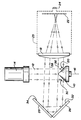
- the figure is a side, schematic view illustrating the apparatus and method according to the present invention by which the included angle of a reflective cone between opposite sides of the cone may be measured.
- a means for illuminating the curved surface of the reflective cone with a collimated beam of light 12, preferably a beam of laser light, includes a laser source 14.
- the beam of light 12 is generally parallel to the axis of said cone, indicated by dashed line 16.
- a lens means, including lens 18, receives directly a portion of the light reflected from a first side or conical sector 20 of the cone 10, and focuses the portion of the light so received in a reference plane in which is positioned reticle screen 22.
- An eyepiece 24 is provided for viewing the reticle screen.
- the lens 18, reticle screen 22 and eyepiece 24 may advantageously form a part of a measuring telescope or an auto-collimator 25. It will be appreciated that the rays of light intercepted by the lens 18 diverge in a direction normal to the plane of the figure. As a consequence, the rays will be focused as a line across the reticle screen 22 which also extends generally normal to the plane of the figure.
- a retro-reflective means including a pair of mirrors 26 and 28, is positioned on the side of the cone opposite the lens 18, for receiving directly a portion of the light reflected from a second side or conical sector 30 of the cone and redirecting the light to the lens 18.
- the second side 30 of the cone 10 is directly opposite the first side 20 of the cone.
- the pair of mirrors 26 and 28 is oriented so as to reflect light received from the cone 10 to the lens 18 along a path which is generally parallel to the path of the light received from the second side 30 of the cone, but offset with respect thereto, such that the light reflected from the retro-reflective means to the lens does not strike the cone.
- the light rays traveling from the mirror 28 to the lens 18 have directional components in the plane of the figure which are parallel to the directional components in the plane of the figure of these rays as they travel from side 30 of cone 10 to mirror 26.
- the mirrors 26 and 28 have their mirrored surfaces 32 and 34, respectively, oriented at a ninety degree included angle so as to provide retro-reflection.
- the mirror 26 intercepts diverging rays which are reflected from the curved reflective surface of the cone 10.
- the divergence of the rays in a direction normal to the plane of the figure continues as the rays are reflected by the mirrors 26 and 28 and travel to the lens 18.
- the mirrors provide retro-reflection of the rays of light in the plane of the figure, a plane which is normal to the reflective surfaces 32 and 34.
- the rays of light received by lens 18 from mirror 28 diverge in a direction normal to the plane of the figure.
- these rays will also be focused as a line across the reticle screen 22 which extends generally normal to the plane of the figure.
- the reticle screen 22 provides a light detection means at the focal point of the lens 18 for displaying the light received by the lens. It has been found that the spacing between the light received from the retro-reflective mirrors 26 and 28 and the light received directly from the side 20 of cone 10 is related to the included angle between the first and second sides 20 and 30 of the reflective cone 10. The included angle is equal to ninety degrees minus one half the angle of divergence between the light reflected by the first side of the cone and the light reflected from the retro-reflective means. Thus, if rays 36 and 38 diverge in the plane of the figure by 1 degree, the included angle is measured as 89.5 degrees. Similarly, if rays 36 and 38 converge in the plane of the figure by 1 degree, the included angle is measured as 90.5 degrees.
- the spacing in the reference plane defined by the reticle screen 22 between the light received from the retro-reflective mirrors 26 and 28 and the light received directly from the cone 10 is equal to the angle of divergence or convergence multiplied by the focal length of the lens 18.
- a measurement may be made which permits ready calculation of the included angle of the cone. If there is a question as to whether the rays 36 and 38 are converging or diverging, one may simply block off one of the two light paths momentarily so as to identify the source of the lines of light which are focused on the screen 22.
- the apparatus and method of the present invention provide a simple and reliable way of measuring the included angle of a reflective cone.
- This approach is relatively insensitive to alignment of the cone with respect to the test apparatus. If the cone is tipped slightly out of its desired orientation, the result is a slight movement of the lines of light on reticle screen 22. Since both lines move together with the distance between them remaining constant, however, the measurement process is unaffected.
- the cone 10 may be rotated about its axis 16 and additional measurements made. This may be facilitated, if desired, by providing a rotary support for the cone.
Landscapes
- Physics & Mathematics (AREA)
- General Physics & Mathematics (AREA)
- Length Measuring Devices By Optical Means (AREA)
- Testing Of Optical Devices Or Fibers (AREA)
Description
- The present invention relates to an apparatus and method for checking a reflective cone and, more particularly, to such an apparatus and method in which the included angle between opposite sides of the curved surface of the reflective cone are measured.
- Reflectors in a conical shape have utility in various optical systems. Such a reflector has a reflective, curved surface which may be used to reflect a beam of light. When the beam is generally aligned with the axis of the cone and directed so as to strike cone at its apex and on the curved surface surrounding the apex, the beam is reflected radially outward from the axis of the cone. If the included angle between opposite sides of the cone is ninety degrees, the beam is reflected radially outward in a plane. For example, a laser beam may thus be reflected into a plane which provides a continuous reference level over a construction site.
- A laser beam transmitter which utilizes a similar conical reflector is shown in U.S. Patent No. 4,679,937, issued July 4, 1987, to Cain et al, and assigned to the assignee of the present invention. The Cain et al transmitter provides a conical reflector having an included angle which is slightly less than ninety degrees. The laser light beam travels upward, striking the reflector and being reflected into a slightly upwardly directed conical shape. This is more than compensated by refraction of a surrounding glass housing, however, so as to produce a cone of laser light which is directed slightly downward. The purpose of this slight downward tilt to the reference cone of light is to compensate in part for the curvature of the earth over relatively large construction sites.
- A principle problem which exists in the production of conical reflectors, regardless of the angle of the apex of such reflectors, is the difficulty in testing the reflectors for conformity to design specifications. This difficulty is due to the curved shape of the surface being measured and to the narrow tolerances to which reflectors must be constructed for some applications. It will be appreciated that if the transmitter using the reflector has an operating range of 1000 feet, even a very small deviation in the angular orientation of the reflective surface produces an appreciable and unacceptable error in the position of the reference light plane at the more remote points of the construction site. While some test fixtures have been developed in the past for testing conical reflectors, such test fixtures have been difficult to set up and time consuming to use.
- It is seen that there is a need, therefore, for an apparatus and method for measuring the included angle of a reflective cone between opposite sides of the cone, in which the measurement process can be effected quickly and accurately.
- This need is meet by an apparatus and method according to the present invention as claimed in
claims 1 and 11 for measuring the included angle of a reflective cone between opposite sides of the reflective cone. The apparatus includes means for illuminating the curved surface of the reflective cone with a collimated beam of light, the beam of light being generally parallel to the axis of the cone. A lens means receives directly a portion of the light reflected from a first side of the cone, and focuses the portion of the light so received in a reference plane. A retro-reflective means, positioned on the side of the cone opposite the lens means, receives directly a portion of the light reflected from a second side of the cone and redirects the light to the lens means in a direction parallel to the light reflected from the second side of the cone. The second side of the cone is opposite to the first side of the cone. A light detection means at the focal point of the lens means displays the light received by the lens means, whereby the spacing between the light received from the retro-reflective means and the light received directly from the cone is related to the included angle between the first and second sides of the reflective cone. - The retro-reflective means may comprise a pair of mirrors having their mirrored surfaces oriented at a 90 degree included angle. The light detection means may comprise a screen. The pair of mirrors in the retro-reflective means may be oriented so as to reflect light received from the cone to the lens means along a path which is parallel to the path of the light received from the second side of the cone, but offset with respect thereto, such that the light reflected from the retro-reflective means to the lens means does not strike the cone.
- The light detection means at the focal point of the lens means for displaying the light received by the lens means may comprise a reticle screen in the plane. An eyepiece may be provided for viewing the reticle screen. The means for illuminating the curved surface of the reflective cone with a collimated beam of light may comprise a source of laser light. The included angle is equal to ninety degrees minus one half the angle of divergence between the light reflected by the first side of the cone and the light reflected from the retro-reflective means.
- The spacing in the reference plane between the light received from the retro-reflective means and the light received directly from the cone is equal to the angle of divergence multiplied by the focal length of the lens means. The lens means and the light detection means comprise portions of an auto-collimator.
- A method for measuring the included angle of a reflective cone between opposite, first and second sides of a reflective cone, comprise the steps of:
- a.) illuminating the curved surface of the reflective cone with a collimated beam of light, the beam of light being generally parallel to the axis of the cone;
- b.) receiving a portion of the light reflected from the second side of the cone and redirecting the light in a direction parallel to the light reflected from the second side of the cone;
- c.) positioning a lens so as to focus in a reference plane a portion of the light reflected from a first side of the cone, and a portion of the redirected light from the second side of the cone; and
- d.) displaying in the reference plane the light received by the lens, whereby the spacing between the light received from the first and second sides of the cone is related to the included angle.
- The step of receiving and redirecting a portion of the light reflected from the second side of the cone is accomplished by means of a pair of mirrors having their mirrored surfaces oriented at a 90 degree included angle. The step of displaying includes the step of displaying the light on a screen. The pair of mirrors are oriented so as to reflect light received from the cone to the lens along a path which is parallel to the path of the light received from the second side of the cone, but offset with respect thereto, such that the light reflected from the mirrors to the lens does not strike the cone. A reticle screen is positioned in the plane, and an eyepiece is provided for viewing the reticle screen.
- The collimated beam of light may comprise a beam of laser light. The included angle may be equal to ninety degrees minus one half the angle of divergence between the light reflected by the first side of the cone and the light reflected from the second side of the cone and subsequently redirected. The spacing in the reference plane between the light received from the first and second sides of the cone is equal to the angle of divergence multiplied by the focal length of the lens. The lens may form a portion of an auto-collimator.
- Accordingly, it is an object of the present invention to provide an improved apparatus and method for measuring the included angle between two sides of a reflective cone; to provide such an apparatus and method in which the measurement process is relatively insensitive to errors in the orientation of the reflective cone with respect to the direction of the illuminating collimated light beam; to provide such an apparatus and method in which the measurement process is relatively insensitive to mechanical instability of the measurement apparatus; and to provide such an apparatus and method in which a reflective cone may be check easily, simply and quickly for a desired uniform, curved, reflective surface.
- Other objects and advantages of the invention will be apparent from the following description, the accompanying drawing and the appended claims.
- In order that the invention may be more readily understood, reference will now be made by example to the accompanying drawings in which:
- The figure is a side, schematic view illustrating the apparatus and method according to the present invention by which the included angle of a reflective cone between opposite sides of the cone may be measured.
- Reference is made to the figure which illustrates apparatus constructed according to the present invention for measuring the included angle of a reflective cone 10 between opposite sides of the cone. A means for illuminating the curved surface of the reflective cone with a collimated beam of light 12, preferably a beam of laser light, includes a
laser source 14. The beam of light 12 is generally parallel to the axis of said cone, indicated by dashedline 16. A lens means, includinglens 18, receives directly a portion of the light reflected from a first side orconical sector 20 of the cone 10, and focuses the portion of the light so received in a reference plane in which is positionedreticle screen 22. An eyepiece 24 is provided for viewing the reticle screen. Thelens 18,reticle screen 22 and eyepiece 24 may advantageously form a part of a measuring telescope or an auto-collimator 25. It will be appreciated that the rays of light intercepted by thelens 18 diverge in a direction normal to the plane of the figure. As a consequence, the rays will be focused as a line across thereticle screen 22 which also extends generally normal to the plane of the figure. - A retro-reflective means, including a pair of
mirrors lens 18, for receiving directly a portion of the light reflected from a second side orconical sector 30 of the cone and redirecting the light to thelens 18. Thesecond side 30 of the cone 10 is directly opposite thefirst side 20 of the cone. The pair ofmirrors lens 18 along a path which is generally parallel to the path of the light received from thesecond side 30 of the cone, but offset with respect thereto, such that the light reflected from the retro-reflective means to the lens does not strike the cone. - The light rays traveling from the
mirror 28 to thelens 18 have directional components in the plane of the figure which are parallel to the directional components in the plane of the figure of these rays as they travel fromside 30 of cone 10 tomirror 26. Themirrors surfaces - It will be appreciated that the
mirror 26 intercepts diverging rays which are reflected from the curved reflective surface of the cone 10. The divergence of the rays in a direction normal to the plane of the figure continues as the rays are reflected by themirrors lens 18. The mirrors provide retro-reflection of the rays of light in the plane of the figure, a plane which is normal to thereflective surfaces lens 18 fromside 20, the rays of light received bylens 18 frommirror 28 diverge in a direction normal to the plane of the figure. As a consequence, these rays will also be focused as a line across thereticle screen 22 which extends generally normal to the plane of the figure. - The
reticle screen 22 provides a light detection means at the focal point of thelens 18 for displaying the light received by the lens. It has been found that the spacing between the light received from the retro-reflective mirrors side 20 of cone 10 is related to the included angle between the first andsecond sides rays 36 and 38 diverge in the plane of the figure by 1 degree, the included angle is measured as 89.5 degrees. Similarly, ifrays 36 and 38 converge in the plane of the figure by 1 degree, the included angle is measured as 90.5 degrees. - The spacing in the reference plane defined by the
reticle screen 22 between the light received from the retro-reflective mirrors lens 18. As a consequence, by merely observing thescreen 22 through the eyepiece 24, a measurement may be made which permits ready calculation of the included angle of the cone. If there is a question as to whether therays 36 and 38 are converging or diverging, one may simply block off one of the two light paths momentarily so as to identify the source of the lines of light which are focused on thescreen 22. - It will be appreciated that if retro-
reflective mirrors mirror 28 to thelens 18 will have directional components in the plane of the figure which are not precisely parallel to the directional components in the plane of the figure of these rays as they travel fromside 30 of cone 10 to mirror 26. This is acceptable, provided an appropriate correction is made in the angle measured by means oflens 18 andreticle 22. - It has been found that the apparatus and method of the present invention provide a simple and reliable way of measuring the included angle of a reflective cone. This approach is relatively insensitive to alignment of the cone with respect to the test apparatus. If the cone is tipped slightly out of its desired orientation, the result is a slight movement of the lines of light on
reticle screen 22. Since both lines move together with the distance between them remaining constant, however, the measurement process is unaffected. It will be appreciated that the cone 10 may be rotated about itsaxis 16 and additional measurements made. This may be facilitated, if desired, by providing a rotary support for the cone.
Claims (20)
Applications Claiming Priority (2)
| Application Number | Priority Date | Filing Date | Title |
|---|---|---|---|
| US07/090,944 US4758729A (en) | 1987-08-28 | 1987-08-28 | Apparatus and method for measuring the included angle of a reflective cone |
| US90944 | 1987-08-28 |
Publications (3)
| Publication Number | Publication Date |
|---|---|
| EP0305182A2 EP0305182A2 (en) | 1989-03-01 |
| EP0305182A3 EP0305182A3 (en) | 1989-05-31 |
| EP0305182B1 true EP0305182B1 (en) | 1991-11-06 |
Family
ID=22225057
Family Applications (1)
| Application Number | Title | Priority Date | Filing Date |
|---|---|---|---|
| EP88307887A Expired EP0305182B1 (en) | 1987-08-28 | 1988-08-25 | Apparatus and method for measuring reflective cone |
Country Status (4)
| Country | Link |
|---|---|
| US (1) | US4758729A (en) |
| EP (1) | EP0305182B1 (en) |
| JP (1) | JPH01131407A (en) |
| DE (1) | DE3866067D1 (en) |
Families Citing this family (30)
| Publication number | Priority date | Publication date | Assignee | Title |
|---|---|---|---|---|
| IT1235330B (en) * | 1989-01-30 | 1992-06-26 | Aeroel Di Spizzamiglio Ing A & | SYSTEM FOR THE AUTOMATIC COMPENSATION OF THE TRANSVERSAL OSCILLATION OF THE SCANNING PLANE IN A LASER LIGHT PROFILE GAUGE, OBTAINED THROUGH A SPECIAL DEVICE |
| DE3933057A1 (en) * | 1989-10-04 | 1991-04-18 | Doerries Scharmann Gmbh | METHOD AND DEVICE FOR DETERMINING THE POSITION AND DIAMETER OF THE FOCUS (FOCUS) OF A LASER BEAM, ESPECIALLY FOR USE FOR THE PROCESSING OF MATERIALS WITH A HIGH-PERFORMANCE LASER BEAM |
| EP2264428B1 (en) | 1997-01-31 | 2017-05-03 | Xy, Llc | Optical apparatus with focussing reflector for converging radiation onto a flow of particles |
| TW409183B (en) * | 1997-06-25 | 2000-10-21 | Hosokawa Micron Kk | The method and the device for measuring the inclination angle of powder/grain material stack |
| US6149867A (en) | 1997-12-31 | 2000-11-21 | Xy, Inc. | Sheath fluids and collection systems for sex-specific cytometer sorting of sperm |
| US6248590B1 (en) | 1998-02-27 | 2001-06-19 | Cytomation, Inc. | Method and apparatus for flow cytometry |
| NZ509434A (en) | 1998-07-30 | 2004-03-26 | Univ Colorado State Res Found | Equine system for non-surgical artificial insemination |
| US7024316B1 (en) * | 1999-10-21 | 2006-04-04 | Dakocytomation Colorado, Inc. | Transiently dynamic flow cytometer analysis system |
| US7208265B1 (en) | 1999-11-24 | 2007-04-24 | Xy, Inc. | Method of cryopreserving selected sperm cells |
| SE517696C2 (en) * | 2000-02-08 | 2002-07-02 | Saab Ab | Laser device |
| EP2258169B1 (en) | 2000-05-09 | 2019-07-10 | Xy, Llc | Method for isolating X-chromosome bearing and Y-chromosome bearing populations of spermatozoa |
| US7713687B2 (en) | 2000-11-29 | 2010-05-11 | Xy, Inc. | System to separate frozen-thawed spermatozoa into x-chromosome bearing and y-chromosome bearing populations |
| AU2002237689B2 (en) | 2000-11-29 | 2008-01-10 | Xy, Llc. | System to separate frozen-thawed spermatozoa into X-chromosome bearing and Y-chromosome bearing populations |
| US7012689B2 (en) | 2001-05-17 | 2006-03-14 | Dako Colorado, Inc. | Flow cytometer with active automated optical alignment system |
| US20030211009A1 (en) * | 2001-05-18 | 2003-11-13 | Buchanan Kris S. | Rapid multi-material sample input system |
| US8486618B2 (en) | 2002-08-01 | 2013-07-16 | Xy, Llc | Heterogeneous inseminate system |
| WO2004012837A2 (en) | 2002-08-01 | 2004-02-12 | Xy, Inc. | Low pressure sperm cell separation system |
| BRPI0313476B1 (en) | 2002-08-15 | 2015-06-23 | Xy Llc | High resolution flow cytometer |
| US7169548B2 (en) | 2002-09-13 | 2007-01-30 | Xy, Inc. | Sperm cell processing and preservation systems |
| MX345106B (en) | 2003-03-28 | 2017-01-16 | Inguran Llc * | Apparatus, methods and processes for sorting particles and for providing sex-sorted animal sperm. |
| CA2566749C (en) | 2003-05-15 | 2017-02-21 | Xy, Inc. | Efficient haploid cell sorting for flow cytometer systems |
| EP2260854A1 (en) | 2004-03-29 | 2010-12-15 | Inguran, LLC | Sperm suspensions for sorting into x or y chromosome-bearing enriched populations |
| EP2269617B1 (en) | 2004-07-22 | 2016-04-27 | Inguran, LLC | Process for enriching a population of sperm cells |
| WO2006015056A2 (en) | 2004-07-27 | 2006-02-09 | Dakocytomation Denmarks A/S | Enhancing flow cytometry discrimination with geometric transformation |
| US7618770B2 (en) | 2005-07-29 | 2009-11-17 | Xy, Inc. | Methods and apparatus for reducing protein content in sperm cell extenders |
| DE102006022894A1 (en) * | 2006-05-15 | 2007-11-22 | J & M Analytische Mess- Und Regeltechnik Gmbh | Device for determining certain properties of a pourable product |
| US9157734B2 (en) * | 2012-06-15 | 2015-10-13 | Bae Systems Information And Electronic Systems Integration Inc. | Optical automatic attitude measurement for lightweight portable optical systems |
| AT515521B1 (en) * | 2014-07-23 | 2015-10-15 | Trumpf Maschinen Austria Gmbh | Bending angle measuring device and method for measuring a bending angle by means of the bending angle measuring device |
| CN104359872A (en) * | 2014-11-05 | 2015-02-18 | 上海启济科技有限公司 | Device for measuring wavelength transmittance |
| CN114235357B (en) * | 2022-02-25 | 2022-06-07 | 茂莱(南京)仪器有限公司 | Dihedral angle reflector folding optical system for full-field sampling detection |
Family Cites Families (7)
| Publication number | Priority date | Publication date | Assignee | Title |
|---|---|---|---|---|
| GB1063873A (en) * | 1962-09-14 | 1967-03-30 | Secr Aviation | Optical measuring apparatus |
| US3419329A (en) * | 1964-01-02 | 1968-12-31 | Nasa Usa | Combined optical attitude and altitude indicating instrument |
| US3527953A (en) * | 1966-12-28 | 1970-09-08 | Optomechanisms Inc | Photoelectric line detector |
| JPS5361356A (en) * | 1976-11-15 | 1978-06-01 | Fujitsu Ltd | Minute angle measuring device |
| JPS5512483A (en) * | 1978-07-13 | 1980-01-29 | Sumitomo Special Metals Co Ltd | Right angle measurement |
| JPS60152929A (en) * | 1984-01-23 | 1985-08-12 | Fuji Xerox Co Ltd | Divided-angle-error measuring apparatus of polygon mirror |
| US4679937A (en) * | 1985-10-18 | 1987-07-14 | Spectra-Physics, Inc. | Self leveling transmitter for laser alignment systems |
-
1987
- 1987-08-28 US US07/090,944 patent/US4758729A/en not_active Expired - Fee Related
-
1988
- 1988-08-17 JP JP63204548A patent/JPH01131407A/en active Pending
- 1988-08-25 EP EP88307887A patent/EP0305182B1/en not_active Expired
- 1988-08-25 DE DE8888307887T patent/DE3866067D1/en not_active Expired - Lifetime
Also Published As
| Publication number | Publication date |
|---|---|
| JPH01131407A (en) | 1989-05-24 |
| DE3866067D1 (en) | 1991-12-12 |
| US4758729A (en) | 1988-07-19 |
| EP0305182A2 (en) | 1989-03-01 |
| EP0305182A3 (en) | 1989-05-31 |
Similar Documents
| Publication | Publication Date | Title |
|---|---|---|
| EP0305182B1 (en) | Apparatus and method for measuring reflective cone | |
| CN1071898C (en) | Measuring ball reflector | |
| CA1219477A (en) | Penta-prism module having laser alignment error detection and correction capability | |
| EP0327072A2 (en) | Boresight alignment measuring apparatus and method for electro-optic systems | |
| JPH039402B2 (en) | ||
| EP0626561B1 (en) | Automatic inclination angle compensator | |
| CN110207588A (en) | A kind of prism of corner cube optical apex sighting device and its Method of Adjustment | |
| CN109358435B (en) | Device and method for adjusting perpendicularity of double telecentric lenses | |
| US4433894A (en) | Method and apparatus for generating optical scans | |
| US4346994A (en) | Secondary alignment target for an electro-optical alignment measuring system | |
| US5506675A (en) | Laser target designator tester for measuring static and dynamic error | |
| CN105737759A (en) | Long trace profile measurement device | |
| CN111426449A (en) | Method for calibrating parallelism of optical axes of multiple autocollimators | |
| CN105737758B (en) | A kind of long-range profile measuring instrument | |
| CN105758333A (en) | Long-trace optical surface profile detector | |
| CN109212775A (en) | A kind of bio-measurement instrument zero point arm debugging apparatus and method | |
| WO2001004572A1 (en) | Laser reflector alignment | |
| US4595288A (en) | Method and apparatus for measuring deep mirrors | |
| CN105674913A (en) | Detection system for long-range optical surface profile | |
| US5764349A (en) | Self-aligning baseline plane instrument | |
| JP7502749B2 (en) | Surveying method using surveying targets and total stations | |
| US4624527A (en) | Radiation-utilizing measurement system | |
| JP2783252B2 (en) | Angle difference measuring device between two surfaces | |
| JPH0451995B2 (en) | ||
| SU916974A1 (en) | Device for checking levels |
Legal Events
| Date | Code | Title | Description |
|---|---|---|---|
| PUAI | Public reference made under article 153(3) epc to a published international application that has entered the european phase |
Free format text: ORIGINAL CODE: 0009012 |
|
| AK | Designated contracting states |
Kind code of ref document: A2 Designated state(s): DE FR GB NL SE |
|
| PUAL | Search report despatched |
Free format text: ORIGINAL CODE: 0009013 |
|
| AK | Designated contracting states |
Kind code of ref document: A3 Designated state(s): DE FR GB NL SE |
|
| 17P | Request for examination filed |
Effective date: 19890918 |
|
| 17Q | First examination report despatched |
Effective date: 19900621 |
|
| GRAA | (expected) grant |
Free format text: ORIGINAL CODE: 0009210 |
|
| RAP1 | Party data changed (applicant data changed or rights of an application transferred) |
Owner name: SPECTRA-PHYSICS LASERPLANE, INC. |
|
| AK | Designated contracting states |
Kind code of ref document: B1 Designated state(s): DE FR GB NL SE |
|
| REF | Corresponds to: |
Ref document number: 3866067 Country of ref document: DE Date of ref document: 19911212 |
|
| EN | Fr: translation not filed | ||
| ET | Fr: translation filed |
Free format text: BO 13/92 PAGE 169: ANNULATION |
|
| ET | Fr: translation filed | ||
| PLBE | No opposition filed within time limit |
Free format text: ORIGINAL CODE: 0009261 |
|
| STAA | Information on the status of an ep patent application or granted ep patent |
Free format text: STATUS: NO OPPOSITION FILED WITHIN TIME LIMIT |
|
| 26N | No opposition filed | ||
| PGFP | Annual fee paid to national office [announced via postgrant information from national office to epo] |
Ref country code: FR Payment date: 19940712 Year of fee payment: 7 |
|
| PGFP | Annual fee paid to national office [announced via postgrant information from national office to epo] |
Ref country code: GB Payment date: 19940728 Year of fee payment: 7 |
|
| PGFP | Annual fee paid to national office [announced via postgrant information from national office to epo] |
Ref country code: SE Payment date: 19940831 Year of fee payment: 7 Ref country code: NL Payment date: 19940831 Year of fee payment: 7 |
|
| EAL | Se: european patent in force in sweden |
Ref document number: 88307887.5 |
|
| PG25 | Lapsed in a contracting state [announced via postgrant information from national office to epo] |
Ref country code: GB Effective date: 19950825 |
|
| PG25 | Lapsed in a contracting state [announced via postgrant information from national office to epo] |
Ref country code: SE Effective date: 19950826 |
|
| PG25 | Lapsed in a contracting state [announced via postgrant information from national office to epo] |
Ref country code: NL Effective date: 19960301 |
|
| GBPC | Gb: european patent ceased through non-payment of renewal fee |
Effective date: 19950825 |
|
| PG25 | Lapsed in a contracting state [announced via postgrant information from national office to epo] |
Ref country code: FR Effective date: 19960430 |
|
| NLV4 | Nl: lapsed or anulled due to non-payment of the annual fee |
Effective date: 19960301 |
|
| EUG | Se: european patent has lapsed |
Ref document number: 88307887.5 |
|
| REG | Reference to a national code |
Ref country code: FR Ref legal event code: ST |
|
| PGFP | Annual fee paid to national office [announced via postgrant information from national office to epo] |
Ref country code: DE Payment date: 19960716 Year of fee payment: 9 |
|
| PG25 | Lapsed in a contracting state [announced via postgrant information from national office to epo] |
Ref country code: DE Free format text: LAPSE BECAUSE OF NON-PAYMENT OF DUE FEES Effective date: 19980501 |