EP0304919B1 - Stufenloses Planetengetriebe - Google Patents
Stufenloses Planetengetriebe Download PDFInfo
- Publication number
- EP0304919B1 EP0304919B1 EP88113877A EP88113877A EP0304919B1 EP 0304919 B1 EP0304919 B1 EP 0304919B1 EP 88113877 A EP88113877 A EP 88113877A EP 88113877 A EP88113877 A EP 88113877A EP 0304919 B1 EP0304919 B1 EP 0304919B1
- Authority
- EP
- European Patent Office
- Prior art keywords
- planetary gear
- actuator
- drive shaft
- drive
- planet
- Prior art date
- Legal status (The legal status is an assumption and is not a legal conclusion. Google has not performed a legal analysis and makes no representation as to the accuracy of the status listed.)
- Expired - Lifetime
Links
Images


Classifications
-
- F—MECHANICAL ENGINEERING; LIGHTING; HEATING; WEAPONS; BLASTING
- F16—ENGINEERING ELEMENTS AND UNITS; GENERAL MEASURES FOR PRODUCING AND MAINTAINING EFFECTIVE FUNCTIONING OF MACHINES OR INSTALLATIONS; THERMAL INSULATION IN GENERAL
- F16H—GEARING
- F16H3/00—Toothed gearings for conveying rotary motion with variable gear ratio or for reversing rotary motion
- F16H3/44—Toothed gearings for conveying rotary motion with variable gear ratio or for reversing rotary motion using gears having orbital motion
- F16H3/72—Toothed gearings for conveying rotary motion with variable gear ratio or for reversing rotary motion using gears having orbital motion with a secondary drive, e.g. regulating motor, in order to vary speed continuously
-
- F—MECHANICAL ENGINEERING; LIGHTING; HEATING; WEAPONS; BLASTING
- F16—ENGINEERING ELEMENTS AND UNITS; GENERAL MEASURES FOR PRODUCING AND MAINTAINING EFFECTIVE FUNCTIONING OF MACHINES OR INSTALLATIONS; THERMAL INSULATION IN GENERAL
- F16H—GEARING
- F16H47/00—Combinations of mechanical gearing with fluid clutches or fluid gearing
- F16H47/02—Combinations of mechanical gearing with fluid clutches or fluid gearing the fluid gearing being of the volumetric type
- F16H47/04—Combinations of mechanical gearing with fluid clutches or fluid gearing the fluid gearing being of the volumetric type the mechanical gearing being of the type with members having orbital motion
-
- B—PERFORMING OPERATIONS; TRANSPORTING
- B60—VEHICLES IN GENERAL
- B60K—ARRANGEMENT OR MOUNTING OF PROPULSION UNITS OR OF TRANSMISSIONS IN VEHICLES; ARRANGEMENT OR MOUNTING OF PLURAL DIVERSE PRIME-MOVERS IN VEHICLES; AUXILIARY DRIVES FOR VEHICLES; INSTRUMENTATION OR DASHBOARDS FOR VEHICLES; ARRANGEMENTS IN CONNECTION WITH COOLING, AIR INTAKE, GAS EXHAUST OR FUEL SUPPLY OF PROPULSION UNITS IN VEHICLES
- B60K6/00—Arrangement or mounting of plural diverse prime-movers for mutual or common propulsion, e.g. hybrid propulsion systems comprising electric motors and internal combustion engines ; Control systems therefor, i.e. systems controlling two or more prime movers, or controlling one of these prime movers and any of the transmission, drive or drive units Informative references: mechanical gearings with secondary electric drive F16H3/72; arrangements for handling mechanical energy structurally associated with the dynamo-electric machine H02K7/00; machines comprising structurally interrelated motor and generator parts H02K51/00; dynamo-electric machines not otherwise provided for in H02K see H02K99/00
- B60K6/08—Prime-movers comprising combustion engines and mechanical or fluid energy storing means
- B60K6/12—Prime-movers comprising combustion engines and mechanical or fluid energy storing means by means of a chargeable fluidic accumulator
-
- B—PERFORMING OPERATIONS; TRANSPORTING
- B60—VEHICLES IN GENERAL
- B60Y—INDEXING SCHEME RELATING TO ASPECTS CROSS-CUTTING VEHICLE TECHNOLOGY
- B60Y2400/00—Special features of vehicle units
- B60Y2400/15—Pneumatic energy storages, e.g. pressure air tanks
-
- F—MECHANICAL ENGINEERING; LIGHTING; HEATING; WEAPONS; BLASTING
- F16—ENGINEERING ELEMENTS AND UNITS; GENERAL MEASURES FOR PRODUCING AND MAINTAINING EFFECTIVE FUNCTIONING OF MACHINES OR INSTALLATIONS; THERMAL INSULATION IN GENERAL
- F16H—GEARING
- F16H37/00—Combinations of mechanical gearings, not provided for in groups F16H1/00 - F16H35/00
- F16H37/02—Combinations of mechanical gearings, not provided for in groups F16H1/00 - F16H35/00 comprising essentially only toothed or friction gearings
- F16H37/06—Combinations of mechanical gearings, not provided for in groups F16H1/00 - F16H35/00 comprising essentially only toothed or friction gearings with a plurality of driving or driven shafts; with arrangements for dividing torque between two or more intermediate shafts
- F16H37/08—Combinations of mechanical gearings, not provided for in groups F16H1/00 - F16H35/00 comprising essentially only toothed or friction gearings with a plurality of driving or driven shafts; with arrangements for dividing torque between two or more intermediate shafts with differential gearing
- F16H37/0833—Combinations of mechanical gearings, not provided for in groups F16H1/00 - F16H35/00 comprising essentially only toothed or friction gearings with a plurality of driving or driven shafts; with arrangements for dividing torque between two or more intermediate shafts with differential gearing with arrangements for dividing torque between two or more intermediate shafts, i.e. with two or more internal power paths
- F16H37/084—Combinations of mechanical gearings, not provided for in groups F16H1/00 - F16H35/00 comprising essentially only toothed or friction gearings with a plurality of driving or driven shafts; with arrangements for dividing torque between two or more intermediate shafts with differential gearing with arrangements for dividing torque between two or more intermediate shafts, i.e. with two or more internal power paths at least one power path being a continuously variable transmission, i.e. CVT
- F16H2037/0866—Power split variators with distributing differentials, with the output of the CVT connected or connectable to the output shaft
- F16H2037/0873—Power split variators with distributing differentials, with the output of the CVT connected or connectable to the output shaft with switching, e.g. to change ranges
-
- F—MECHANICAL ENGINEERING; LIGHTING; HEATING; WEAPONS; BLASTING
- F16—ENGINEERING ELEMENTS AND UNITS; GENERAL MEASURES FOR PRODUCING AND MAINTAINING EFFECTIVE FUNCTIONING OF MACHINES OR INSTALLATIONS; THERMAL INSULATION IN GENERAL
- F16H—GEARING
- F16H37/00—Combinations of mechanical gearings, not provided for in groups F16H1/00 - F16H35/00
- F16H37/02—Combinations of mechanical gearings, not provided for in groups F16H1/00 - F16H35/00 comprising essentially only toothed or friction gearings
- F16H37/06—Combinations of mechanical gearings, not provided for in groups F16H1/00 - F16H35/00 comprising essentially only toothed or friction gearings with a plurality of driving or driven shafts; with arrangements for dividing torque between two or more intermediate shafts
- F16H37/08—Combinations of mechanical gearings, not provided for in groups F16H1/00 - F16H35/00 comprising essentially only toothed or friction gearings with a plurality of driving or driven shafts; with arrangements for dividing torque between two or more intermediate shafts with differential gearing
- F16H37/0833—Combinations of mechanical gearings, not provided for in groups F16H1/00 - F16H35/00 comprising essentially only toothed or friction gearings with a plurality of driving or driven shafts; with arrangements for dividing torque between two or more intermediate shafts with differential gearing with arrangements for dividing torque between two or more intermediate shafts, i.e. with two or more internal power paths
- F16H37/084—Combinations of mechanical gearings, not provided for in groups F16H1/00 - F16H35/00 comprising essentially only toothed or friction gearings with a plurality of driving or driven shafts; with arrangements for dividing torque between two or more intermediate shafts with differential gearing with arrangements for dividing torque between two or more intermediate shafts, i.e. with two or more internal power paths at least one power path being a continuously variable transmission, i.e. CVT
- F16H2037/088—Power split variators with summing differentials, with the input of the CVT connected or connectable to the input shaft
- F16H2037/0886—Power split variators with summing differentials, with the input of the CVT connected or connectable to the input shaft with switching means, e.g. to change ranges
-
- Y—GENERAL TAGGING OF NEW TECHNOLOGICAL DEVELOPMENTS; GENERAL TAGGING OF CROSS-SECTIONAL TECHNOLOGIES SPANNING OVER SEVERAL SECTIONS OF THE IPC; TECHNICAL SUBJECTS COVERED BY FORMER USPC CROSS-REFERENCE ART COLLECTIONS [XRACs] AND DIGESTS
- Y02—TECHNOLOGIES OR APPLICATIONS FOR MITIGATION OR ADAPTATION AGAINST CLIMATE CHANGE
- Y02T—CLIMATE CHANGE MITIGATION TECHNOLOGIES RELATED TO TRANSPORTATION
- Y02T10/00—Road transport of goods or passengers
- Y02T10/60—Other road transportation technologies with climate change mitigation effect
- Y02T10/62—Hybrid vehicles
Definitions
- the object of the patent is to design the planetary gear of a hybrid drive device in such a way that, in the case of strongly changing operating conditions, the force flow in the drive system is only possible with mechanical components.
- This object is achieved by the features of the planetary gear proposed in claim 1.
- Advantageous designs of the planetary gear according to the main claim are dealt with in the subclaims.
- the planetary gear has one planetary gear set each for forward and reverse operation.
- the area of application of the transmission can be expanded with several planetary gear sets.
- the gear works like a conventional planetary gear, but with the crucial difference that the fixed element is a mechanically, hydraulically, pneumatically or electrically adjustable actuator.
- the regulation of the actuator creates a stepless output that is independent of the drive of the planetary gear set.
- the following explanations are limited to the single-stage planetary gear sets.
- the planetary gear set is mechanically driven directly by the drive motor, for example an internal combustion engine.
- the actuator of the planetary gear set is adjustable in its circumferential speed in both directions of rotation by an actuator.
- the actuator is thus regulated by one of the media mentioned above, the energy and conversion of which is fed by the combustion engine. Either the energy for regulating the actuator is transmitted directly through the medium or by interposing an energy store.
- the combustion engine, the energy converter, the actuator and the energy store (s) are regulated with a control unit.
- the control unit receives the commands from electronics that evaluate and monitor all pending characteristic data and operating instructions.
- Energy is generated during braking and fed into the drive system. This energy is used to regulate the actuator up to switching off the combustion engine.
- the information for the anti-lock behavior and for the anti-slip control are passed on to the control unit.
- the system is operated, for example, with a lever arranged below the steering wheel, similar to the known retarder controls.
- the system can be supplemented with a generator.
- the electrical energy generated is stored or fed to the travel drive. With the electrical energy, water can be broken down into hydrogen and oxygen while driving.
- the fuel thus obtained is used to operate an environmentally friendly hydrogen engine instead of the combustion engine (diesel or petrol).
- a rotary piston compressor / rotary piston motor can be used instead of the compressor turbine wheel.
- vacuum accumulators can also be used as energy accumulators instead of the pressure accumulators.
- the construction of the planetary gear can be simplified and the control can be reduced to one actuator.
- the combustion engine can be operated constantly in the most economical range and can be brought to nominal speeds with the lock-up clutches closed.
- hydraulic pumps and hydraulic motors as one element can combine both functions of generating or consuming energy. This can simplify the structure in certain cases. This applies to the electric motor and generator.
- the units arranged on the primary drive shaft can be equipped with a switchable fan wheel, which ensures the cooling of these and subsequent units.
- All components of the drive system are designed to be switchable, but they are only connected when required and for reasons of economy, using a positive connection be involved. Depending on the required application, these connections can be made or carried out mechanically, hydraulically, electrohydraulically, electrically or in combination.
- the double-flow pump on the primary drive shaft can be operated so that one circuit is firmly connected to the primary drive shaft, the second circuit can be switched on and off. Or both circuits are firmly connected to the primary drive shaft or both circuits can be switched.
- the energy, e.g. for the electromagnetic clutches can be fetched from the main drive motor.
- the stored electrical energy could be used to generate hydrogen or support superconductivity.
- a major advantage of all conceivable systems is the ability to close and open couplings without load and jerk.
- the coupling process is only carried out when the speed of the driving and driving unit in the system is the same. Since the speed compensation is first established and then the connection is established, the power flow is maintained. This method of operation means that the couplings incorporated in the system will have a long service life.
- the different pressure in the individual energy stores can be reduced to a common mean value by means of an automatic device when the transmission is stationary for a longer period.
- One or more power take-offs with different ratios, output torques or directions of rotation can be arranged anywhere on the primary or secondary drive shaft in the system presented.
- the power take-offs are also switchable at the output point.
- the additional devices of the systems presented are each switchable so that they are only in operation when needed and cannot generate power losses.
- the purpose of the gearbox designs presented is the automatic regulation of the speed and the power at the output.
- the drive motor operates at a constant speed in the optimum of its map.
- the various load cases for the vehicle, driving speed and driving resistance can be regulated automatically or by user intervention depending on the need and range of services.
- the actuators of the planetary gear sets can be accelerated or decelerated in such a way that the bridging points in between are not used.
- Hydraulic motors and pumps can have different designs, such as tooth shape, rotor shape, rotary piston shape, cam disc shape, wing shape.
- the selection will be based on the state of the art or the offer of the industry.
- the planetary gear set forward and the planet gear set reverse are simultaneously switched either hydraulically or purely mechanically. In this state, the planetary gear is blocked.
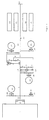
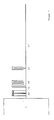
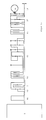
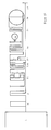
- FIG. 1 shows the transmission
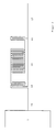
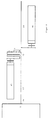
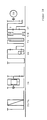
- Figure 2 shows the drive shaft of the transmission with clutches.
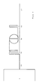
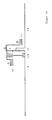
- Figure 3 shows the drive shaft of the transmission with clutches and a torque converter.
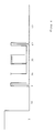
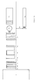
- Figure 4 shows the drive shaft of the transmission with clutches and a hydraulic motor.
- Figure 5 shows the drive shaft of the transmission with clutches, a planetary gear with lockup clutch, with an actuator and a hydraulic motor.
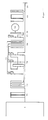
- Figure 6 shows, like Figure 7, the drive shaft train of the transmission according to the previous figures with additional hydraulic pumps.
- FIG. 8 shows the arrangement of energy stores on the drive shaft train.
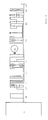
- Figure 9 shows the transmission with electrical control and electrical energy storage.
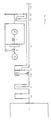
- FIG. 10 shows the transmission with an expanded drive shaft train to which an electric motor is assigned.
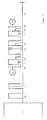
- Figure 11 shows a multi-stage planetary gear.
- Figure 12 shows a Einste planetary gear.
- Figure 13 shows the transmission with an upstream multi-stage planetary gear.
- Figure 14 shows the transmission with a downstream multi-planetary gear.
- Figures 15 and 16 show the planetary gear with constant operation of the drive motor.
- Figure 17 shows the actuator drive with a torque converter in the planetary gear.
- Figure 18 shows an actuator drive with a high-performance drive.
- Figure 19 shows an actuator drive with a variable actuator arm.
- Figure 20 shows the transmission with decoupled drive and direct drive.
- the combustion engine (1) with flywheel and vibration damper is followed by a safety multi-plate clutch (2).
- the multi-plate clutch opens as soon as it is not acted upon by the hydraulic control system.
- the holding of the vehicle with the combustion engine, combined with an emergency circuit for the planetary gear, is not outlined.
- the sun gear (4 and 9), the power take-off (40) and the hydraulic pump (20) are driven by the gear drive shaft (3).
- the hydraulic pump (20) works against the accumulator (21 and 22).
- the stored energy is transferred via the electro-hydraulic control system to the servomotors (23 and 24), which are connected to the actuators (5 and 10).
- the pressures and speeds called up by the system regulate the actuators (5 and 10) and thus the stepless power transmission of the drives (6 and 11).
- the outputs of the planetary gear sets are connected to the gearbox output shaft (14) and to the gearbox output flange (15).
- the lock-up clutches (7 and 8) and (12 and 13) are closed and opened by the electro-hydraulic control system.
- the electronics receive the necessary impulses from the speed sensors (32 and 33) located on the gearbox input and output shaft.
- the electro-hydraulic control including electronics (30 and 31) is not shown in detail. These devices are state of the art and can be applied by the person skilled in the art to the drive system presented.
- multi-plate clutches In front of the hydraulic pumps and servomotors, multi-plate clutches (26 to 29) are placed, which allow these units to be switched on and off separately. In this way, power losses can be avoided with aggregates that rotate with empty. The power take-off can be switched on and off with the multi-plate clutch (41). While this multi-plate clutch is essential, all other multi-plate clutches are not absolutely necessary for the system to function.
- a hydraulic pump (25) driven by the transmission output shaft (14) works against the accumulators.
- the system thus has an energy recovery system including combustion engine shutdown.
- the circuit diagram is not entered in the drawing. This facility is again state of the art. When driving forward, the gear drive shaft (3), the sun gear (4) and the hydraulic pump (20) are driven.
- the power take-off (40) is ready and can be activated on request. The same conditions apply to the power take-off when reversing. As a rule, the power take-off is only required when the vehicle is stationary.
- the hydraulic pump (20) works against the accumulator (21 and 22).
- the stored energy is called up by the electro-hydraulic system (30 and 31) and transmitted to the servomotor (23).
- the servomotor (23) is connected to the actuator (5).
- the control of the actuator (5) generates the infinitely variable power transmission for the output (6) of the planetary gear set, which is firmly connected to the gearbox output shaft (14) and the output flange (15). When the fixed point is reached, the actuator (5) is bridged.
- the stored energy is called up by the electro-hydraulic control system (30 and 31) and transmitted to the servomotor (24).
- the actuator (24) is connected to the actuator (10). When the fixed point is reached, the actuator (10) is bridged. With the closed lock-up clutch (12), the power transmission is purely mechanical. To further accelerate, the lock-up clutch (12) is opened.
- the stored energy is fed to the servomotor (24) and the actuator (10) via the electro-hydraulic control.
- the planetary gear set is blocked with the lock-up clutch (13), so that a mechanical transmission would occur, but must not occur when reversing, since the block formation of the planetary gear set always results in forward driving.
- the drive shaft on the drive motor (1) is divided into two shafts.
- the primary drive shaft (16) is connected to the motor and the secondary drive shaft (17) to the planetary gear sets. Between them is a coupling (18) that connects or separates the two shafts.
- the double clutch (18) can switch the drive system on and off.
- the multi-plate friction clutch (19) can be switched on and off on the drive side by the double clutch (18) and on the driven side of the multi-plate friction clutch by the clutch (42).
- the multi-plate friction clutch can be used when the lock-up clutch is engaged in the planetary gear.
- the multi-plate clutch (42) serves as an emergency switch.
- the drive system can be expanded on the drive side with a torque converter (34).
- the primary drive shaft (16) drives the impeller of the torque converter via the closed multi-plate clutch of the double clutch (18).
- the multi-plate clutch (42) also closed.
- the secondary drive shaft (17) is driven by the turbine wheel of the torque converter.
- the two drive shafts are separated from each other by a multi-plate clutch of the double clutch (18).
- the torque of the drive motor can be infinitely regulated by the torque converter in the usual way and transmitted to the secondary drive shaft (17).
- the secondary drive shaft transmits the torque to the planetary gear.
- the first lock-up clutch is closed in the planetary gear, so that the torque converter is directed to the transmission ratio of the planetary gear.
- the torque converter can be switched off by opening the multi-plate clutches on the input and output sides.
- the multi-plate clutch of the double clutch closes, so that the primary drive shaft (16) is firmly connected to the secondary drive shaft (17).
- the opening and closing of the multi-plate clutches can be controlled so that the power flow is maintained and that the connection of the two drive shafts is smooth.
- the two drive shafts are connected by the converter slip with a small speed difference that the multi-plate clutch can absorb.
- the drive system can be expanded on the drive side with a hydraulic motor (35).
- the hydraulic motor (35) transmits the torque delivered to the secondary drive shaft (17), which drives the planetary gear.
- the first lock-up clutch is engaged in the planetary gear. After completion of the acceleration with the hydraulic motor, the first lock-up clutch of the planetary gear set can be opened and the second lock-up clutch of the planetary gear set can be closed.
- the hydraulic motor is powered by the integrated pump and the electro-hydraulic control system from the energy store or exclusively by the integrated pump. The advantage of the hydraulic motor lies in its stable design and in the possibility of driving with a correspondingly high pressure.
- the split extended drive shaft train can be expanded with a planetary gear, so that the entire transmission system has an upstream and a downstream planetary gear.
- the structure and function of the two planetary gears are the same.
- the cooperation of the two planetary gear sets creates an expanded translation range.
- the concept partly covers the demand for a multi-stage planetary gear from.
- the upstream planetary gearbox on the drive side is connected to a multi-plate clutch of the double clutch (18) and to the multi-plate clutch (42).
- the two drive shafts are separated by the open multi-plate clutch of the double clutch (18).
- the primary drive shaft drives the upstream planetary gear, which is regulated at the same time by the actuator with the hydraulic motor and drives off the planetary gear set on the secondary drive shaft.
- the acceleration takes place until the planetary gear set is first bridged.
- the bridged planetary gear set can then be continued in order to be able to adjust the speed of the two drive shafts by accelerating the actuator. If the speeds are the same, the multi-plate clutch of the double clutch closes so that the two drive shafts are connected, and the planetary gear is decoupled from the multi-plate clutches (18 and 42).
- the first lock-up clutch remains closed during the process.
- the actuator of the downstream planetary gear ensures further acceleration, which can increase the output speed of the web up to the second bridging point.
- This process begins when the mechanical transmission range is closed when the first lock-up clutch is closed, continues by opening the first lock-up clutch and accelerating the actuator, and ends when the clutch is closed second lock-up clutch, whereby the planetary gear set rotates in the block and a mechanical power transmission with the transmission ratio 1.0 is created. Closing and opening of all couplings up to this point can be carried out smoothly and without load in coordination with the electro-hydraulic control.
- a secondary pump (20) which is also switchable and feeds into the energy store. If one of the pumps fails, you can continue driving.
- the hydraulic motors and the extended drive system are supplied by the electro-hydraulic control and by the energy storage.
- Alternative pump arrangements can be such that the secondary pump (20) and the primary pump (43) are combined to form a double-flow pump (44) which sits on the primary drive shaft, is fixedly connected to it, or is electrically magnetic clutches per circuit or for both circuits can be switched together.
- the double-flow pump feeds into the energy storage.
- a sensible arrangement of the energy storage enables a compact design for the entire drive system. These should be located near the pumps and motors and have short connection paths. The two storage tanks should therefore integrate the hydraulic motor and the pump.
- the energy store (45) is fed by the pumps and already contains the integrated hydraulic motor for the actuator of the adjacent planetary gear. The connection between the hydraulic motor and actuator can be switched.
- the memory for energy recovery (46) has an integrated pump that can be switched and is driven by the output shaft (14) of the planetary gear (37). All spur gear stages for pumps and motors can be equipped with either two or three gear wheels, depending on the required direction of rotation.
- the planetary gear (37) can be equipped with a purely electrical control.
- the planetary gear (39) on the extended drive shaft train can also be equipped with an electrical control for the actuators.
- a generator (47) on the primary drive shaft (16) and a generator for energy recovery feed the energy stores (48 and 50). From there, the Energy for electrical control of the actuators is accessed.
- a multi-plate clutch of the double clutch (18), the multi-plate clutch (42) and a lock-up clutch (8) for the planetary gear (37) are closed.
- the upstream planetary gear (39) is accelerated with the actuator to the first and then to the second lock-up.
- the second bypass is the connection of the primary to the secondary drive shaft and is activated when there are no speed differences between the two shafts.
- the upstream planetary gear (39) is decoupled with the two multi-plate clutches. Shortly after driving over the mechanical power connection, the two bridges of the planetary gear (37) can be used.
- the planetary gear can be equipped with energy conversion for control.
- a double-flow hydraulic pump (44) works on a hydraulic energy store (52). This has a hydraulic hydraulic motor that operates an integrated generator. Electrical energy is also generated with the integrated generator for energy recovery. All actuators are controlled and operated exclusively with electrical energy. Instead of an upstream planetary gear an electric motor (38) is attached. The electric motor and the actuators are supplied by the energy store (50) and can be supplied directly by the generators. When starting, the clutch (42) and a lock-up clutch of the planetary gear (37) are closed. The electric motor accelerates the secondary drive shaft (17) until the speed of the primary and secondary drive shafts are the same.
- the planetary gear can be coupled with a multi-stage planetary gear with actuators, which also enables a continuously variable and automatic power transmission.
- FIG. 11 shows, it has the multi-plate clutches A, B and C and the actuators D, E and F.
- the latter are each equipped with a multi-plate and lock-up clutch.
- the illustrated example of a multi-stage planetary gear has 6 forward gears and 1 reverse gear.
- the stepless regulation of the forward gears takes place with the hydraulic motor (59), which is connected to the actuators and is switchable. When starting with 1st gear, clutches A and F are closed.
- the hydraulic motor accelerates the actuator to the position of the ring gear or beyond.
- the hydraulic motor (60) can support the traction drive via the energy store and recover energy stored together with the servomotor (59).
- the bridging points are used in such a way that mechanical power transmission takes place within an economical speed range of the drive motor.
- the actuators (59) are up-regulated by an interposed planetary gear (57) supported by the spur gear (58).
- the planetary gear can have an actuator. With the gear ratios that can be tapped in the figure, the actuators (55) reach high speeds without the servomotor (59) having to rotate quickly. This can also be done as required. In the application, only the planetary gear or only the spur gear may be required.
- the two motors (59 and 60) can be switched on and off.
- the triple multi-plate clutch (56) ensures that the actuators can be driven individually.
- the pressure is generated by the primary pump in the multi-stage planetary gear unit and passed on to the energy store.
- the hydraulic motors are fed via an electro-hydraulic control. Energy recovery is also coupled to the system.
- the multi-stage planetary gear can get by with 2-4 gears. There are also 1-2 reverse gears. In principle, however, it is up to the user to decide which number of gears is necessary for the respective application. For many needs, however, the single-planet planetary gear and the solution options shown are sufficient. With the multi-stage planetary gearbox, which has 2-4, if necessary 5 forward gears, stepless intermediate gears are created by the actuators.
- the 2-5-speed gearboxes mentioned have only one clutch A and B, A for forward and B for reverse on the drive side. These circuits only need to be carried out when the vehicle is stationary. The vehicle can then be accelerated as follows: When starting with 1st gear, clutches A and F close. The actuator accelerates planetary gear set F until the ring gear comes to a standstill. Then the wheelset can be bridged. The subsequent journey continues purely mechanically.
- the second option for switching the multi-planetary planetary gear has overlaps. That's why the switching operations cannot be carried out completely without load.
- this switching method is state of the art.
- the multi-stage planetary gear can be equipped with freewheels according to the prior art. In conjunction with the actuators for the planetary gear sets, the switching transitions can be improved. However, there is no compelling reason for including the freewheels in the transmission.
- the hydraulic regulation of the actuators means that almost load-free switching points can be reached.
- Braking with the drive motor is possible with closed lock-up clutches as with a conventional transmission.
- speed delays can be brought about via the hydraulic circuit and by storing energy. Without using the speed deceleration with the drive motor, braking with the energy recovery system is possible in principle, whereby the drive motor can be protected in the overrun area of the vehicle.
- the spur planetary gear is preceded by a spur gear, consisting of 2 or 3 gears. It is connected to the ring gear of the single-web planetary gear and the servomotor.
- a planetary gear set can also be arranged.
- a spur gear can be arranged combined with a planetary gear set.
- the translations of the spur gear and planetary gear set can be designed in any way and adapted to the requirements.
- a third possibility for the regulation of the single-web planetary gear is shown in FIG.
- the single-web planetary gear is equipped with a spur gear and with a multi-web planetary gear.
- the multi-stage planetary gearbox With the multi-stage planetary gearbox, different ratios and speeds can be produced to regulate the single-planetary gearbox. Switching to the different gear ratios takes place through multi-plate clutches on the drive side of the servomotor and within the multi-planetary planetary gear.
- the multi-plate clutches within the planetary gear for regulating the single-planet planetary gear can in turn be adjustable and equipped with a servomotor. This possibility is only indicated in FIG. 12 and only plotted on one side of the diagram.
- the multi-plate clutches are alternately held or opened to form translations without any adjustment options. For this purpose, the clutches (55) and (61) work together as in conventional planetary gears.
- the multi-planetary planetary gear has an additional servomotor (59) on the output side so that the various ratios can be shifted without load.
- the servomotor supports the torque occurring on the spur gear (58) and maintains this state until after the switching process has ended.
- the drive of the multi-stage planetary gear is kept depressurized by means of a servomotor (59), so that the multi-plate clutches (61) and (55) open without load and can close.
- the switching process takes place in a fraction of a second.
- the system has an electronically controlled circuit. The control can act on the elements of the transmission via the medium of hydraulics, pneumatics, electrics. Combinations with one another are also possible.
- the servomotor (59) can be used to support the regulation of the single-web planetary gear. It is also used for energy recovery. Because it has an energy recovery system with energy storage.
- the example can be expanded as follows:
- the single-web planetary gear has only one spur gear or planetary gear set or both combined, which connect the ring gear with an electric motor.
- the drive motor operates a generator, and a generator is also integrated in the recovery system.
- Electrolysis stores electricity in the form of hydrogen.
- the energy source obtained in this way can be used to operate the auxiliary motor.
- the advantage of an "electrical solution" lies in the limitation of gears and gear ratios, since the actuator can only be controlled with an electric motor by different energy supply. For the entire drive system, only one energy unit is required, which also supports the combustion engine in the form of hydrogen.
- the single-web planetary gear presented in all descriptions and sketches has two bridging points.
- the bridges are the two possible mechanical translations of the planetary gear set.
- the first mechanical translation of the planetary gear set is produced by the drive, by the output and by holding any link of the planetary gear set.
- Any link of the planetary gear set that is normally held can either be held or made adjustable.
- the adjustability is possible between the two mechanical translation points of the planetary gear set.
- the regulation can be used before and after the two mechanical translations of the planetary gear set.
- the two mechanical translations with the fixed and adjustable link are not sufficient for the requirements of driving.
- the single-web planetary gear is connected to a multi-web planetary gear.
- the single-web planetary gear is connected to a upstream or downstream multi-web planetary gear via multi-plate clutches.
- the actuator with the servomotor accelerates the single-web planetary gear. If a driving speed is reached that enables a load-free connection of the transmission point allowed, the multi-stage planetary gear closes and the actuator regulation is omitted.
- the drive motor drives the ring gear of the single-pinion planetary gear and the sun gear of the single-pinion planetary gear mechanically with the translation of the multi-planet planetary gear.
- the sun gear rotates at the speed of the drive motor.
- acceleration can be accelerated up to the nominal speed of the drive motor.
- the actuator is frictionally applied, the multi-plate clutch of the previous ratio of the multi-planetary planetary gear opens without load, and the actuator accelerates the travel drive. The process described above is repeated up to the fastest possible translation of the multi-stage planetary gear.
- the servomotor is always first applied to the power flow when switching down, so that the switching process can also take place here without load.
- the drive system works with a power split. This is based on the separate drive for the sun and ring gear of the single-planet planetary gear. Furthermore, the power of the drive motor branched to regulate the actuator, but returned. Four to seven ratios are available for the multi-stage planetary gear and two ratios for the single-planet planetary gear. On the one hand, the ratios of the multi-stage planetary gear can be run through with the translation of the single-stage planetary gear and on the other hand with the single-stage planetary gear working in block form.
- each gear ratio of the multi-planet planetary gear can be halved with the series planetary gear (62).
- the primary planetary gear is equipped with a lock-up clutch, which is not shown. This enables the multi-planet planetary gear to be switched on and off on the drive side.
- the multi-stage planetary gear (63) can optionally be used to drive the single-web planetary gear on the sun gear. To do this, the main separating clutch (2) is opened and the multi-plate clutch (64) is closed.
- the multi-plate clutch between the multi-web planetary gear and the actuator or ring gear of the single-web planetary gear is also open.
- the drive system can be regulated in the manner described, ie with load-free circuits. In FIG.
- a downstream multi-stage planetary gear (63) and the connection for an upstream multi-planetary gear are provided.
- the system can be equipped with both multi-planetary planetary gears.
- the two multi-stage planetary gears either work together with half gear ratios or work with two different gear ratios Cut. If the system is only equipped with a downstream multi-stage planetary gear, the line in FIG. 14 is not interrupted at point (6), but the power flow from the drive motor takes place via the series planetary gear (62) directly to the actuator of the single-web planetary gear ⁇ possibly via an interposed multi-plate clutch.
- the function of the downstream multi-planetary planetary gear corresponds to that of the upstream multi-planetary planetary gear. It is possible to work with the servomotor constantly applied to the frictional connection.
- the servomotor for the actuator of the single-web planetary gear is designed to be switchable.
- the two transmission systems each have a primary pump that supplies the energy storage.
- the energy store supplies the servomotor.
- the energy storage device is supplied by a pump on the transmission output shaft so that brake energy can be recovered. Hydraulics, pneumatics, electrics and combinations are suitable as a medium for regulating the actuator and for energy recovery.
- the drive motor can be kept in a constant and favorable speed range through an increased design of the actuator regulation for the single-web planetary gear become.
- the gear ratios and speeds required for operation are produced exclusively by the actuator of the single-web planetary gear. It also has high-speed planetary gear sets and a secondary pump.
- the arrangement is shown in Figures 15 and 16.
- a secondary pump (20) there is a secondary pump (20), a spur gear (58) and a high-speed planetary gear set (66) for driving the actuator on the left side of the single-web planetary gear.
- the actuator of the single-web planetary gear (37) is driven.
- the secondary pump connected to it is operated.
- the secondary pump supplies the energy store and, with increasing delivery capacity, opposes the actuator with a resistance that proportionally increases the actuator and the output speed of the single-planet planetary gear.
- the acceleration capacity and the efficiency depend on the fixed ratios of the helical gear and the planetary gear set as well as on the delivery rate. These values can be adapted to the different operating conditions.
- the planetary gear set for the actuator has a lock-up clutch. The system can then be disconnected.
- the servomotor (59), the spur gear (58) and a high-speed planetary gear set (67) are arranged on the right side of the single-web planetary gear in FIG. Furthermore, the planetary gear set has a lock-up clutch, with which the system can be uncoupled.
- the servomotor is supplied by the energy store and can be the actuator of the single-web planetary gear and thus regulate the gear ratios and driving speeds.
- the acceleration and the efficiency are dependent on the specified gear ratios and the flow rate. These values can be tailored to the requirements of the company.
- the secondary pump exerts "passive regulation” and the servomotor performs "active regulation” on the actuator.
- the supporting power of the secondary pump is supplemented by the servomotor and used in a targeted manner.
- the actuator of the single-web planetary gear can only be regulated by the servomotor. The actuator is regulated until the first and then until the second bypass of the single-web planetary gear. When the second bypass is closed, the engine speed can be increased up to the nominal speed.
- the primary pump driven by the drive motor maintains the capacity of the energy store and constantly adds to it.
- Turbine secondary drive motor
- the inclusion of components already presented, such as an upstream or downstream multi-stage planetary gear, is also feasible and sensible.
- a compact design of the reinforced actuator drive is presented in FIG.
- the structure consists of a high-speed planetary gear set (67) and spur gear (58), which are connected to the actuator of the planetary gear are connected via a multi-plate clutch.
- the actuator is also driven and regulated by a secondary pump (68) and an actuator (59). With the lock-up clutches two translations can be held.
- a direct supply from the primary pump (44) to the servomotor is also possible.
- the two bridges of the single-web planetary gear are approached with the servomotor including the actuator. When the bridges are closed, the power is transmitted purely mechanically and the drive motor can accelerate to the nominal speed.
- the multi-plate clutch B When operating the actuator with the servomotor, the multi-plate clutch B is closed. The remaining multi-plate clutches are open.
- a torque converter (34) can also be used to regulate the actuator. When operating the actuator with the torque converter, multi-plate clutch B is open and multi-plate clutches A and C. closed.
- the actuator with spur gear drives the impeller of the torque converter.
- the disturbance energy of the torque converter is transferred to the turbine and is amplified by the stator.
- the turbine wheel of the torque converter is connected to the actuator and regulates the single-web planetary gear and thus the output speeds continuously and depending on the resistance.
- the two bridges of the single-web planetary gear are also approached when the actuator is operated with the torque converter.
- the lock-up clutches can be connected without load, since there is a transmission ratio between the actuator and the single-pinion planetary gear.
- the translation of the spur gear for the servomotor can be adapted to the requirements.
- the planetary web is connected upstream of the single-planetary planetary gear (37).
- a delay can be exerted on the actuator with the planetary land by the high-speed planet gears driving gear, rotor or vane pumps and supplying the energy store.
- the planet gears of the planet web have webs which are connected to the gear wheels, rotors or vanes of the pumps. These elements are inserted in a stator which rotates with the web of the planetary web.
- the planetary web (72) can only be equipped with one pump element and stator or with several pump elements and stators. The maximum number of one pump element and one stator depends on the existing one Number of planet gears on the planet carrier. With the planetary pumps, the lower speed range of the travel drive is used, where the differential speeds between the actuator and the single-web planetary gear are large and the planet wheels of the planetary web are driven up.
- the single-web planetary gear (37) is equipped with a servomotor and a high-performance drive (74, 75, 76) arranged in front of the single-web planetary gear.
- the servomotor (59) and the high-performance drive are connected to the actuator (5) of the single-web planetary gear and can operate or regulate the actuator alternately or together.
- the single-web planetary gear has two bridges (7, 8) that are actuated by the servomotor and / or the cooking power drive. The bridges are connected to the travel drive in a load-free manner.
- the high-performance drives arranged in front of the single-planet planetary gear are connected to the actuator of the single-planet planetary gear with the multi-plate clutch (73).
- the drive element of the secondary pump, which supplies the energy store, and the stator of the secondary pump form a unit with the planetary gear set.
- the web of the planetary gear set is driven, the sun gear drives the pump drive element and the ring gear is stationary.
- a generator can be arranged instead of a secondary pump.
- the high-performance drive with the designation 74 consists of a reciprocating piston engine.
- the reciprocating piston motor is connected to the actuator of the single-web planetary gear with the multi-plate clutch (73).
- the reciprocating engine can regulate the actuator independently or together with the servomotor over a defined speed range. There is also the possibility that both actuator drives work separately.
- a two-stage switching of the high-performance drive serves for an elastic and fine adjustment of the actuator drive.
- the reciprocating piston engine works like a compressor, the compression pressure of which is fed to a two-phase energy store.
- the two-phase energy storage has a pre-compression with compressed air and a main compression with hydraulics.
- the reciprocating engine is ignited within a reasonable speed range. This results in mechanical and elastic regulation of the actuator.
- the powers of the primary and secondary drive motors go into the single-web planetary gear independently of one another and determine the output speed of the planetary web.
- the high-performance drive 76 consists of a turbine, which can also be ignited to increase the actuator output.
- a similar solution can be created with the high-performance drive 75. It consists of a rotary piston engine that works as a compressor and can then be ignited.
- the primary engine is a drive engine based on the principle of a petrol or diesel engine.
- the advantages of actuator control with a turbine or rotary piston engine lie in the high and elastic speed range.
- the wide speed range can significantly limit mechanical translations for regulating the actuator.
- the ignitability of the high-performance drives provides high levels of efficiency for the single-web planetary gear.
- the use of the hydrogen engine which can partly be fed by the energy recovered from the transmission system, can be implemented with corresponding development effort.
- a second single-web planetary gear with reverse-rotation function or a spur gear with two gear wheels and two multi-plate clutches are required, which are inserted between the drive motor and the sun gear shaft of the single-web planetary gear.
- Braking with the drive motor can be carried out by the energy recovery system.
- the basic principle remains that as little energy as possible is lost.
- the energy required to regulate the actuator is converted into storage energy and fed back into the transmission system.
- the single-web planetary gear can have a sun gear as the drive, the web as the output and the ring gear as the fixed and adjustable element.
- the captured element is also an adjustable element.
- the drive for the adjustable element can be connected directly or via a lever.
- the adjustable element is the actuator.
- the actuator takes on a new dimension when the number of actuator levers, their length and the outside diameter of the adjustable element can be designed variably.
- More than one drive element for regulating the actuator can be arranged and integrated at different radial distances, based on the center point of the single-web planetary gear. Due to the range of variation of the drive elements on different diameters of the actuators, a compact design is created for the single-web planetary gear.
- the different diameters of the actuator levers allow the use of a multi-stage actuator and a multi-stage secondary pump. One stage of the motor and one pump is assigned to a diameter of the actuator lever. Regulation of the actuator can be done by switching to the different diameters.
- the different diameters of the actuator lever are simultaneously designed as input and output elements for the servomotor (77, 78) and for the secondary pump (77, 78).
- the drive element is also integrated on the outer diameter of the actuator.
- the servomotor and the secondary pump are designed as hollow bodies, since these units rotate in a ring around the input and output shaft of the single-planet planetary gear.
- the outer rings of the servomotor and the secondary pump form the housing.
- the solution can be transferred to an electrical regulation of the actuator.
- the motor and generator are integrated in or in the actuator levers and run around the drive shaft.
- the single-web planetary gear (37) has a hydraulic, electrical or pneumatic drive (79) and is driven by the drive shaft (80) via a spur gear. It is decoupled from the mechanical drive of the drive motor (1).
- the single-web planetary gear has the output shaft (81), which can be connected to the output shaft (14) via a multi-plate clutch.
- the primary pump (43) is driven by the drive motor (1). Instead of a hydraulic pump, other units can be used for the energy sources mentioned.
- the drive of these units is fast or / and with a planetary gear set a spur gear, which enables these units to achieve high performance.
- the units supply the drive (80) of the single-planet planetary gear directly or via the energy store or in combination.
- the servomotor of the single-planet planetary gear is supplied by the energy storage. All units and the energy store (s) are integrated in a control system. They are also switchable. In Figure 20, the power line between the two output-side multi-plate clutches is interrupted. This means that suitable components of the previously presented transmission systems can be accommodate
Landscapes
- Engineering & Computer Science (AREA)
- General Engineering & Computer Science (AREA)
- Mechanical Engineering (AREA)
- Structure Of Transmissions (AREA)
- Pharmaceuticals Containing Other Organic And Inorganic Compounds (AREA)
- Control Of Fluid Gearings (AREA)
- Transmission Devices (AREA)
Applications Claiming Priority (4)
| Application Number | Priority Date | Filing Date | Title |
|---|---|---|---|
| DE3728507A DE3728507C1 (en) | 1987-08-26 | 1987-08-26 | Planetary gear mechanism with a plurality of drives |
| DE3728507 | 1987-08-26 | ||
| DE3828896A DE3828896C1 (ja) | 1987-08-26 | 1988-08-25 | |
| DE3828896 | 1988-08-25 |
Publications (3)
| Publication Number | Publication Date |
|---|---|
| EP0304919A2 EP0304919A2 (de) | 1989-03-01 |
| EP0304919A3 EP0304919A3 (en) | 1990-01-17 |
| EP0304919B1 true EP0304919B1 (de) | 1995-06-14 |
Family
ID=25859035
Family Applications (1)
| Application Number | Title | Priority Date | Filing Date |
|---|---|---|---|
| EP88113877A Expired - Lifetime EP0304919B1 (de) | 1987-08-26 | 1988-08-25 | Stufenloses Planetengetriebe |
Country Status (3)
| Country | Link |
|---|---|
| EP (1) | EP0304919B1 (ja) |
| AT (1) | ATE123851T1 (ja) |
| DE (1) | DE3828896C1 (ja) |
Cited By (1)
| Publication number | Priority date | Publication date | Assignee | Title |
|---|---|---|---|---|
| DE102021210299A1 (de) | 2021-09-16 | 2023-03-16 | Continental Automotive Technologies GmbH | Bremssystem |
Families Citing this family (6)
| Publication number | Priority date | Publication date | Assignee | Title |
|---|---|---|---|---|
| IT1249901B (it) * | 1991-06-06 | 1995-03-30 | Iveco Fiat | Motore composito a combustione interna a ciclo diesel con turbocompressore a collegamento meccanico. |
| DE4137017A1 (de) * | 1991-11-11 | 1993-05-13 | Beissbarth & Mueller Gmbh & Co | Antriebssystem |
| DE102006046965A1 (de) * | 2006-06-02 | 2007-12-06 | Bosch Rexroth Ag | Antrieb mit Bremsenergierückgewinnung |
| EP2069658A1 (en) * | 2006-09-12 | 2009-06-17 | Purdue Research Foundation | Power split transmission with energy recovery |
| DE102006058003A1 (de) * | 2006-12-08 | 2008-06-19 | Robert Bosch Gmbh | Verfahren zur Steuerung eines Antriebs und Antriebssystem |
| US10668801B2 (en) | 2014-11-17 | 2020-06-02 | Alpraaz Ab | Powertrain for a vehicle |
Family Cites Families (3)
| Publication number | Priority date | Publication date | Assignee | Title |
|---|---|---|---|---|
| DE2941501A1 (de) * | 1979-10-12 | 1981-04-23 | M.A.N. Maschinenfabrik Augsburg-Nürnberg AG, 8000 München | Antriebsvorrichtung fuer arbeitsmaschinen mit instationaerer betriebsweise, insbesondere fuer kraftfahrzeuge |
| FR2520827A1 (fr) * | 1982-02-03 | 1983-08-05 | Moteur Moderne Le | Transmission a division de puissance concue pour fonctionner en traction pure, en recuperation-restitution de l'energie cinetique, et en mode hybride |
| JPH0630847A (ja) * | 1992-07-16 | 1994-02-08 | Toshiba Home Technol Corp | 加熱調理器 |
-
1988
- 1988-08-25 EP EP88113877A patent/EP0304919B1/de not_active Expired - Lifetime
- 1988-08-25 AT AT88113877T patent/ATE123851T1/de not_active IP Right Cessation
- 1988-08-25 DE DE3828896A patent/DE3828896C1/de not_active Expired - Fee Related
Cited By (1)
| Publication number | Priority date | Publication date | Assignee | Title |
|---|---|---|---|---|
| DE102021210299A1 (de) | 2021-09-16 | 2023-03-16 | Continental Automotive Technologies GmbH | Bremssystem |
Also Published As
| Publication number | Publication date |
|---|---|
| ATE123851T1 (de) | 1995-06-15 |
| EP0304919A3 (en) | 1990-01-17 |
| EP0304919A2 (de) | 1989-03-01 |
| DE3828896C1 (ja) | 1990-05-23 |
Similar Documents
| Publication | Publication Date | Title |
|---|---|---|
| DE69909908T2 (de) | Elektro-mechanischer Antriebsstrang | |
| EP1620286B1 (de) | Antriebsstrang mit einer brennkraftmaschine und zwei elektrischen antriebsaggregaten | |
| DE102012219947B4 (de) | Weit-Knoten-Antriebseinheit | |
| DE112007000041B4 (de) | Hybridantriebsvorrichtung | |
| EP2370285B1 (de) | Hybrid-antriebseinheit und verfahren zu deren betrieb | |
| DE60317250T2 (de) | Hybridantrieb | |
| DE112004002494B4 (de) | Hybridgetriebe | |
| EP2466169B1 (de) | Einrichtung für ein Getriebe | |
| EP0745198B1 (de) | Lastschaltgetriebe, insbesondere für mobile bau- und arbeitsmaschinen, sowie verfahren zur steuerung eines lastschaltgetriebes | |
| DE102014204009A1 (de) | Mehrgängiges Planetengetriebesystem als Komponente des Antriebsstrangs eines Kraftfahrzeuges | |
| DE19909424A1 (de) | Hybridgetriebe für Fahrzeuge | |
| DE2904572A1 (de) | Leistungsverzweigungsgetriebe und antriebsbaugruppe mit einem solchen leistungsverzweigungsgetriebe und einem bremsenergiespeicher | |
| WO2005090108A1 (de) | Antriebssystem für ein fahrzeug | |
| DE102008010310A1 (de) | Elektrisch verstellbares Getriebe mit drei Modi | |
| DE102005015804A1 (de) | Vebund-Differenzialgetriebe mit doppelten Leistungswegen | |
| DE112009000558T5 (de) | Fahrzeug-Antriebsvorrichtung | |
| DE3045459A1 (de) | Antriebseinrichtung fuer von mehreren energiequellen aus betreibbare arbeitsmaschinen, insbesondere fuer kraftfahrzeuge | |
| DE102017100127A1 (de) | Antriebsstrang mit Compound-Split Hybridgetriebe mit einem reduzierten Ravigneaux-Zahnradsatz | |
| DE112007001209T5 (de) | Elektrisch verstellbares Getriebe mit drei Planetenradsätzen, zwei festen Verbindungen und gekuppeltem Antrieb | |
| DE102012001846A1 (de) | Schaltgetriebe | |
| WO2009138227A2 (de) | Hybrideinheit mit schwungradeinrichtung für ein kraftfahrzeug | |
| DE102018132361A1 (de) | Elektrisches leistungssystem mit energiespeicherung durch motorgeladenes schwungrad | |
| DE10043510A1 (de) | Stufenloses Automatikgetriebe für Fahrzeuge | |
| EP0304919B1 (de) | Stufenloses Planetengetriebe | |
| DE2904019A1 (de) | Schaltbare transmission fuer manuellen, halbautomatischen oder vollautomatischen betrieb, insbesondere fuer schwer- und schwerstfahrzeuge |
Legal Events
| Date | Code | Title | Description |
|---|---|---|---|
| PUAI | Public reference made under article 153(3) epc to a published international application that has entered the european phase |
Free format text: ORIGINAL CODE: 0009012 |
|
| AK | Designated contracting states |
Kind code of ref document: A2 Designated state(s): AT BE CH ES FR GB IT LI LU NL SE |
|
| PUAL | Search report despatched |
Free format text: ORIGINAL CODE: 0009013 |
|
| AK | Designated contracting states |
Kind code of ref document: A3 Designated state(s): AT BE CH ES FR GB IT LI LU NL SE |
|
| 17P | Request for examination filed |
Effective date: 19901011 |
|
| 17Q | First examination report despatched |
Effective date: 19920225 |
|
| GRAA | (expected) grant |
Free format text: ORIGINAL CODE: 0009210 |
|
| AK | Designated contracting states |
Kind code of ref document: B1 Designated state(s): AT BE CH ES FR GB IT LI LU NL SE |
|
| PG25 | Lapsed in a contracting state [announced via postgrant information from national office to epo] |
Ref country code: IT Free format text: LAPSE BECAUSE OF FAILURE TO SUBMIT A TRANSLATION OF THE DESCRIPTION OR TO PAY THE FEE WITHIN THE PRE;WARNING: LAPSES OF ITALIAN PATENTS WITH EFFECTIVE DATE BEFORE 2007 MAY HAVE OCCURRED AT ANY TIME BEFORE 2007. THE CORRECT EFFECTIVE DATE MAY BE DIFFERENT FROM THE ONE RECORDED.SCRIBED TIME-LIMIT Effective date: 19950614 Ref country code: FR Effective date: 19950614 Ref country code: GB Effective date: 19950614 Ref country code: NL Free format text: LAPSE BECAUSE OF FAILURE TO SUBMIT A TRANSLATION OF THE DESCRIPTION OR TO PAY THE FEE WITHIN THE PRESCRIBED TIME-LIMIT Effective date: 19950614 Ref country code: ES Free format text: THE PATENT HAS BEEN ANNULLED BY A DECISION OF A NATIONAL AUTHORITY Effective date: 19950614 Ref country code: BE Effective date: 19950614 |
|
| REF | Corresponds to: |
Ref document number: 123851 Country of ref document: AT Date of ref document: 19950615 Kind code of ref document: T |
|
| PG25 | Lapsed in a contracting state [announced via postgrant information from national office to epo] |
Ref country code: AT Effective date: 19950825 |
|
| PG25 | Lapsed in a contracting state [announced via postgrant information from national office to epo] |
Ref country code: LI Effective date: 19950831 Ref country code: LU Free format text: LAPSE BECAUSE OF NON-PAYMENT OF DUE FEES Effective date: 19950831 Ref country code: CH Effective date: 19950831 |
|
| PG25 | Lapsed in a contracting state [announced via postgrant information from national office to epo] |
Ref country code: SE Effective date: 19950914 |
|
| EN | Fr: translation not filed | ||
| GBV | Gb: ep patent (uk) treated as always having been void in accordance with gb section 77(7)/1977 [no translation filed] |
Effective date: 19950614 |
|
| NLV1 | Nl: lapsed or annulled due to failure to fulfill the requirements of art. 29p and 29m of the patents act | ||
| REG | Reference to a national code |
Ref country code: CH Ref legal event code: PL |
|
| PLBE | No opposition filed within time limit |
Free format text: ORIGINAL CODE: 0009261 |
|
| STAA | Information on the status of an ep patent application or granted ep patent |
Free format text: STATUS: NO OPPOSITION FILED WITHIN TIME LIMIT |
|
| 26N | No opposition filed |