EP0304875A2 - Verfahren zum Verbinden von elektrischen Leitern in einer Verbindungsvorrichtung und Vorrichtung zur Ausführung des Verfahrens - Google Patents
Verfahren zum Verbinden von elektrischen Leitern in einer Verbindungsvorrichtung und Vorrichtung zur Ausführung des Verfahrens Download PDFInfo
- Publication number
- EP0304875A2 EP0304875A2 EP88113718A EP88113718A EP0304875A2 EP 0304875 A2 EP0304875 A2 EP 0304875A2 EP 88113718 A EP88113718 A EP 88113718A EP 88113718 A EP88113718 A EP 88113718A EP 0304875 A2 EP0304875 A2 EP 0304875A2
- Authority
- EP
- European Patent Office
- Prior art keywords
- wires
- junction
- wire
- electrical
- connector
- Prior art date
- Legal status (The legal status is an assumption and is not a legal conclusion. Google has not performed a legal analysis and makes no representation as to the accuracy of the status listed.)
- Granted
Links
- 238000004519 manufacturing process Methods 0.000 title claims abstract description 11
- 238000000034 method Methods 0.000 title description 7
- 230000013011 mating Effects 0.000 claims abstract description 12
- 230000006835 compression Effects 0.000 claims abstract description 8
- 238000007906 compression Methods 0.000 claims abstract description 8
- 230000000881 depressing effect Effects 0.000 claims abstract description 8
- 238000010292 electrical insulation Methods 0.000 claims description 5
- 238000009413 insulation Methods 0.000 claims description 5
- 239000004020 conductor Substances 0.000 claims description 4
- 238000003491 array Methods 0.000 claims description 2
- 230000001174 ascending effect Effects 0.000 claims description 2
- 230000035515 penetration Effects 0.000 claims 1
- 239000000758 substrate Substances 0.000 description 3
- 239000000470 constituent Substances 0.000 description 1
- 239000013536 elastomeric material Substances 0.000 description 1
- 239000011810 insulating material Substances 0.000 description 1
- 239000000463 material Substances 0.000 description 1
- 230000000149 penetrating effect Effects 0.000 description 1
- 239000011295 pitch Substances 0.000 description 1
- 230000001360 synchronised effect Effects 0.000 description 1
Images


Classifications
-
- H—ELECTRICITY
- H01—ELECTRIC ELEMENTS
- H01R—ELECTRICALLY-CONDUCTIVE CONNECTIONS; STRUCTURAL ASSOCIATIONS OF A PLURALITY OF MUTUALLY-INSULATED ELECTRICAL CONNECTING ELEMENTS; COUPLING DEVICES; CURRENT COLLECTORS
- H01R43/00—Apparatus or processes specially adapted for manufacturing, assembling, maintaining, or repairing of line connectors or current collectors or for joining electric conductors
- H01R43/01—Apparatus or processes specially adapted for manufacturing, assembling, maintaining, or repairing of line connectors or current collectors or for joining electric conductors for connecting unstripped conductors to contact members having insulation cutting edges
-
- Y—GENERAL TAGGING OF NEW TECHNOLOGICAL DEVELOPMENTS; GENERAL TAGGING OF CROSS-SECTIONAL TECHNOLOGIES SPANNING OVER SEVERAL SECTIONS OF THE IPC; TECHNICAL SUBJECTS COVERED BY FORMER USPC CROSS-REFERENCE ART COLLECTIONS [XRACs] AND DIGESTS
- Y10—TECHNICAL SUBJECTS COVERED BY FORMER USPC
- Y10T—TECHNICAL SUBJECTS COVERED BY FORMER US CLASSIFICATION
- Y10T29/00—Metal working
- Y10T29/49—Method of mechanical manufacture
- Y10T29/49002—Electrical device making
- Y10T29/49117—Conductor or circuit manufacturing
- Y10T29/49174—Assembling terminal to elongated conductor
-
- Y—GENERAL TAGGING OF NEW TECHNOLOGICAL DEVELOPMENTS; GENERAL TAGGING OF CROSS-SECTIONAL TECHNOLOGIES SPANNING OVER SEVERAL SECTIONS OF THE IPC; TECHNICAL SUBJECTS COVERED BY FORMER USPC CROSS-REFERENCE ART COLLECTIONS [XRACs] AND DIGESTS
- Y10—TECHNICAL SUBJECTS COVERED BY FORMER USPC
- Y10T—TECHNICAL SUBJECTS COVERED BY FORMER US CLASSIFICATION
- Y10T29/00—Metal working
- Y10T29/51—Plural diverse manufacturing apparatus including means for metal shaping or assembling
- Y10T29/5136—Separate tool stations for selective or successive operation on work
- Y10T29/5137—Separate tool stations for selective or successive operation on work including assembling or disassembling station
- Y10T29/5143—Separate tool stations for selective or successive operation on work including assembling or disassembling station and means to machine product
- Y10T29/5145—Separate tool stations for selective or successive operation on work including assembling or disassembling station and means to machine product to sever product to length
-
- Y—GENERAL TAGGING OF NEW TECHNOLOGICAL DEVELOPMENTS; GENERAL TAGGING OF CROSS-SECTIONAL TECHNOLOGIES SPANNING OVER SEVERAL SECTIONS OF THE IPC; TECHNICAL SUBJECTS COVERED BY FORMER USPC CROSS-REFERENCE ART COLLECTIONS [XRACs] AND DIGESTS
- Y10—TECHNICAL SUBJECTS COVERED BY FORMER USPC
- Y10T—TECHNICAL SUBJECTS COVERED BY FORMER US CLASSIFICATION
- Y10T29/00—Metal working
- Y10T29/51—Plural diverse manufacturing apparatus including means for metal shaping or assembling
- Y10T29/5193—Electrical connector or terminal
-
- Y—GENERAL TAGGING OF NEW TECHNOLOGICAL DEVELOPMENTS; GENERAL TAGGING OF CROSS-SECTIONAL TECHNOLOGIES SPANNING OVER SEVERAL SECTIONS OF THE IPC; TECHNICAL SUBJECTS COVERED BY FORMER USPC CROSS-REFERENCE ART COLLECTIONS [XRACs] AND DIGESTS
- Y10—TECHNICAL SUBJECTS COVERED BY FORMER USPC
- Y10T—TECHNICAL SUBJECTS COVERED BY FORMER US CLASSIFICATION
- Y10T29/00—Metal working
- Y10T29/53—Means to assemble or disassemble
- Y10T29/5313—Means to assemble electrical device
- Y10T29/532—Conductor
- Y10T29/53209—Terminal or connector
- Y10T29/53213—Assembled to wire-type conductor
- Y10T29/53217—Means to simultaneously assemble multiple, independent conductors to terminal
Definitions
- This invention relates to a method of making connections in a junction device in which wiring is made by contacting conductors of an aligned electric insulated wires to connection blades of the connecting tabs at their "U"-shaped slot portion compressedly.
- the method of making wiring connection of the present invention is particularly useful for preparing wired junction device when a plenty of connecting tabs are aligned in a form of multiple linear arrays which are substantially parallel to each other and also their "U"-shaped wire connecting slot portions are aligned in parallel as often observed in wired multiple junction box for use in motor vehicle wiring harness assembly. According to the method of the present invention reliable connection of the wires to corresponding connecting tabs is achieved with excellent degree of productivity.
- U.S. Patent 4,674,819 of Fujitani et al discloses an electric wire branching connector device for forming branch circuits or junctions in a wire harness system. According to the invention two groups of electric wires are connected by a plurality of connecting tabs inserted through holes formed in a substrate of a junction box which was placed between the two groups of electric wires on its both sides.
- connection tab has a male electrical terminal portion in one end and at least one wire grip portion on the other end having a U-shaped blade for making electrical contact to the wire passing through it (Fig.2).
- Fig.2 When the male end portions are aligned in a suitable distance an electrical connector is engaged so the those male portions are mated with corresponding female receptacle terminals in the connector to which the first group of electric wires have been connected (Fig.3).
- connection tabs On the opposite side of the substrate of the junction box there are aligned other end portions of the connection tabs in such way that each of their blades is capable of making an direct electrical contact to at least one electric wire selected from the second group of electric wires passing through it (refer to Fig.2 and Fig.3).
- Harvey et al teaches a connector for use on tape cables in which a metallic tape or tapes is sandwiched between tapes of plastic material. According to the British Patent No.1,076,628 of Harvey et al the tape cable is laid in a channel of the bottom plate so that the portion of the cable at which the connections are to be made is close to the spring projections.
- the clamp plate for clamping two mating members, which grip the table cable therebetween, together fitted and the top plate is laid over the bottom plate.
- a tensioning means for drawing the tape cable longitudinally between the mating clamping portions draw the cable across the spring projection.
- Metallic tooth formed in contact to the top clamping portion contacts the insulation surface of the cable and further urging together of the top and bottom plates causes the teeth to plough into the still moving cable which is being pressed against the teeth by the spring projections.
- the teeth When the connector is in the fully mated configuration, the teeth have contacted the metallic conductor of the cable and the spring projections maintain forced electrical contact between them.
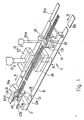
- a method of making connections for electric wires in a junction device comprising a group of electrical insulation wires aligned in a parallel or an almost parallel longitudial direction and including a junction for making electrical contact means having at least one supporting frame of electrical insulating material and connection tabs whose each of the one end portions forms U-shaped wire slot with an insulation penetrating blades and the other end of each tabs is formed a male connection terminal to be mated with corresponding female portion in a connector housing, an electrical connector attached to one end portions of the group of electric wires, a holding means for the connector, wire clamping means for clamping the other end portions of the group of electric wires, a depression connectign mechanism consisting of a junction platform and a mating depression mold between two wire-clamping means, tensioning means for providing londitudinal stretch to the wires placed between the wire clamping means and the connector holding means.
- a group of electric wires are connected with depression to the U-shaped slot portions of the connection tabs which have been attached to the substrate having through holes for passing the connection tabs, and which have been placed on a the wire pathes.
- the free end portion of the group of wires which is opposite to the one with an electrical connector can be terminated in a range beginning at the corner end portion of the wire junction device after connections between wires and connection tabs have been made.
- the wires should be terminated without surplus length beyond its edge portions.
- a further feature of the present invention provides good longitudinal alignment of the electric wires during the process of making connections with connection tabs at their U-shaped slots and the good alignment of the wires offers reliable connection therebetween.
- the method of the present invention includes substantially the following four steps.
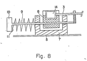
- the carrier belts are driven in a synchronous movement to direction X keeping both the clamping mechanism and the wire junction means out of application to the wires (3) until the connector (14) in the holder (8) reaches point H which is located near to the wire junction means (2).
- the wire clamping mechanism now works in such manner that the connector holder (8) can proceed against the friction caused by the pinching roller (16) and the insulation layer of the electric wires (3) keeping them in an parallel alignment by means of two comb-shaped wire dispensers (12)(13).
- the wire junction means are applied.
- An example of making junction to the wires is shown through Fig.2 to Fig.5.
- a wire junction device (2) usually has a multi-layered structure in which several groups of wires are connected independently to the U-shaped slots of connection tabs within a layer.
- FIG.4 and Fig.5. an overside perspective views of mono-layered junction device are shown in Fig.4 and Fig.5.
- Fig.4 projections and recesses are formed side by side within a line of wire supporting structure on the top surface of the junction device (2).
- a group of recesses are aligned to form a common straight line in which electrical wires to be connected is placed in the longitudinal direction X.
- connection tabs (1) are aligned in pitches corresponding to those of electrical terminal of an mating electrical connector or connectors to which wires are to be connected through connection tabs (1).
- connection tab (1) In the grooves (19) between the above described wire holding structure there are U-shaped slots (1a) of connection tab (1) projecting vertically through the bottom of the frame (2a) of the junction device (2) with their blades on the wire passway.
- Each of the group of electric wires (3) can be fitted with the blade portion of the U-shaped slot (1a) as illustrated in Fig.5.
- the junction platform (18) ascends in such a way that the wires (3) to be connected will come into an mating engagement with each of the bladed U-shaped slot (1a) of the connection tabs (1) which are standing upright out of the frame (2a) of the junction device (2).
- the depression molder (4) now descends and its wire depressing projection (4b) depresses the mating wire portions downward until the descending movement is terminated by the holding blocks (6) located on the top surface of the bottom plate (18).
- the wires (3) are always stretched in X direction due to the compression spring (11) and they are frictionally supported by the pinching roller (16). They are, therefore, forcedly pulled inwardly during the junction operation eliminating wire damages due to an excessive stretch and also preventing wire from disalignment caused by an excess release of them.
- the electric wires are in an excellent parallel longitudinal alignment and reliable connections between wires and connection tabs in its U-shaped slots are achieved as the wires are frictionally maintained at their one end portions and continuously stretched at their another end portions with spring and further inwardly pulled against the above forces without an excessive downward depression during connecting operation by the junction means.
Landscapes
- Engineering & Computer Science (AREA)
- Manufacturing & Machinery (AREA)
- Manufacturing Of Electrical Connectors (AREA)
- Multi-Conductor Connections (AREA)
Applications Claiming Priority (2)
| Application Number | Priority Date | Filing Date | Title |
|---|---|---|---|
| JP131872/87 | 1987-08-28 | ||
| JP1987131872U JPH0429518Y2 (de) | 1987-08-28 | 1987-08-28 |
Publications (3)
| Publication Number | Publication Date |
|---|---|
| EP0304875A2 true EP0304875A2 (de) | 1989-03-01 |
| EP0304875A3 EP0304875A3 (en) | 1990-11-07 |
| EP0304875B1 EP0304875B1 (de) | 1993-03-17 |
Family
ID=15068110
Family Applications (1)
| Application Number | Title | Priority Date | Filing Date |
|---|---|---|---|
| EP88113718A Expired - Lifetime EP0304875B1 (de) | 1987-08-28 | 1988-08-23 | Verfahren zum Verbinden von elektrischen Leitern in einer Verbindungsvorrichtung und Vorrichtung zur Ausführung des Verfahrens |
Country Status (8)
| Country | Link |
|---|---|
| US (1) | US4908941A (de) |
| EP (1) | EP0304875B1 (de) |
| JP (1) | JPH0429518Y2 (de) |
| KR (1) | KR910003915Y1 (de) |
| CN (1) | CN2056546U (de) |
| CA (1) | CA1303337C (de) |
| DE (1) | DE3879324D1 (de) |
| MY (1) | MY103384A (de) |
Families Citing this family (14)
| Publication number | Priority date | Publication date | Assignee | Title |
|---|---|---|---|---|
| US5074038A (en) * | 1991-01-25 | 1991-12-24 | Amp Incorporated | Cable making machine and method of manufacture |
| JPH08162177A (ja) * | 1994-12-05 | 1996-06-21 | Yazaki Corp | 圧接コネクタへの電線圧接方法及び圧接コネクタ |
| JPH09161548A (ja) * | 1995-12-05 | 1997-06-20 | Harness Sogo Gijutsu Kenkyusho:Kk | ワイヤーハーネス用フラット電線及びその製造 |
| JPH10203271A (ja) * | 1997-01-28 | 1998-08-04 | Harness Sogo Gijutsu Kenkyusho:Kk | 自動車用ワイヤーハーネスの製造 |
| JP3889846B2 (ja) * | 1997-03-19 | 2007-03-07 | 矢崎総業株式会社 | 圧接布線装置及びハーネス製造方法 |
| JP2004288546A (ja) * | 2003-03-24 | 2004-10-14 | Auto Network Gijutsu Kenkyusho:Kk | 電線圧接装置 |
| JP5644697B2 (ja) * | 2011-06-24 | 2014-12-24 | 住友電装株式会社 | ワイヤーハーネスの製造方法、電線支持装置及び連結型電線保持バー |
| JP5950305B2 (ja) * | 2012-09-26 | 2016-07-13 | 矢崎総業株式会社 | 電線圧接装置 |
| CN103490265B (zh) * | 2013-09-24 | 2015-08-19 | 国网上海市电力公司 | 一种防松股的导线压接方法 |
| KR102100340B1 (ko) * | 2015-03-31 | 2020-04-13 | 캐논 가부시끼가이샤 | 촬상 장치의 장치본체 |
| CN107248681B (zh) * | 2017-06-01 | 2019-05-31 | 芜湖侨云友星电气工业有限公司 | 一种线束压线装置 |
| CN107302197B (zh) * | 2017-06-20 | 2018-11-09 | 荆门市格林美新材料有限公司 | 一种细旧电缆剥皮回收装置 |
| CN107887772B (zh) * | 2017-11-28 | 2024-02-06 | 海盐县盛安电器有限公司 | 一种电线端子铆接装置 |
| CN114824983B (zh) * | 2022-04-15 | 2024-03-26 | 芜湖侨云友星电气工业有限公司 | 一种新能源汽车高压线束总成的自动化制造装置 |
Family Cites Families (14)
| Publication number | Priority date | Publication date | Assignee | Title |
|---|---|---|---|---|
| GB1076628A (en) * | 1965-08-19 | 1967-07-19 | Nat Res Dev | Connectors for use on tape cables |
| US4110880A (en) * | 1977-02-25 | 1978-09-05 | Amp Incorporated | Cable harness assembly and electrical testing machine |
| US4126935A (en) * | 1977-05-31 | 1978-11-28 | Bell Telephone Laboratories, Incorporated | Method and apparatus for manufacturing wiring harnesses |
| US4103417A (en) * | 1977-08-25 | 1978-08-01 | Dataproducts (Santa Clara), Inc. | Wire stringing device |
| US4148130A (en) * | 1977-12-06 | 1979-04-10 | Amp Incorporated | Cable harness assembly apparatus |
| US4235015A (en) * | 1979-02-16 | 1980-11-25 | Molex Incorporated | Electrical harness fabrication method and apparatus |
| DE2928704A1 (de) * | 1979-07-16 | 1981-02-19 | Amp Inc | Vorrichtung zum gleichzeitigen anschluss einer reihe von kabeln an entsprechende kontakte |
| US4419817A (en) * | 1981-10-13 | 1983-12-13 | Molex Incorporated | Electrical harness fabrication apparatus |
| US4646404A (en) * | 1983-07-07 | 1987-03-03 | Nippon Acchakutanshi Seizo Kabushiki Kaisha | Apparatus for manufacturing electrical harnesses |
| JPS60117583A (ja) * | 1983-11-29 | 1985-06-25 | 日本圧着端子製造株式会社 | 自動圧接機における電線長さバリエ−シヨン装置 |
| EP0171737B1 (de) * | 1984-08-07 | 1990-12-27 | Sumitomo Wiring Systems, Ltd. | Steckverbindervorrichtung zum Anschliessen von elektrischen Kabeln |
| DD226701A1 (de) * | 1984-09-03 | 1985-08-28 | Kontaktbau & Spezmaschbau Veb | Vorrichtung zum anschliessen isolierter draehte an einem leitungsverbinder |
| JPS6171575A (ja) * | 1984-09-13 | 1986-04-12 | 日本圧着端子製造株式会社 | 片端自動圧接機 |
| US4682391A (en) * | 1985-08-21 | 1987-07-28 | Amp Incorporated | Cable harness assembly apparatus |
-
1987
- 1987-08-28 JP JP1987131872U patent/JPH0429518Y2/ja not_active Expired
-
1988
- 1988-08-23 DE DE8888113718T patent/DE3879324D1/de not_active Expired - Lifetime
- 1988-08-23 EP EP88113718A patent/EP0304875B1/de not_active Expired - Lifetime
- 1988-08-26 CA CA000575766A patent/CA1303337C/en not_active Expired - Fee Related
- 1988-08-26 US US07/237,507 patent/US4908941A/en not_active Expired - Fee Related
- 1988-08-26 CN CN88214156U patent/CN2056546U/zh not_active Expired - Lifetime
- 1988-08-26 MY MYPI88000962A patent/MY103384A/en unknown
- 1988-08-27 KR KR2019880013988U patent/KR910003915Y1/ko not_active Expired
Also Published As
| Publication number | Publication date |
|---|---|
| EP0304875A3 (en) | 1990-11-07 |
| JPH0429518Y2 (de) | 1992-07-16 |
| KR910003915Y1 (ko) | 1991-06-07 |
| CA1303337C (en) | 1992-06-16 |
| EP0304875B1 (de) | 1993-03-17 |
| KR890005728U (ko) | 1989-04-21 |
| MY103384A (en) | 1993-06-30 |
| JPS6436993U (de) | 1989-03-06 |
| CN2056546U (zh) | 1990-04-25 |
| DE3879324D1 (de) | 1993-04-22 |
| US4908941A (en) | 1990-03-20 |
Similar Documents
| Publication | Publication Date | Title |
|---|---|---|
| EP0304875B1 (de) | Verfahren zum Verbinden von elektrischen Leitern in einer Verbindungsvorrichtung und Vorrichtung zur Ausführung des Verfahrens | |
| CA1086030A (en) | Method of, and apparatus for, manufacturing electrical harnesses | |
| US6105229A (en) | Apparatus for securing twisted-pair electrical cable to a connector | |
| US3611264A (en) | Wire connecting blocks | |
| EP0034000B1 (de) | Anschlussklemme für Schaltplatten | |
| US4026629A (en) | Method of manufacturing an electrical harness and electrical connectors and terminals for carrying out the method | |
| CA1085013A (en) | Electrical conductor terminating system | |
| JPH01186578A (ja) | クランプ装置及び導線挿入装置 | |
| EP0311149B1 (de) | Maschine für die Herstellung eines elektrischen Kabelbaumes | |
| US4789354A (en) | Voice/data communication termination connector | |
| US4508410A (en) | Electrical termination system and connector member | |
| CA1055233A (en) | Assembly tooling for electrical connectors | |
| US4178055A (en) | Connecting device for connecting pairs of wires | |
| US4797112A (en) | Wire holders and harnesses incorporating wire holders | |
| US5547391A (en) | Commoning electrical connector | |
| EP0789939B1 (de) | Elektrischer Steckverbinder | |
| US4831726A (en) | Wiring harness and method for manufacturing same | |
| US5370558A (en) | Wire retainer | |
| US3988815A (en) | Apparatus for terminating a cable | |
| US4342152A (en) | Methods of terminating and connectorizing cables | |
| US4282644A (en) | Tool for assembling conductors to connector element | |
| US4232444A (en) | Flat cable stripping and terminating technique | |
| US4295254A (en) | Transmission line cable applicator machine | |
| US4060890A (en) | Method of manufacturing an electrical harness | |
| US4570326A (en) | Cable harness assembly apparatus |
Legal Events
| Date | Code | Title | Description |
|---|---|---|---|
| PUAI | Public reference made under article 153(3) epc to a published international application that has entered the european phase |
Free format text: ORIGINAL CODE: 0009012 |
|
| AK | Designated contracting states |
Kind code of ref document: A2 Designated state(s): DE FR GB |
|
| PUAL | Search report despatched |
Free format text: ORIGINAL CODE: 0009013 |
|
| AK | Designated contracting states |
Kind code of ref document: A3 Designated state(s): DE FR GB |
|
| 17P | Request for examination filed |
Effective date: 19901030 |
|
| 17Q | First examination report despatched |
Effective date: 19911209 |
|
| RTI1 | Title (correction) | ||
| GRAA | (expected) grant |
Free format text: ORIGINAL CODE: 0009210 |
|
| AK | Designated contracting states |
Kind code of ref document: B1 Designated state(s): DE FR GB |
|
| PG25 | Lapsed in a contracting state [announced via postgrant information from national office to epo] |
Ref country code: FR Effective date: 19930317 Ref country code: DE Effective date: 19930317 |
|
| REF | Corresponds to: |
Ref document number: 3879324 Country of ref document: DE Date of ref document: 19930422 |
|
| EN | Fr: translation not filed | ||
| PLBE | No opposition filed within time limit |
Free format text: ORIGINAL CODE: 0009261 |
|
| STAA | Information on the status of an ep patent application or granted ep patent |
Free format text: STATUS: NO OPPOSITION FILED WITHIN TIME LIMIT |
|
| 26N | No opposition filed | ||
| PGFP | Annual fee paid to national office [announced via postgrant information from national office to epo] |
Ref country code: GB Payment date: 20000823 Year of fee payment: 13 |
|
| PG25 | Lapsed in a contracting state [announced via postgrant information from national office to epo] |
Ref country code: GB Free format text: LAPSE BECAUSE OF NON-PAYMENT OF DUE FEES Effective date: 20010823 |
|
| GBPC | Gb: european patent ceased through non-payment of renewal fee |
Effective date: 20010823 |