EP0304844B1 - Verfahren zum Herstellen von Floatglas - Google Patents
Verfahren zum Herstellen von Floatglas Download PDFInfo
- Publication number
- EP0304844B1 EP0304844B1 EP88113620A EP88113620A EP0304844B1 EP 0304844 B1 EP0304844 B1 EP 0304844B1 EP 88113620 A EP88113620 A EP 88113620A EP 88113620 A EP88113620 A EP 88113620A EP 0304844 B1 EP0304844 B1 EP 0304844B1
- Authority
- EP
- European Patent Office
- Prior art keywords
- molten metal
- bath
- glass ribbon
- magnetic field
- metal bath
- Prior art date
- Legal status (The legal status is an assumption and is not a legal conclusion. Google has not performed a legal analysis and makes no representation as to the accuracy of the status listed.)
- Expired - Lifetime
Links
Images


Classifications
-
- C—CHEMISTRY; METALLURGY
- C03—GLASS; MINERAL OR SLAG WOOL
- C03B—MANUFACTURE, SHAPING, OR SUPPLEMENTARY PROCESSES
- C03B18/00—Shaping glass in contact with the surface of a liquid
- C03B18/02—Forming sheets
- C03B18/18—Controlling or regulating the temperature of the float bath; Composition or purification of the float bath
Definitions
- the present invention relates to a method for manufacturing float glass.
- a molten metal bath used for the method of manufacturing float glass is divided generally into three regions along the direction of movement of a glass ribbon.
- a first region is called a fire polishing region which is adapted to receive molten glass on the surface of the molten metal bath in which a glass ribbon having an equilibrium thickness is formed while the width of the glass ribbon is expanded and at the same time the surface of the ribbon is made flat.
- soda-lime glass is used for the molten glass and it is kept at a temperature of 1,110°C-950°C.
- a second region is used for forming the glass ribbon in a predetermined thickness.
- the second region is especially so constructed that, when glass having a thickness lower than an equilibrium thickness is to be formed, a pulling force is applied to the glass ribbon in its longitudinal direction while top rollers are engaged with both edges of the glass ribbon to suppress contraction of the glass ribbon in its width direction to thereby form the glass ribbon having a predetermined thickness.
- the top rollers are placed to be engageable with the glass ribbon.
- the second region is kept at a temperature sufficient to change the thickness of the glass ribbon when it is pulled by a pulling force. Namely, the glass ribbon is formed at a temperature range of about 950°C-800°C when soda-lime glass is used.
- a third region is so adapted that the glass ribbon formed in a predetermined thickness can be drawn from the molten metal bath and the glass ribbon is cooled to a temperature suitable to be transferred by means of rollers.
- the third region is kept at a temperature ranging from about 800°C-600°C when soda-lime glass is used.
- a temperature distribution in the molten metal bath in its longitudinal direction has been attained by changing the depth of the metal bath as shown in Japanese Examined Patent Publication No. 18353/1966, or by arranging a barrier at the boundary of each region.
- the upper end of the barrier it is necessary to determine the upper end of the barrier to be 20 mm-30 mm lower than the bath surface of the molten metal in order to avoid the contact between the barrier and the glass ribbon.
- the depth of the metal bath is so determined that the thinnest glass ribbon can be produced. Accordingly, when a glass ribbon having a relatively large thickness is manufactured, there is a useless glass ribbon forming region, which results in increases of heat loss.
- a moveable barrier system is proposed.
- a movable barrier can not be used for a vessel in which the cross-sectional area in its width direction is not uniform.
- a direct current magnetic field (hereinbelow, referred to as a d.c. magnetic field) used in the present invention is a magnetic field excited by a direct current without pulsation or a full-wave-rectified d.c. current, or produced by using a permanent magnet.
- the method of the present invention utilizes a Lorentz force which is used for controlling the movement of the molten metal bath by applying the d.c. magnetic field to the molten metal bath when it moves in the direction transversing a magnetic flux. Namely, the movement of the molten metal bath, caused by a gradient of temperature, by the movement of glass ribbon and by other causes, is suppressed by the d.c. magnetic field.
- the magnitude of the d.c. magnetic field required for controlling the movement of the molten metal bath becomes large as the depth of the molten metal bath increases, and the gradient of temperature in the metal bath is larger. For instance, when the depth of the bath is 40 mm, and the gradient of temperature in the bath is 100°C/m, some effect is obtained at about 0.03 Tesla, and the movement of the molten metal bath can be substantially suppressed at 0.4 Tesla-0.6 Tesla.
- a permanent magnet As the means of applying the d.c. magnetic field, a permanent magnet, a d.c. electromagnet and so on may be used.
- the d.c. electromagnet is most desirable because the strength of the magnetic field can be easily adjusted.
- such means is arranged at the upper part or the lower part of the molten metal bath.
- the d.c. magnetic field producing means may be provided at both the upper and lower parts of the molten metal bath. At least one superconductive coil may be used to provide a further large d.c. magnetic field, instead of the electromagnet.
- reference numeral 1 designates a molten metal bath
- numeral 3 designates a glass ribbon
- numerals 4, 10, 11 designate d.c. magnets.
- the d.c. magnet 4 is disposed in an upper space in a vessel 2 holding the molten metal bath 1 at a position near the glass ribbon so as to suppress the movement of the molten metal bath.
- the position of the d.c. electromagnet 4 adjoins an area where the glass ribbon is formed substantially in a predetermined thickness.
- the d.c. electromagnet 4 comprises an iron core 5, a plurality of windings 6 wound around the iron core and a heat insulating material such as a castable covering the outer circumferenece of the iron core and windings.
- the windings 6 are cooled by feeding water into a pipe made of copper to prevent the windings from overheating (although the pipe is not shown in the Figures).
- Numerals 8 and 9 designate cooling devices for cooling the glass ribbon.
- the d.c. electromagnet 10 is separately provided below the vessel 2 so as to oppose the d.c. electromagnet 4 in the vessel 1.
- the d.c. electromagnet 10 also comprises an iron core 5, a plurality of windings 6 to be cooled by water and a heat insulating material 7 covering the outer circumference of the iron core and the windings in the same manner as the electromagnet 4.
- the d.c. electromagnet 11 is disposed near the outlet of the vessel 1 to suppress the movement of the molten metal at or near the outlet.
- the d.c. electromagnet 11 also has the same construction as the elctromagnets 4, 10.
- a linear induction motor 12 is disposed below the vessel 1 so that a travelling magnetic field (which travels toward the downstream side of the vessel) is applied to the molten metal bath, whereby an electric current is induced in the molten metal bath.
- the resulted electric current receives a Lorentz force by the travelling mganetic field.
- a body force is produced in the molten metal bath in the same direction as the travelling magnetic field, whereby the level of a first horizontal bath surface formed at the upstream side in the vessel is lower than a second horizontal bath surface at the downstream side as shown in Figure 1.
- a purified molten glass is continuously supplied on the first horizontal surface of the molten metal bath.
- the supplied molten glass spreads on the bath surface to form a glass ribbon 3 having a substantially equilibrium thickness and the surface of the glass ribbon 3 is fire-polished.
- the viscosity ⁇ (in poise) of the glass in the above-mentioned region is in a range of 3.1-4.8 in common logarithm.
- the glass ribbon 3 is moved forward from the first bath surface to the second bath surface while it is stretched by a pulling force of a lehr to have a predetermined thickness.
- a difference in height formed between the first and second bath surfaces is large as the predetermined thickness of glass ribbon i.e. the thickness of a glass product is small.
- the height difference i.e. the thickness of a glass product is small.
- the height difference of about 2.8 mm is produced by applying a travelling magnetic field of 5 x 10 ⁇ 3 Tesla in the region having a length of 1 m in the directiosn of moving the glass ribbon.
- Glass ribbon width maintaining members 13 are provided in the inner side surfaces of the vessel 1 in order to prevent the glass ribbon 3 from contracting in its width direction as shown in Figure 2.
- the maintaining members 13 are made of a material difficult to wet a molten metal and glass, such material being made of, for instance, graphite or BN.
- Each of the maintaining members 13 is so formed that the upper surface is inclined inwardly and downwardly so that the bath surface of the molten metal in the vessel 1 forms a meniscus and both edges of the bath surface are in contact with the inclined surfaces as shown in Figure 2.
- the glass ribbon takes a configuration in which both edges are along the shape of the glass surface of the molten metal bath, whereby contraction in the width of the glass ribbon is prevented. It is preferable that the maintaining members 13 extend to positions where the thickness of the glass ribbon is not substantially changed, i.e. the viscosity of the glass ribbon is about 6.5 (log ⁇ ).
- the glass ribbon is moved forward on the bath surface of the molten metal bath to which a d.c. magnetic field is applied by the d.c. electromagnets 4, 10 to substantially suppress the movement of the molten metal, and the ribbon is rapidly cooled to have a viscosity (long ⁇ ) of about 6.5 by the cooling devices 8, 9. Since there is no substantial movement in the molten metal bath in this region, the functions of conduction and radiation substantially contribute to the transfer of heat in the vessel. Accordingly, there is no local change in temperature even when the glass ribbon is rapidly cooled, and distortion does not take place in the glass ribbon. Further, a large gradient of temperature can be provided in the vessel in the direction of moving the glass ribbon. In this case, the strength of the d.c.
- a reference numeral 14 designate an electric conducting material made of tungsten, which prevents a body force by the linear induction motor 12 from reducing in the vicinity of the side walls of the vessel.
- the glass ribbon 3 is moved forward while being cooled, and it reaches an area on the bath surface where a d.c. electromagnet 11 is disposed.
- the molten metal bath in this area is subjected to control of its movement by the electromagnet 11.
- the strength of the magnetic field formed by the d.c. electromagnet 11 is in a range of about 0.03 Tesla-0.1 Tesla.
- the glass ribbon is moved forwardly on the bath surface until the glass ribbon has a viscosity (log ⁇ ) of 6.5-14.5 during which the glass ribbon is gradually cooled.
- a reference numeral 15 designates a linear induction motor which provides a body force to urge the molten metal bath to the upstream side, whereby it prevents the molten metal from overflowing at the outlet of the vessel which is lower than the bath surface. Accordingly, the cooled glass ribbon is pulled horizontally from the bath surface without contacting the vessel.
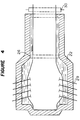
- Figures 3 and 4 shows another embodiment of the apparatus used for carrying out the method of manufacturing float glass of the present invention.
- a reference numeral 21 designates a molten metal bath and numerals 23, 27 designate d.c. electromagnets.
- a d.c. electromagnet 23 is disposed below a vessel 22 which holds the molten metal bath 21.
- the electromagnet 23 comprises an iron core and a plurality of windings 25 so that a d.c. magnetic field of about 0.03 Tesla-0.1 Tesla can be applied to the molten metal bath.
- a barrier 26 is arranged in the vessel 22 at the downstream side of the electromagnet 23. The upper edge of the barrier 26 is determined to be lower than the bath surface of the molten metal bath by about 25 mm.
- a second d.c. electromagnet 27 is disposed above the barrier 26 in the vessel 22, and a cooling device 28 is provided at the lower surface of the second d.c. electromagnet 27.
- the electromagnet 27 comprises an iron core and a plurality of windings in the same manner as the electromagnet 23 so that a magnetic field of about 0.1 Tesla-0.6 Tesla can be applied to the molten metal bath.
- a purified molten glass is continuously supplied onto the molten metal bath to form a glass ribbon.
- the glass ribbon is engaged with a plurality of top rollers 29 which are provided near both inner sides of the vessel 22 and cooled by water so that the glass ribbon is moved forward while it receives forces in both the directions of upstream and width, whereby it is formed in a predetermined thickness.
- the molten metal bath flows from the upstream side to the downstream side at its surface area, and it flows from the downstream side to the upstream side in the vicinity of the top end of the barrier.
- a magnetic flux as indicated by arrow marks, by the d.c. electromagnet 27.
- the d.c. electromagnet to form a d.c. magnetic field may be replaced by a parmanent magnet.
- the present invention is applicable to the manufacture of float glass having an equilibrium thickness or a greater thickness although description has been made as to the manufacture of float glass having less than an equibilium thickness.
- a desired function can be obtained by changing polarity applied to the linear induction motor 12 to form a travelling magnetic field moving the uppersteam side so that the bath surface of the first horizontal molten metal bath is higher than that of the second horizontal metal bath.
- a kinematic viscosity ⁇ e equivalent to a magnetic field is represented by: wheres ⁇ is electric conductivity of molten metal, H is a depth of a bath of thin, B is the density of a magnetic flux and ⁇ , is the density of molten metal.
- a magnetic field can suppress a stream of a molten metal flowing perpendicular to the direction of a magnetic field.
- a convection is dominantly produced in the direction, perpendicular to the direction of gravity, i.e. in the horizontal direction of the bath.
- an effective direction of magnetic field has a vertical component.
- the function to suppress the convection in the bath is not only a magnetic field in the vertical direction, but also the horizontal component in the magnetic field.
- a molten tin bath having a depth of 25 mm was prepared.
- a temperature difference of 100°C per 1 m was formed in the molten thin bath between the high temperature side and the low temperature side.
- a magnetic field was formed in the bath by a d.c. electromagnet having a coil pitch of about 75 mm.
- a magnetic field of about 0.03 Tesla was applied to the bath, the temperature variation of about 6°C at the maximum was reduced to 0.2°C or lower. In this case, heat-interruption effect for the molten thin bath was about 40%.
- a magnetic field of about 0.1 Tesla was formed in the same bath. A temperature change could not substantially be measured. Heat-interruption effect for the molten tin was about 90%, or higher. In this state, substantially the entire heat conducting state is obtainable.
- the heat-interruption effect was measured by an amount of reducing power for heating the molten tin by an electric heater at the high temperature side.
- the movement of the molten metal bath can be suppressed, whereby distortion generated in a glass ribbon due to partial change in temperature can be greatly reduced. Further, since heat conduction which results from the movement of the bath can be reduced, a large gradient of temperature can be formed in the direction of forwarding the glass ribbon. This minimizes the size of vessel, and accordingly, the apparatus can be small-sized as a whole, and heat loss in the bath can be minimized.
- a glass ribbon having a predetermined thickness can be formed by providing a level difference between a first horizontal bath surface at the upstream side in the vessel and a second horinzontal bath surface at the downstream side by using a linear induction motor.
- a linear induction motor it is unnecessary to use top rollers, and accordingly, both edge portions of the glass ribbon can be used as glass products, whereby working efficiency can be increased.
Landscapes
- Chemical & Material Sciences (AREA)
- Engineering & Computer Science (AREA)
- Materials Engineering (AREA)
- Organic Chemistry (AREA)
- Continuous Casting (AREA)
Claims (4)
- Verfahren zum Herstellen von Floatglas durch kontinuierliches Zuführen geschmolzenen Glases auf die Oberfläche eines Bades (1) aus geschmolzenem Metall, um ein Glasband herzustellen, Vorwärtsbewegen des Glasbandes entlang der Badoberfläche, so, daß sich eine vorgegebene Dicke einstellt, und Abkühlen des Glasbandes mit der vorgegebenen Dicke durch Vorwärtsbewegen desselben auf der Oberfläche des Bades aus geschmolzenem Metall, dadurch gekennzeichnet, daß mindestens ein Gleichmagnetfeld dort an das Bad (1) aus geschmolzenem Metall angelegt wird, wo es Konvektionsströmungen im Bad (1) aus gesohmolzenem Metall im wesentlichen unterdrückt.
- Verfahren zum Herstellen von Floatglas gemäß Anspruch 1, bei dem die Stärke des Gleichmagnetfelds im Bereich von 0,03 Tesla bis 0,6 Tesla liegt.
- Verfahren zum Herstellen von Floatglas nach Anspruch 1, bei dem das Gleichmagnetfeld von mindestens einem Gleichstrom-Elektromagneten (10) erzeugt wird.
- Verfahren zum Herstellen von Floatglas nach Anspruch 1, bei dem das Gleichmagnetfeld an die stromabwärtige Seite des Bads (1) aus geschmolzenem Metall angelegt wird.
Applications Claiming Priority (2)
| Application Number | Priority Date | Filing Date | Title |
|---|---|---|---|
| JP208354/87 | 1987-08-24 | ||
| JP62208354A JPH07108779B2 (ja) | 1987-08-24 | 1987-08-24 | フロ−トガラスの製造法 |
Publications (3)
| Publication Number | Publication Date |
|---|---|
| EP0304844A2 EP0304844A2 (de) | 1989-03-01 |
| EP0304844A3 EP0304844A3 (en) | 1990-08-29 |
| EP0304844B1 true EP0304844B1 (de) | 1994-08-03 |
Family
ID=16554898
Family Applications (1)
| Application Number | Title | Priority Date | Filing Date |
|---|---|---|---|
| EP88113620A Expired - Lifetime EP0304844B1 (de) | 1987-08-24 | 1988-08-22 | Verfahren zum Herstellen von Floatglas |
Country Status (5)
| Country | Link |
|---|---|
| US (1) | US4940479A (de) |
| EP (1) | EP0304844B1 (de) |
| JP (1) | JPH07108779B2 (de) |
| CA (1) | CA1323984C (de) |
| DE (1) | DE3850921T2 (de) |
Cited By (1)
| Publication number | Priority date | Publication date | Assignee | Title |
|---|---|---|---|---|
| CN110072820A (zh) * | 2016-12-23 | 2019-07-30 | 法国圣戈班玻璃厂 | 改进的通过浮法制备平板玻璃的方法 |
Families Citing this family (12)
| Publication number | Priority date | Publication date | Assignee | Title |
|---|---|---|---|---|
| US5948133A (en) * | 1996-02-29 | 1999-09-07 | Asahi Glass Company Ltd. | Method for holding an edge of a molten glass flow |
| US6003337A (en) * | 1996-12-26 | 1999-12-21 | Asahi Glass Company Ltd. | Method and apparatus for producing a sheet glass |
| US7318330B2 (en) * | 2003-06-27 | 2008-01-15 | Schott Corporation | Mobile device and a process for the production of glass |
| WO2006029695A1 (de) * | 2004-09-18 | 2006-03-23 | Schott Ag | Verfahren und vorrichtung zur herstellung von flachglas nach dem floatverfahren |
| DE102007014806A1 (de) | 2007-03-28 | 2008-10-02 | Schott Ag | Verfahren und Vorrichtung zur Bewegung einer freien Metalloberfläche geschmolzenen Metalls |
| KR20100062602A (ko) * | 2008-12-02 | 2010-06-10 | 삼성전자주식회사 | 유리 기판, 그를 포함하는 표시 장치 및 표시 장치의 제조 방법 |
| KR101561973B1 (ko) * | 2009-02-13 | 2015-10-21 | 주식회사 엘지화학 | 유리판 제조 장치 |
| KR101563682B1 (ko) * | 2009-02-13 | 2015-10-28 | 주식회사 엘지화학 | 유리판 제조 장치 |
| CN103030261B (zh) * | 2011-09-30 | 2015-05-13 | 信义电子玻璃(芜湖)有限公司 | 装有锡液的锡槽 |
| JP6626491B2 (ja) * | 2014-07-10 | 2019-12-25 | コーニング インコーポレイテッド | ガラス製造装置および方法 |
| US20160122224A1 (en) * | 2014-11-03 | 2016-05-05 | Ppg Industries Ohio, Inc. | Automated float glass system |
| FR3066191B1 (fr) * | 2017-05-12 | 2022-10-21 | Saint Gobain | Procede ameliore de fabrication de verre plat par flottage |
Family Cites Families (10)
| Publication number | Priority date | Publication date | Assignee | Title |
|---|---|---|---|---|
| US3860406A (en) * | 1967-10-11 | 1975-01-14 | Ford Motor Co | Method of manufacturing glass |
| GB1242330A (en) * | 1969-06-16 | 1971-08-11 | Saratovsky Gnii Stekla | Improvements in and relating to the manufacture of sheet glass |
| GB1245328A (en) * | 1969-12-15 | 1971-09-08 | Saratovsky Gni Vatelskogo I St | Bath for use in installation for producing sheet glass |
| GB1316754A (en) * | 1970-03-09 | 1973-05-16 | Pilkington Brothers Ltd | Lawrenson j manufacture of flat glass |
| GB1315365A (en) * | 1970-06-04 | 1973-05-02 | Pilkington Brothers Ltd | Manufacture of float glass |
| GB1354537A (en) * | 1971-07-09 | 1974-06-05 | Pilkington Brothers Ltd | Manufacture of flat glass |
| GB1509917A (en) * | 1974-08-28 | 1978-05-04 | Glaverbel | Production or treatment of flat glass |
| SU548188A1 (ru) * | 1975-09-19 | 1982-09-07 | Саратовский Филиал Государственного Научно-Исследовательского Института Стекла | Способ изготовлени листового стекла из стекломассы |
| JPS6016824A (ja) * | 1983-07-07 | 1985-01-28 | Asahi Glass Co Ltd | フロ−トガラスの製造法 |
| US4784680A (en) * | 1986-07-03 | 1988-11-15 | Asahi Glass Company Ltd. | Method of and apparatus for manufacturing float glass |
-
1987
- 1987-08-24 JP JP62208354A patent/JPH07108779B2/ja not_active Expired - Fee Related
-
1988
- 1988-08-17 CA CA000574997A patent/CA1323984C/en not_active Expired - Fee Related
- 1988-08-22 US US07/234,677 patent/US4940479A/en not_active Expired - Fee Related
- 1988-08-22 EP EP88113620A patent/EP0304844B1/de not_active Expired - Lifetime
- 1988-08-22 DE DE3850921T patent/DE3850921T2/de not_active Expired - Fee Related
Cited By (2)
| Publication number | Priority date | Publication date | Assignee | Title |
|---|---|---|---|---|
| CN110072820A (zh) * | 2016-12-23 | 2019-07-30 | 法国圣戈班玻璃厂 | 改进的通过浮法制备平板玻璃的方法 |
| CN110072820B (zh) * | 2016-12-23 | 2022-06-24 | 法国圣戈班玻璃厂 | 改进的通过浮法制备平板玻璃的方法 |
Also Published As
| Publication number | Publication date |
|---|---|
| DE3850921D1 (de) | 1994-09-08 |
| JPS6452625A (en) | 1989-02-28 |
| EP0304844A2 (de) | 1989-03-01 |
| EP0304844A3 (en) | 1990-08-29 |
| DE3850921T2 (de) | 1995-02-16 |
| CA1323984C (en) | 1993-11-09 |
| US4940479A (en) | 1990-07-10 |
| JPH07108779B2 (ja) | 1995-11-22 |
Similar Documents
| Publication | Publication Date | Title |
|---|---|---|
| EP0304844A2 (de) | Verfahren zum Herstellen von Floatglas | |
| RU2236770C2 (ru) | Устройство индукционного нагрева с поперечным потоком и магнитной цепью изменяемой ширины | |
| US3985179A (en) | Electromagnetic casting apparatus | |
| US4101304A (en) | Method and apparatus for feeding glass out of a melting tank to a flat glass forming means | |
| TWI627140B (zh) | 以感應加熱之方式於邊緣導引件上最小化失透性之方法及設備 | |
| US20080223079A1 (en) | Apparatus and process for producing a float glass | |
| US4784680A (en) | Method of and apparatus for manufacturing float glass | |
| EP0131230B1 (de) | Verfahren zur Herstellung von Flachglas | |
| US3492107A (en) | Method and apparatus for producing float glass utilizing electrically resistive refractory confining walls | |
| US4325777A (en) | Method and apparatus for reforming an improved strip of material from a starter strip of material | |
| US4361431A (en) | Method of forming thin sheet glass by float process | |
| US3533773A (en) | Apparatus for manufacturing float glass with graphite heating means | |
| US3630703A (en) | Float glass method and apparatus for supplying modifying material to the glass surface | |
| US3647408A (en) | Method and apparatus for manufacture of float glass | |
| CN116669246B (zh) | 一种电磁加热装置及其控制方法 | |
| JP2001006861A (ja) | 電磁誘導加熱装置 | |
| US3770406A (en) | Manufacture of wired glass on molten metal bath | |
| CN100577585C (zh) | 浮法平板玻璃的制造方法及其装置 | |
| ES348769A1 (es) | Un procedimiento de formar una cinta de vidrio plano. | |
| KR20120087524A (ko) | 침지노즐 막힘 방지 장치 | |
| TW201841841A (zh) | 用於在玻璃製造處理中快速冷卻玻璃帶的設備及方法 | |
| JPH0753223A (ja) | フロートガラスの製造方法及び製造装置 | |
| EP1724241A1 (de) | Verfahren und vorrichtung zur herstellung von floatflachglas | |
| US3806396A (en) | Control of flow of glass to a glass ribbon being drawn | |
| KR950004228B1 (ko) | 전자기장을 이용한 용탕의 유량조절장치 및 그 방법 |
Legal Events
| Date | Code | Title | Description |
|---|---|---|---|
| PUAI | Public reference made under article 153(3) epc to a published international application that has entered the european phase |
Free format text: ORIGINAL CODE: 0009012 |
|
| AK | Designated contracting states |
Kind code of ref document: A2 Designated state(s): BE DE FR GB NL |
|
| PUAL | Search report despatched |
Free format text: ORIGINAL CODE: 0009013 |
|
| AK | Designated contracting states |
Kind code of ref document: A3 Designated state(s): BE DE FR GB NL |
|
| 17P | Request for examination filed |
Effective date: 19901221 |
|
| 17Q | First examination report despatched |
Effective date: 19920221 |
|
| GRAA | (expected) grant |
Free format text: ORIGINAL CODE: 0009210 |
|
| AK | Designated contracting states |
Kind code of ref document: B1 Designated state(s): BE DE FR GB NL |
|
| REF | Corresponds to: |
Ref document number: 3850921 Country of ref document: DE Date of ref document: 19940908 |
|
| ET | Fr: translation filed | ||
| PLBE | No opposition filed within time limit |
Free format text: ORIGINAL CODE: 0009261 |
|
| STAA | Information on the status of an ep patent application or granted ep patent |
Free format text: STATUS: NO OPPOSITION FILED WITHIN TIME LIMIT |
|
| 26N | No opposition filed | ||
| PGFP | Annual fee paid to national office [announced via postgrant information from national office to epo] |
Ref country code: FR Payment date: 19970811 Year of fee payment: 10 |
|
| PGFP | Annual fee paid to national office [announced via postgrant information from national office to epo] |
Ref country code: GB Payment date: 19970813 Year of fee payment: 10 |
|
| PGFP | Annual fee paid to national office [announced via postgrant information from national office to epo] |
Ref country code: NL Payment date: 19970826 Year of fee payment: 10 |
|
| PGFP | Annual fee paid to national office [announced via postgrant information from national office to epo] |
Ref country code: DE Payment date: 19970901 Year of fee payment: 10 |
|
| PGFP | Annual fee paid to national office [announced via postgrant information from national office to epo] |
Ref country code: BE Payment date: 19971013 Year of fee payment: 10 |
|
| PG25 | Lapsed in a contracting state [announced via postgrant information from national office to epo] |
Ref country code: GB Free format text: LAPSE BECAUSE OF NON-PAYMENT OF DUE FEES Effective date: 19980822 |
|
| PG25 | Lapsed in a contracting state [announced via postgrant information from national office to epo] |
Ref country code: BE Free format text: LAPSE BECAUSE OF NON-PAYMENT OF DUE FEES Effective date: 19980831 |
|
| BERE | Be: lapsed |
Owner name: ASAHI GLASS CY LTD Effective date: 19980831 |
|
| PG25 | Lapsed in a contracting state [announced via postgrant information from national office to epo] |
Ref country code: NL Free format text: LAPSE BECAUSE OF NON-PAYMENT OF DUE FEES Effective date: 19990301 |
|
| GBPC | Gb: european patent ceased through non-payment of renewal fee |
Effective date: 19980822 |
|
| PG25 | Lapsed in a contracting state [announced via postgrant information from national office to epo] |
Ref country code: FR Free format text: LAPSE BECAUSE OF NON-PAYMENT OF DUE FEES Effective date: 19990430 |
|
| NLV4 | Nl: lapsed or anulled due to non-payment of the annual fee |
Effective date: 19990301 |
|
| PG25 | Lapsed in a contracting state [announced via postgrant information from national office to epo] |
Ref country code: DE Free format text: LAPSE BECAUSE OF NON-PAYMENT OF DUE FEES Effective date: 19990601 |
|
| REG | Reference to a national code |
Ref country code: FR Ref legal event code: ST |