EP0304364B1 - Verfahren, Stütze und Transportiervorrichtung zum gleichzeitigen Transportieren einer grossen Zahl von Töpfen auf einer gartenbaulichen Lagerungsfläche - Google Patents
Verfahren, Stütze und Transportiervorrichtung zum gleichzeitigen Transportieren einer grossen Zahl von Töpfen auf einer gartenbaulichen Lagerungsfläche Download PDFInfo
- Publication number
- EP0304364B1 EP0304364B1 EP19880401980 EP88401980A EP0304364B1 EP 0304364 B1 EP0304364 B1 EP 0304364B1 EP 19880401980 EP19880401980 EP 19880401980 EP 88401980 A EP88401980 A EP 88401980A EP 0304364 B1 EP0304364 B1 EP 0304364B1
- Authority
- EP
- European Patent Office
- Prior art keywords
- support
- pots
- unloading
- storage surface
- chassis
- Prior art date
- Legal status (The legal status is an assumption and is not a legal conclusion. Google has not performed a legal analysis and makes no representation as to the accuracy of the status listed.)
- Expired - Lifetime
Links
- 238000003860 storage Methods 0.000 title claims description 61
- 238000000034 method Methods 0.000 title claims description 19
- 230000000694 effects Effects 0.000 claims description 3
- 230000000149 penetrating effect Effects 0.000 claims description 2
- 230000008878 coupling Effects 0.000 claims 8
- 238000010168 coupling process Methods 0.000 claims 8
- 238000005859 coupling reaction Methods 0.000 claims 8
- 238000006073 displacement reaction Methods 0.000 claims 1
- 230000002452 interceptive effect Effects 0.000 claims 1
- 238000004382 potting Methods 0.000 description 13
- 230000000750 progressive effect Effects 0.000 description 5
- 125000006850 spacer group Chemical group 0.000 description 4
- 241001669679 Eleotris Species 0.000 description 2
- 238000009395 breeding Methods 0.000 description 2
- 230000001488 breeding effect Effects 0.000 description 2
- 238000009434 installation Methods 0.000 description 2
- 239000002689 soil Substances 0.000 description 2
- 230000000087 stabilizing effect Effects 0.000 description 2
- 101100298222 Caenorhabditis elegans pot-1 gene Proteins 0.000 description 1
- 241001415961 Gaviidae Species 0.000 description 1
- 230000000903 blocking effect Effects 0.000 description 1
- 230000005611 electricity Effects 0.000 description 1
- 238000003898 horticulture Methods 0.000 description 1
- 238000012423 maintenance Methods 0.000 description 1
- 238000007726 management method Methods 0.000 description 1
- 238000005192 partition Methods 0.000 description 1
- 230000002093 peripheral effect Effects 0.000 description 1
- 238000002360 preparation method Methods 0.000 description 1
- 238000000926 separation method Methods 0.000 description 1
- 241000894007 species Species 0.000 description 1
- 230000006641 stabilisation Effects 0.000 description 1
- 238000011105 stabilization Methods 0.000 description 1
Images


Classifications
-
- A—HUMAN NECESSITIES
- A01—AGRICULTURE; FORESTRY; ANIMAL HUSBANDRY; HUNTING; TRAPPING; FISHING
- A01G—HORTICULTURE; CULTIVATION OF VEGETABLES, FLOWERS, RICE, FRUIT, VINES, HOPS OR SEAWEED; FORESTRY; WATERING
- A01G9/00—Cultivation in receptacles, forcing-frames or greenhouses; Edging for beds, lawn or the like
- A01G9/08—Devices for filling-up flower-pots or pots for seedlings; Devices for setting plants or seeds in pots
- A01G9/088—Handling or transferring pots
Definitions
- the invention relates to the simultaneous transport of a large number of pots after they have been filled on a storage surface, particularly in the field of horticulture.
- the term “storage surface” will denote the destination surface of the pots after their transport, that is to say either the culture surface, or the surface for preparing and loading orders.
- the cultivation surface it has already been proposed to use a movable potting machine supplied with electricity by a generator, and a conveyor belt.
- the cultivation area is made up of access aisles and storage beds arranged perpendicularly and on either side of the aisles, the potting machine is placed in the aisle opposite a flowerbed to be filled and the conveyor belt extends perpendicular to the aisle in a free border of the storage surface adjoining the border to be filled.
- the generator and the conveyor belt in the field of the crop surface is difficult or even dangerous, and the machines wear out quickly.
- the access aisle is obstructed by the potting machine (which interferes in particular with transport to the order picking area), supplying the potting machine with soil, pots and plants is difficult, and the use of these machines requires too many personnel.
- potting must in this case be carried out in the air free, which is not desirable in bad weather.
- it is difficult, if not impossible, to fill a storage bed if the ones adjoining it are themselves full.
- European patent 0033550 is a support plate for horticultural pots having recesses facilitating manual unloading of the pots one by one.
- a tray does not provide an effective solution to the problems mentioned above.
- the support essentially helps to fight against the wind by holding the pots. But in this case, it is necessary to provide a trellis per flower bed, which is too expensive. In addition, the transport and installation maneuvers on the flower bed are difficult and require too many personnel.
- German patent DE 3625674 is a conveyor device supporting a pallet adjustable in height relative to a frame between four uprights. vertical, the pallet being loaded with a small number of rows of pots and comprising hatches hinged to its partition walls allowing the simultaneous unloading of all the pots.
- the conveyor device frames the pallet, and must be engaged on the bed before unloading. Therefore, it is in practice impossible to produce such a device which allows the simultaneous transport of all the pots of an entire flower bed.
- the height of the chassis of this transport device must be adapted as a function of that of the plants to be transported. Finally, the use of such a device is impossible or difficult if the flowerbeds close to that where the pots are unloaded are occupied.
- the invention therefore aims to remedy the drawbacks of known methods and devices and aims to reduce the number of handling operations required for transport and the installation of pots, to reduce the number of people required for these operations - in particular requires only one person for the unloading operation -, to increase the speed and quality of execution of these operations, to allow their execution in all weathers and in complete safety, and this requiring a financial investment too as low as possible.
- Another object of the invention is to allow the simultaneous transport of all the pots of the same flower bed and their unloading by a person automatically on this flower bed.
- Another object of the invention is to provide a conveyor device suitable for all the usual heights of plants.
- Another object of the invention is to propose a method and a conveyor device allowing the transport and the unloading of all the pots of a flower bed without requiring the engagement of the transport device in the flower bed, that is to say ie from the access aisle.
- Another object of the invention is to facilitate the management of the storage surface by authorizing loading of the support from a flower bed or unloading onto a flower bed of which the neighboring flower beds are occupied.
- Another object of the invention is to provide a support and a conveying device that is simple and safe to use in the ground and in all weathers under the same conditions as an agricultural machine, robust and low cost.
- the invention provides a method for simultaneously transporting a large number of pots and setting them up without any other individual handling on a storage surface in which the pots are placed on a transportable support extending horizontally and comprising means of grouped unloading of the pots vertically downwards, then transporting and placing the support above and opposite a flower bed of the storage surface so that each pot is thus situated vertically from the place where it must be stored, then the pots are discharged from the support by actuating the unloading means, which has the effect of causing the pots to fall vertically onto the storage surface, characterized in that a support is used whose dimensions correspond to those of the flower bed of the storage surface, in that the support is transported to the storage surface by means of a conveyor device, the support being di sposed to extend in length along the axis of advancement of the conveyor device, in that the conveyor device is advanced in an aisle of the storage surface opposite a flower bed of this surface which s extends perpendicular to the aisle and in that the support is placed above and opposite
- the invention also provides a support making it possible to transport a large number of pots simultaneously and to put them in place without any other individual handling on a storage surface of the type comprising a rectangular frame and means for holding the pots in place, means for grouped unloading vertically down allowing the pots to fall vertically in groups on the storage surface without individual handling of these pots, the different means of grouped unloading of the different pots being mechanically linked together so that they can be actuated by a device common actuation, the means for holding the pots allowing them to be stored in rows, characterized in that it comprises a flat bottom comprising recesses forming hatches for passage of the pots and constituting the means of grouped unloading, the bottom being associated to the chassis so as to be able to slide with respect to this chassis in a direction parallel to its plane and to that of the chassis, in particular longitudinally, between two positions: a normal position for which the recesses do not come opposite the pots which rest on the bottom, and an unloading position in which the
- the invention finally proposes a device for transporting such a support, comprising a chassis supporting at least one wheeled axle, means for fast and removable attachment of the support to the transport device, means for adjusting the position of the support with respect to to the chassis, and means for controlling and actuating the means for grouped unloading of the pots from the support, characterized in that the means for quick and removable attachment of the support to the conveyor device comprise a support attachment lifter, this lifter being itself suspended from the chassis by means of adjusting the position of the support relative to the chassis, in that the means for adjusting the position of the support relative to the chassis consist of an orientation bracket associated with a bracket for the chassis so as to be able to pivot around a vertical axis, and a beam height adjustment extending horizontally suspended and parallel to the horizontal arm of the slewing bracket in an adjustable height, the lifting beam of the support itself being suspended from the height adjustment beam, and in that the means for adjusting the position of the support relative to the chassis allow the support to pivot from a position in which it extends
- the invention relates to a method for simultaneously transporting a large number of pots 1 and placing them without any other individual manipulation on a storage surface 2 - in particular a horticultural surface in the open air.
- Horticultural pots 1 can be flexible or rigid, terracotta or plastic and generally contain young potted plants. They are therefore in any case fairly delicate to handle and transport without damage to themselves or their contents.
- the storage surface 2 consists of access aisles 3 and storage beds 4 arranged perpendicularly to and on either side of the access aisles 3.
- the storage beds 4 generally have the form a rectangle whose long side is perpendicular to the access aisle 3, and are parallel to each other. Access and separation paths 5 are provided between two neighboring storage beds 4. This arrangement of the storage surface 2 allows maximum use of the area of this surface.
- the pots 1 are placed on a transportable support 6 extending at least substantially horizontally, the dimensions of which correspond to those of a flower bed 4 of the storage surface 2, the support 6 comprising means 7, 8, 34 for group unloading of the pots 1 from the support 6 vertically downwards. Then, transport and place the support 6 above and opposite the flower bed 4 of the storage surface on which the pots 1 are to be placed, so that each pot 1 is located vertically from the where it should be stored. The pots 1 are then unloaded from the support 6 by actuating the means 7, 8, 34 of unloading, which has the effect of causing the pots 1 to fall vertically onto the storage surface 2.
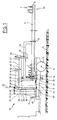
- the support 6 is transported to the storage surface 2 by means of a transporter device 10 according to the invention, which comprises a chassis 11 supporting at least one axle 12 with wheels 13, means 14, 15, 16 for association of the support 6 to this conveyor device 10, means 17, 18 for adjusting the position of the support 6 relative to the chassis 11, control and actuation means 21 of the means 7, 8, 34 for group unloading of the pots 1 from the support 6 , and various control and actuation means ensuring its operation.
- a transporter device 10 which comprises a chassis 11 supporting at least one axle 12 with wheels 13, means 14, 15, 16 for association of the support 6 to this conveyor device 10, means 17, 18 for adjusting the position of the support 6 relative to the chassis 11, control and actuation means 21 of the means 7, 8, 34 for group unloading of the pots 1 from the support 6 , and various control and actuation means ensuring its operation.
- the conveyor device 10 can be automotive or not. In the embodiment shown, it consists of a simple trailer towed by a tractor, and comprises a single axle 12 with two wheels 13.
- the support 6 is, like the storage beds 4, rectangular in shape.
- the support 6 When transporting the support 6 to the storage surface 2 and in the access aisles 3, that is to say from the potting machine to the storage bed 4, the support 6 is arranged for s 'extend lengthwise along the advancement axis 19 of the conveyor device 10 ( Figures 1 and 2).
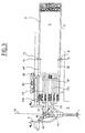
- the conveyor device 10 is advanced in an access aisle 3 of the storage surface 2 opposite a flower bed 4 of this surface 2 which extends perpendicular to the aisle 3, and the support 6 is placed ( by acting on the means 17, 18 for adjusting the position of the support 6 relative to the chassis 11) above and facing this strip 4, by pivoting this support 6 by approximately 90 ° relative to the chassis 11 in a at least substantially horizontal plane, in order to unload the pots 1 from the support 6.
- the conveyor device 10 comprises means 20 for positioning relative to the storage bed 4 on which the support 6 must be unloaded, and means 20 for stabilizing the conveyor device 10 ensuring stability during pivoting at 90 ° from support 6 and during unloading.
- the support 6 making it possible to transport a large number of pots 1 simultaneously and to put them in place without any other individual handling on a storage surface 2, is of the type comprising a chassis 30 and means 31 for holding the pots 1 in place, and is characterized in that it comprises means 7, 8, 34 for unloading grouped vertically downwards from the pots 1, these so-called means 7, 8, 34 for unloading making it possible to drop the pots 1 vertically in groups on the storage surface 2 without individual handling of these pots 1.
- the different means 7, 8, 34 for group unloading of the different pots 1 are mechanically linked together so that they can be actuated by a common actuating device 21.
- the means 31 for holding the pots 1 allow them to be stored in rows 32, and the unloading means 7, 8, 34 are arranged to allow grouped but progressive unloading of the pots 1, row by row, as a function of the movement stroke of the common actuating device 21.
- the support 6 has a rectangular bottom 8, which itself has recesses 7 forming traps for the passage of the pots 1, the said recesses 7 constituting the means 7 for group unloading of the pots 1.
- the bottom 8 is associated with the chassis 30 of the support 6 so as to be able to slide in a direction parallel to its plane and to that of the chassis, for example longitudinally relative to this chassis 30 between two positions: a normal position for which the recesses 7 do not come opposite the pots 1 which rest on the bottom 8, and an unloading position in which the recesses 7 are opposite the pots 1 and allow their vertical fall through these recesses 7 on the storage surface 2.
- the support 6 comprises fixed holding cross members 31 rigidly associated with the rectangular frame 30 parallel to one side 33 of the frame 30 - in particular parallel to a pe tit side 33 of this chassis 30 - and at a distance from each other so that the pots 1 can be arranged in rows 32 between these crosspieces 31.
- the bottom 8 consists of support crosspieces 34 of the pots 1 parallel to each other and to fixed sleepers holding 31, these support cross members 34 being spaced apart horizontally from one another so as to form recesses 7 between them allowing the passage of the rows 32 of pots 1 in the unloading position, when these recesses 7 are placed opposite the pots 1 by horizontal translation of the bottom 8 along its plane and perpendicular to the crosspieces 31, 34 and to the short side 33 of the frame 30 (FIG. 6a to 6c).
- the pots 1 are unloaded from the support 6 gradually by actuating the means 7, 8, 34 of unloading, starting with the pots 1 which are arranged in the vicinity of an extreme side 33 of the support 6, and ending with the pots 1 which are arranged in the vicinity of the opposite extreme side 35.
- the support 6 makes it possible to arrange the pots 1 in rows 32 parallel to the short side 33, 35 of this support 6.
- the pots are unloaded 1 row by row, so that this unloading is a grouped but progressive unloading.
- This characteristic is all the more important as the support 6 is long, because it makes it possible to avoid rocking of the support 6 during unloading, rocking which would risk damaging the pots 1 or the plants which they contain.
- the support 6 is characterized in that, in the normal position of the bottom 8 for which the pots 1 rest on the support sleepers 34, the distance d3 separating each support sleeper 34 of the fixed holding cross member 31 under which it slides in the unloading position, is different from one support cross member 34 to the other and varies gradually from one side 33 to the other 35 of the chassis 30, so that 'during the sliding of the bottom 8 from the normal position to the unloading position, the recesses 7 come opposite the pots 1 gradually from one side 33 to the other 35 of the frame 30.
- the fixed support 31 and mobile support cross-members 34, and therefore the rows 32 of pots 1 are parallel to the short sides 33, 35 of the rectangular frame 30 of the support 6.
- the support 6 also advantageously comprises means 36 for returning the bottom 8 to the normal position for which each support cross member 34 can support a row 32 of pots 1.
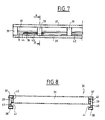
- the chassis 30 of the support 6 is for example made up of two peripheral rectangular frames 37 , 38, of the same size, placed one above the other and at a distance from one another by means of spacers 39 regularly distributed around the periphery between two frames 37, 38.
- Two longitudinal beams 40 associated under the large longitudinal beams of the upper frame 37 are provided.
- the fixed holding crosspieces 31 are rigidly associated with and perpendicular to these beams 40 and to the large longitudinal beams of the upper frame 37.
- the lower frame 38 projects slightly inwardly inward relative to the spacers 39 so as to form, with the longitudinal beams 40, ramps 41 for supporting and sliding the movable bottom 8. Skids 42 facilitating this sliding can be provided regularly distributed on the ramps 41 ( Figures 7 and 8).
- the means 36 for returning the bottom 8 to the normal position may consist of a spiral spring 36 associated by one of its ends with a support rod 43, itself fixed on a spacer 39.
- the rod 43 and the spring 36 s 'extend substantially horizontally and longitudinally.
- the other end of the spring 36 cooperates with a projection 44 on the bottom 8.
- Such springs 36 can be provided on each longitudinal side of the chassis 30.
- the means 14, 15, 16 for associating the support 6 with this conveyor device 10 are quick and removable attachment means.
- several supports 6 can be used.
- the support 6 being loaded at the outlet of the potting machine is placed on a table, in particular a roller table.
- the empty support 6 is removed and the support 6 which has just been loaded is hooked.
- Two separate tables superimposed, side by side, or on either side of the potting machine can be used to facilitate hooking / unhooking maneuvers.
- the means 14, 15, 16 for associating the support 6 with the conveyor device 10 comprise an attachment lifter 16 of the support 6, this attachment lifter 16 itself being suspended from the chassis 11 of the conveyor device 10 via means 17, 18 for adjusting the position of the support 6 by relative to chassis 11.
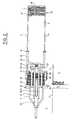
- the means 17, 18 for adjusting the position of the support 6 relative to the chassis 11 consist of an orientation bracket 18 associated with a bracket support 22 itself rigidly associated with the chassis 11, the bracket 18 of orientation being associated with this bracket support 22 so as to be able to pivot about a vertical axis 23.
- the means 17, 18 for adjusting the position of the support 6 relative to the chassis 11 also consist of a beam for adjusting height 17 extending horizontally suspended and parallel to the horizontal arm 24 of the orientation bracket 18 in an adjustable manner in height, the lifting beam 16 of the support 6 itself being suspended from the height adjustment beam 17.
- the lifting beam 16 of the support 6 is suspended from the height adjustment beam 17 by means 25, 26 allowing a variation in the inclination of this lifting beam 16 relative to this adjustment beam 17, this is -to-di re with respect to the horizontal.
- These means 25, 26 consist in particular on the one hand of an articulation 25 of the lifting beam 16 at a point of the beam 17 distant from its free end 27, and on the other hand of a jack 26 associated at least substantially vertical at the free end 27 of the beam 17.
- the height adjustment beam 17 is itself associated with the orientation bracket 18 on the one hand by a recess 45 of vertical axis at the end of this beam 17 cooperating with the vertical arm 29 of the bracket 18, and on the other hand thanks to a cable 46 anchored at two points 47, 48 to the beam 17 and passing through a series of pulleys 49, 50, 51 secured to the bracket 18 so that the cable 46 extends towards the down from an anchor point 47 on the beam 17, and extends upwards from the second anchor point 48 on the beam 17.
- a cable 46 anchored at two points 47, 48 to the beam 17 and passing through a series of pulleys 49, 50, 51 secured to the bracket 18 so that the cable 46 extends towards the down from an anchor point 47 on the beam 17, and extends upwards from the second anchor point 48 on the beam 17.
- the cable 46 is anchored at 47 at the end 28 of the beam 17 cooperating with the vertical arm 29 of the bracket 28, is recalled downwards by a pulley 49 arranged in lower part of the vertical arm 29, then is recalled in the upper part of this vertical arm 29 by a pulley 50 articulated at the corner of association of the vertical arm 29 and the horizontal arm 24 of the bracket 18, then extends horizontally to the free end 52 of the horizontal arm 24 by means of a pulley 51 disposed at this end 52, and finally extends vertically downwards to its second anchor point 48 on the beam 17.
- the actuating rod 55 of the jack 53 can be associated directly with the beam 17, but it is preferred to associate it at 56 with the lowest part of the lifting beam 16, in order to obtain the largest possible travel travel, without the body 54 of this jack 53 having to protrude vertically upwards from the stem 18.
- the body 54 of the jack 53 is associated articulated with the arm 24 of the stem 18 so as not to hinder the inclination of the lifter 16.
- the cable 46 being of constant length, it is easy to observe that when the jack 53 is actuated, the height adjustment beam 17 and the lifting beam 16 which is associated with it descend or rise, this beam 17 remaining constantly horizontal.
- a vertical recess is provided in the beam 17 to allow the free passage of the jack 53.
- the beam 17 consists of two horizontal beams 17a, 17b of the same level parallel and spaced from one another by a distance corresponding substantially to the width of the vertical arm 29 of the bracket 18.
- the articulation 25 of the lifter 16 on the beam 17 is arranged in the vicinity of the vertical axis of the jack 53, for example slightly in front of this axis.
- the actuating cylinder 26 allowing the inclination of the lifter 16 relative to the beam 17 is on the contrary rigidly associated vertically with the free end 27 of this beam 17, its body 57 projecting upwards from the beam 17 in order to '' obtain the sufficient travel travel of the actuating rod 58 of this cylinder 26.
- two safety hooks 59 secured to the free end 27 of the beam 17 extend downward to form a stop limiting the inclination of the lifter 16 relative to the horizontal and the deflection stroke of the jack 26 downwards.
- the bracket support 22 consists of a vertical mast substantially the same height as the vertical arm 29 of the bracket 18.
- a horizontal plate 60 extends from the free end 61 of the vertical mast 22 to form, at its free end 62, an upper articulation point of the bracket 18.
- the vertical arm 29 of the bracket 18 can be directly articulated to the chassis 11.
- the bracket 18 also includes a lower horizontal actuating arm 64 s' extending substantially horizontally from the lower end of the vertical arm 29 of the bracket 18. By acting at the free end of the lower horizontal arm 64, the bracket 18 can be pivoted about the vertical axis 23.
- the upper horizontal arm 24 of the bracket 18 is not shown, and this to better show the means for pivoting the bracket 18.
- These means consist of a rigid arm 65 articulated by one of its ends to the chassis 11 substantially under the vertical axis 23 of pivoting of the bracket 18, and articulated at its other end to the body of an actuating cylinder 66 whose actuating rod is associated with the free end of the arm lower horizontal actuation 64 of the bracket 18.
- the position of the rigid arm 65 relative to the chassis 11 is imposed and can be adjusted by means of a jack 67 extending perpendicular to the advancement axis 19 of the device conveyor 10, the body of which is integral with the chassis 11, and the actuating rod of which is articulated at a point on the rigid arm 65.
- This jack 67 makes it possible to place the rigid arm 65 either inclined to the left or inclined to the right e, which makes it possible to pivot the orientation bracket 18 respectively either to the right or to the left from its normal position in which it is placed along the advancement axis 19 of the conveyor device 10.
- the support 6 is placed above and opposite the flower bed 4 of the storage surface 2 at a distance from this flower bed 4 at least substantially constant along the support 6, as low as possible to allow actuation of the means 7, 8, 34 of unloading without damaging the pots 1, these unloading means 7, 8, 34 are actuated in order to cause the pots 1 to fall onto the storage surface 2, and the support 6 is replaced in an at least substantially horizontal plane and at a height sufficient to again allow it to pivot and be replaced along the advancement axis 19 of the conveyor device 10, and this without interference with the pots 1 or with their content.
- FIG. 6b illustrates the progressive unloading of the pots 1 by actuation of the unloading means 7, 8, 34.
- FIG. 6c the support 6 is raised upwards until it no longer interferes with the pots 1 or with the plants it contains, so that it can be replaced along the axis 19 d advancement of the conveyor device 10.
- the conveyor device 10 comprises on each side a stand 20 for stabilization and positioning.
- This stand is retractable and must be deployed before rotating the bracket 18 and the support 6 perpendicular to the advancement axis 19.
- the conveyor device 10 is advanced in the aisle of access 3 until the stand 20 comes opposite an access path 5 which serves as a reference point between two storage beds 4.
- the support 6 can then be pivoted without risk of the conveyor device 10 tilting to the side.
- the retraction and deployment of the stabilizing and positioning crutches 20 is carried out by means of jacks, or simply by hand.
- a jack 68 for blocking the deployed stand 20, and for adjusting the attitude of the conveyor device 10 can be provided.
- the sleeve 75 of each stand 20 is articulated on one side of the frame 11 by one end 76 and the jack 68 extends vertically on the other side between the frame 11 and the other end 77 of the sleeve 75 for adjust the inclination from the horizontal.
- the attachment lifter 16 comprises on the one hand at least one projection 14 penetrating into an extreme edge 33 of the support 6, between two spacers 39, and on the other hand two bent arms 69 symmetrical with respect to each other to a vertical plane, cooperating via fastening devices 15 respectively with the two lateral edges 71 of the support 6 at points 72 of these lateral edges 71 distant from the extreme edge 33 cooperating with the projection 14.
- the attachment devices 15 may consist of simple hooks articulated at the lower free end of each of the two bent arms 69, and cooperating with the upper frame 37 of the support 6.
- the chassis 11 advantageously comprises lateral centering lugs facilitating the positioning of the support on the chassis 11 along the advancement axis 19 of the conveyor device 10.
- FIGS. 6a to 6c The operation of the means 21 for actuating the unloading means 7, 8, 34 is illustrated in FIGS. 6a to 6c.
- These actuating means 21 may consist of a bent lever 21a and an actuating cylinder 21b.
- the lever 21a is associated with the lifting beam 16, and its free end 73 cooperates with the most extreme support cross member 34 and closest to the end edge 33 of the support 6.
- the lever 21a is also associated with the actuator actuation 21b.
- the lever 21a is associated articulated by one of its ends to the lifting beam 16 and is bent twice.
- the actuating rod of the jack 21b is associated articulated with one of the codes of this lever 21a.
- the set of jacks 26, 53, 66, 67, 68, 21b is supplied with hydraulic and / or hydro-pneumatic energy by the tractor device via centralized control means 74 with valves arranged at the front of the conveyor device 10.
- the invention allows with a conveyor device 10 of great simplicity and low cost to simultaneously transport a very large number of pots with a very long support. A single person can thus almost instantly fill a complete storage bed 4.
- the spacing E1 between two holding crosspieces 31 is adapted as a function of the size of pots 1. It is possible to provide a value of E1 for two dimensions of pots 1. The tests carried out have shown that it is possible to immediately fill plates -storage strips 4 whose dimensions are of the order of 7 m by 1.5 m with pots 1 of 1 liter to 5 liters.
- E1 ⁇ 147 mm, e1 ⁇ 70 mm, e2 ⁇ 60 mm, d2 ⁇ 216 mm can be provided, and thirty rows 32 of pots 1 are thus formed for a length of the support. 6 of the order of 6780 mm and a width of the order of 1460 mm.
- E1 ⁇ 180 mm, e1 ⁇ 60 mm, d2 ⁇ 259 mm can be provided, and twenty-five rows 32 of pots 1 are thus formed for a length of the support 6 of the order of 6760 mm and a width of 1460 mm.
- This wedging cross member can be produced by a simple vertical plate associated with the retaining cross member 31 by upper brackets comprising lugs extending downward and which cooperate with bores in the upper part of the retaining cross member 31.
- Such a wedge also has the advantage of avoiding the overturning of the pots on unloading and ensuring vertical unloading.
- the total height of the conveyor device 10, that is to say the height between the ground and the free end 61 of the mast 22 of the bracket support, is of the order of 2500 mm.
- the length of the height adjustment beam 17 is of the order of 2750 mm.
- the length of the lifter 16 is of the order of 3000 mm.
- the point 25 of articulation of the spreader 16 to the beam 17 is distant from the free end 27 of this beam 17 by about 1600 mm.
- the support 6 When the invention is used to transport the pots 1 from the culture surface to an order preparation surface, the support 6 is placed above a flower bed 4 adjoining the flower bed 4 of which we take the pots 1, at a height sufficient not to damage the plants of this flower bed 4. We can load the support 6 in pots 1 very quickly and easily, manually, because the distance to be made at each pot is weak.
Landscapes
- Life Sciences & Earth Sciences (AREA)
- Environmental Sciences (AREA)
- Cultivation Receptacles Or Flower-Pots, Or Pots For Seedlings (AREA)
Claims (12)
Applications Claiming Priority (2)
| Application Number | Priority Date | Filing Date | Title |
|---|---|---|---|
| FR8710906 | 1987-07-31 | ||
| FR8710906A FR2618637B1 (fr) | 1987-07-31 | 1987-07-31 | Procede, support et dispositif pour transporter simultanement un grand nombre de pots sur une surface de stockage horticole |
Publications (2)
| Publication Number | Publication Date |
|---|---|
| EP0304364A1 EP0304364A1 (de) | 1989-02-22 |
| EP0304364B1 true EP0304364B1 (de) | 1992-02-05 |
Family
ID=9353779
Family Applications (1)
| Application Number | Title | Priority Date | Filing Date |
|---|---|---|---|
| EP19880401980 Expired - Lifetime EP0304364B1 (de) | 1987-07-31 | 1988-07-29 | Verfahren, Stütze und Transportiervorrichtung zum gleichzeitigen Transportieren einer grossen Zahl von Töpfen auf einer gartenbaulichen Lagerungsfläche |
Country Status (3)
| Country | Link |
|---|---|
| EP (1) | EP0304364B1 (de) |
| DE (1) | DE3868303D1 (de) |
| FR (1) | FR2618637B1 (de) |
Families Citing this family (6)
| Publication number | Priority date | Publication date | Assignee | Title |
|---|---|---|---|---|
| AU1572099A (en) * | 1997-12-16 | 1999-07-05 | Samuel James Harrison | Positioning technique for horticultural apparatus |
| CN107933418B (zh) * | 2017-11-25 | 2020-08-07 | 李金领 | 一种树木拖运设备 |
| CN107962999A (zh) * | 2017-11-25 | 2018-04-27 | 杨艳 | 一种拉树设备 |
| CN107933407A (zh) * | 2017-11-25 | 2018-04-20 | 杨艳 | 一种树木吊运车 |
| CN107972550B (zh) * | 2017-11-25 | 2020-09-01 | 江西省炎伟丞实业有限公司 | 一种道路绿化施工设备 |
| CN114009240B (zh) * | 2021-11-04 | 2023-10-03 | 常熟市佳盛农业科技发展有限公司 | 一种盆栽架放置装置和放置方法 |
Family Cites Families (4)
| Publication number | Priority date | Publication date | Assignee | Title |
|---|---|---|---|---|
| US3078020A (en) * | 1962-04-04 | 1963-02-19 | Richard N Boonstra | Horticultural carrying apparatus |
| FR2137326B1 (de) * | 1971-05-18 | 1973-05-11 | Cramer Maschf | |
| US4003185A (en) * | 1975-06-06 | 1977-01-18 | Otis Ward Goff | Caser apparatus |
| DE3625674C1 (en) * | 1986-07-16 | 1987-05-27 | Geraetebau Soester Boerde Gmbh | Device for transporting and depositing plants arranged in pots or the like |
-
1987
- 1987-07-31 FR FR8710906A patent/FR2618637B1/fr not_active Expired - Fee Related
-
1988
- 1988-07-29 DE DE8888401980T patent/DE3868303D1/de not_active Expired - Lifetime
- 1988-07-29 EP EP19880401980 patent/EP0304364B1/de not_active Expired - Lifetime
Also Published As
| Publication number | Publication date |
|---|---|
| FR2618637A1 (fr) | 1989-02-03 |
| DE3868303D1 (de) | 1992-03-19 |
| FR2618637B1 (fr) | 1994-02-04 |
| EP0304364A1 (de) | 1989-02-22 |
Similar Documents
| Publication | Publication Date | Title |
|---|---|---|
| US7353635B2 (en) | Tree root ball wrapping apparatus and method of using same | |
| EP0318406B1 (de) | Anpfählmaschine für Wein oder andere Pflanzen oder Bäumchen und Spange wie sie von dieser Maschine benutzt wird | |
| FR2695001A1 (fr) | Machine à vendanger et à récolter les raisins secs radiale à équilibrage de force automatique. | |
| FR2705525A1 (fr) | Machine à vendanger les raisins frais et secs d'une seule rangée de pieds de vigne. | |
| EP2173150B1 (de) | Vorrichtung zum schneiden von zuckerrohr | |
| US6282878B1 (en) | Produce catcher | |
| FR2941594A1 (fr) | Machine agricole pour derouler et poser un film ou voile, notamment en grande largeur, sur des cultures, et utilisation de celle-ci pour le deroulement et la pose d'un film sur des cultures. | |
| EP0304364B1 (de) | Verfahren, Stütze und Transportiervorrichtung zum gleichzeitigen Transportieren einer grossen Zahl von Töpfen auf einer gartenbaulichen Lagerungsfläche | |
| EP0243264A1 (de) | Pflanzmaschine und Verfahren zum pflanzen für Setzlinge in Topfballen | |
| FR2939274A1 (fr) | Tete de recolte et machine automotrice enjambeuse en faisant application, utilisables pour la recolte des haies fruitieres | |
| FR2647628A1 (fr) | Machine pour deterrer, couper les fanes et les racines et conditionner l'ail | |
| EP0502789A1 (de) | Maschine zum Ernten von Brokkoli | |
| FR2522245A1 (fr) | Materiel agricole pour la recolte de fruits et ensembles recepteurs constitutifs dudit materiel | |
| FR2987222A1 (fr) | Dispositif mecanise pour planter des plants | |
| EP0465327A2 (de) | Vorrichtung für die Errichtung von Kulturtunneln | |
| FR2880772A1 (fr) | Installation de protection pour culture palissee, en rang | |
| FR2542156A1 (en) | Grape harvesting machine consisting of a straddling tractor | |
| EP0576336B1 (de) | Modul zur Behandlung, für die erdlose Kultur (insbesondere in Gewächshäusern), für den Transport und Verkauf von Gemüse, Früchten oder Blumen | |
| US5306114A (en) | Elevating scaffold trailer | |
| NL2023335B1 (en) | Apparatus and method for harvesting tubers or bulbs | |
| FR3061829B1 (fr) | Dispositif de recolte de rhizomes de miscanthus equipe de moyens de fractionnement | |
| FR2740151A1 (fr) | Module de gazon pour la realisation d'une pelouse amovible et procede d'amenagement de stade mettant en oeuvre plusieurs de ces modules | |
| FR2537828A1 (fr) | Installation mobile d'assistance a la recolte manuelle des fruits ou des legumes | |
| FR2749003A1 (fr) | Machine destinee au debardage des caisses de fruits pendant la recolte ou la cueillette dans les plantations | |
| FR2738988A1 (fr) | Machine automatique permettant de realiser le depotage et rempotage de plants et dispositif permettant la manutention desdits plants utilisables sur une telle machine |
Legal Events
| Date | Code | Title | Description |
|---|---|---|---|
| PUAI | Public reference made under article 153(3) epc to a published international application that has entered the european phase |
Free format text: ORIGINAL CODE: 0009012 |
|
| AK | Designated contracting states |
Kind code of ref document: A1 Designated state(s): BE DE IT NL |
|
| 17P | Request for examination filed |
Effective date: 19890419 |
|
| 17Q | First examination report despatched |
Effective date: 19901123 |
|
| GRAA | (expected) grant |
Free format text: ORIGINAL CODE: 0009210 |
|
| AK | Designated contracting states |
Kind code of ref document: B1 Designated state(s): BE DE IT NL |
|
| PG25 | Lapsed in a contracting state [announced via postgrant information from national office to epo] |
Ref country code: IT Free format text: LAPSE BECAUSE OF FAILURE TO SUBMIT A TRANSLATION OF THE DESCRIPTION OR TO PAY THE FEE WITHIN THE PRE;WARNING: LAPSES OF ITALIAN PATENTS WITH EFFECTIVE DATE BEFORE 2007 MAY HAVE OCCURRED AT ANY TIME BEFORE 2007. THE CORRECT EFFECTIVE DATE MAY BE DIFFERENT FROM THE ONE RECORDED.SCRIBED TIME-LIMIT Effective date: 19920205 Ref country code: NL Effective date: 19920205 |
|
| REF | Corresponds to: |
Ref document number: 3868303 Country of ref document: DE Date of ref document: 19920319 |
|
| NLV1 | Nl: lapsed or annulled due to failure to fulfill the requirements of art. 29p and 29m of the patents act | ||
| PG25 | Lapsed in a contracting state [announced via postgrant information from national office to epo] |
Ref country code: BE Effective date: 19920731 |
|
| PLBE | No opposition filed within time limit |
Free format text: ORIGINAL CODE: 0009261 |
|
| STAA | Information on the status of an ep patent application or granted ep patent |
Free format text: STATUS: NO OPPOSITION FILED WITHIN TIME LIMIT |
|
| 26N | No opposition filed | ||
| BERE | Be: lapsed |
Owner name: THOMAS GEORGES Effective date: 19920731 |
|
| PGFP | Annual fee paid to national office [announced via postgrant information from national office to epo] |
Ref country code: DE Payment date: 19960131 Year of fee payment: 8 |
|
| PG25 | Lapsed in a contracting state [announced via postgrant information from national office to epo] |
Ref country code: DE Effective date: 19970402 |