EP0303577B1 - Automatisch arbeitende Einrichtung zum Auswechseln von Vorgarnspulen in einer Spinnmaschine für Textilfasern - Google Patents
Automatisch arbeitende Einrichtung zum Auswechseln von Vorgarnspulen in einer Spinnmaschine für Textilfasern Download PDFInfo
- Publication number
- EP0303577B1 EP0303577B1 EP88830333A EP88830333A EP0303577B1 EP 0303577 B1 EP0303577 B1 EP 0303577B1 EP 88830333 A EP88830333 A EP 88830333A EP 88830333 A EP88830333 A EP 88830333A EP 0303577 B1 EP0303577 B1 EP 0303577B1
- Authority
- EP
- European Patent Office
- Prior art keywords
- rove
- roves
- spinning
- cylinder
- supplied
- Prior art date
- Legal status (The legal status is an assumption and is not a legal conclusion. Google has not performed a legal analysis and makes no representation as to the accuracy of the status listed.)
- Expired
Links
- 238000009987 spinning Methods 0.000 title claims description 87
- 239000004753 textile Substances 0.000 title claims description 4
- 238000011144 upstream manufacturing Methods 0.000 claims description 4
- 239000013536 elastomeric material Substances 0.000 claims 1
- 230000036961 partial effect Effects 0.000 description 4
- 210000002268 wool Anatomy 0.000 description 2
- 239000000470 constituent Substances 0.000 description 1
- 238000006073 displacement reaction Methods 0.000 description 1
- 230000002452 interceptive effect Effects 0.000 description 1
- 230000000670 limiting effect Effects 0.000 description 1
- 238000000034 method Methods 0.000 description 1
- 230000002829 reductive effect Effects 0.000 description 1
- 230000002441 reversible effect Effects 0.000 description 1
Images


Classifications
-
- D—TEXTILES; PAPER
- D01—NATURAL OR MAN-MADE THREADS OR FIBRES; SPINNING
- D01H—SPINNING OR TWISTING
- D01H9/00—Arrangements for replacing or removing bobbins, cores, receptacles, or completed packages at paying-out or take-up stations ; Combination of spinning-winding machine
- D01H9/005—Arrangements for replacing or removing bobbins, cores, receptacles, or completed packages at paying-out or take-up stations ; Combination of spinning-winding machine for removing empty packages or cans and replacing by completed (full) packages or cans at paying-out stations; also combined with piecing of the roving
-
- D—TEXTILES; PAPER
- D01—NATURAL OR MAN-MADE THREADS OR FIBRES; SPINNING
- D01H—SPINNING OR TWISTING
- D01H15/00—Piecing arrangements ; Automatic end-finding, e.g. by suction and reverse package rotation; Devices for temporarily storing yarn during piecing
Definitions
- the present invention relates to spinning machines for spinning textile fibres of any type, particularly for spinning carded fibres, in which the spinning machine is supplied with one or more roves, and in which a plurality of roves wound in the form of so-called "rolls" is supplied to spinning devices adapted to subject the roves to drawing and twisting.
- variable numbers of rolls are generally wound onto supporting rods and, together with the latter, form the so-called "cylinder".
- each rove, coming from its respective roll, is supplied from the cylinder to the drawing and twisting device along a corresponding spinning line and is then wound onto the respective spindle situated at the end of the spinning line.
- the spinning machines normally include several spinning sections, each of which includes a feed cylinder, the cylinder-changing operation generally involves a fairly long stoppage of the spinning machine.
- This patent describes means for positioning the full cylinder in its parking position and means for holding the ends of the roves supplied by the full cylinder in predetermined positions, the ends being brought into positions adjacent the roves of the respective spinning lines at the end of the changeover.
- the object of the present invention is to produce a spinning machine in which the above operations for the joining of the corresponding roves to the respective spinning lines and their detachment therefrom are carried out automatically, that is, without the direct intervention of the operator.
- the technical problem which must be addressed and resolved is not only that of achieving the mechanical joining of a single rove to the respective spinning line and its detachment therefrom, but the more complex problem of achieving the substantially simultaneous joining of all the roves of the full cylinder and the substantially simultaneous detachment of all the roves of the used cylinder.
- the subject of the invention is a device for automatically achieving, in a spinning machine for spinning textile fibres of any type, particularly for spinning carded fibres, in which the spinning machine is supplied by one or more roves, the detachment from the respective spinning lines of the roves supplied by the used cylinder arranged on the spinning machine in an operative supply position and rotated for unwinding by a mechanism which is driven by a motor unit, and the corresponding joining of the roves supplied by a full cylinder arranged on the spinning machine in an initial parking position and intended to replace the used cylinder in the operative supply position, the device comprising means for holding the ends of the roves supplied by the full cylinder in a predetermined position and means for the bringing together and joining of the end of each rove of the full cylinder and the rove of the respective spinning line, characterised in that the means for the bringing together and joining of the end of each rove of the full cylinder and the rove
- a machine for spinning carded wool is indicated 1 and comprises a fixed base frame 2 housing within it the motor unit which operates the spinning machine.
- the cylinder 4 is guided and held in position by slots 3a which cooperate with end pins of the cylinder 4.
- the rove 4a of each roll of the cylinder 4 is fed along a spinning line 5 to a corresponding drawing and twisting unit 6 and is subsequently wound onto a corresponding spindle 7 situated at the end of the respective spinning line 5.
- a transporter unit 8 is situated on the upper part of the spinning machine 1 and includes a linear conveyor 9.
- Two vertical support shafts supported by the conveyor 9 are indicated 10 and have hook-shaped appendages 10a at their lower ends.
- a full cylinder 11 is suspended from the support shafts 10.
- This cylinder 11 comprises a rod 12 onto which a plurality of rolls 13 are wound for connection to the spinning line 5.
- the rod 12 has a pin 14 which is coupled with the hook-shaped end 10a of the shaft 10 carried by the conveyor 9.
- Two rigid arms, indicated 15, which are side by side, are keyed to a shaft 16 carried rotatably by the fixed structure of the transporter device 8 and rotated by known means, for example, hydraulic jacks or the like, not illustrated.
- Each arm 15 is provided with an inclined and bent guide plate which forms a supporting seat 17 for engaging the end pins 14 of the rod 12 of the full cylinder 11.
- the supporting seat 17 is V-shaped in cross-section and includes a first section 17a and a second section 17b which is inclined to the first.
- Each arm 15 also has a bent terminal part 18 on the end of which a plate 19 is situated.
- a support structure, indicated 20, is provided with two arms 20a fixed firmly to a shaft 21 carried rotatably by the rigid frame of the device 8 and also rotated by known means, not illustrated.
- the arms 20a are connected by a cross bar 22 on which clamps 23 are fixed.
- Each clamp 23 carries a gripper 24 on its front face.
- the gripper 24 comprises an articulated jaw 25 supported by the respective clamp 23 for rotation about an articulation axis 26.
- the articulated jaw 25 is provided with two engagement faces 27 and 28 which cooperate with two corresponding fixed seats 29 and 30 of a magnetic plate 31.
- the articulated jaw 25 has an end appendage 32 formed in a position adjacent the engagement face 27.
- Each clamp 23 has a thread guide 33 in a position opposite the jaw 25 and constituted by a bent and shaped plate provided with a notch which has an initial V-shaped entry section 34.
- a C-shaped plate, indicated 35, holds a rubber block 36 tightly against the respective clamp 23.
- the spinning machine 1 also has an elongate bar 37 which is T-shaped in section and whose upper face is covered by a rubber strip 38 forming a flat support or base.
- the bar 37 can slide longitudinally in both directions and its translational movement is effected by a tie-rod 39a driven by an actuator 39.
- the bar 37 also has pins 37a on its front face, each of which cooperates with the end appendage 32 of a respective articulated jaw 25.
- the rove of each roll 13 of the full cylinder is indicated 40 and the end of the rove 40 is indicated 41.
- the end section of the rove 40 near the end 41 is indicated 42.
- the roller 3 is driven by a shaft 43 by means of a drive and reversing unit 44 which receives drive from a motor unit 45.
- the drive and reversing unit 44 has a gear 46 which is rotated in the sense corresponding to the unwinding of the cylinder 4 which supplies the roves of the spinning line 5.
- the unit 44 also includes a second gear 47 which receives drive from a gear 49 by means of a chain 48. The gear 47 is rotated in the opposite sense to the gear 46.
- a flange 50 provided with frontal dog clutches 51 and 52 is interposed between the gear 46 and the gear 47.
- the flange 50 can be displaced parallel to itself by an operating fork 53.
- the flange 50 can thus be brought into engagement with the gear 46 by means of the clutch 51 or with the gear 47 by means of the clutch 52, so that it can be rotated in one sense of rotation or the other.
- the flange 50 is coupled torsionally to the shaft 43 and transmits the rotary drive thereto.
- the device operates as follows.
- the cylinder 4 is in its operative supply position in which the roves coming from its rolls supply the corresponding spinning lines 5. Whilst the spinning machine is operating, the conveyor, with its two shafts 10, supplies a full cylinder 11 and places it in a position above the cylinder 4 which is being unwound.
- the spinning machine 1 generally includes several spinning sections, each of which is provided with a cylinder 4 whose rolls supply respective spinning lines 5 to respective drawing unit 6 spindles 7 through corresponding drawing units: in this case, the conveyor 9 supplies a full cylinder 11 in correspondence with each cylinder 4.
- the rigid arms 15 of each section of the spinning machine are raised until the first section 17a of the inclined support seat 17 is brought into engagement with the relative end pin 14 carried by the rod 12 of the respective cylinder 11.
- the pins 14 of the cylinder 11 are thus raised so that they are disengaged from the hooked ends 10a of the vertical shafts 10 of the conveyor 9.
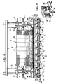
- the pins 14 then slide along the section 17a and are positioned in correspondence with the junction between the sections 17a and 17b of the seat 17 (as shown in broken outline in Figure 13).
- the cylinder 11 can subsequently be lowered by the rigid arms 15 into a parking position, shown in Figure 3, without interfering with the hooks 10a.
- the operator takes the rove 40 of each roll 13 of the full cylinder 11, passes it through the thread guide 33 carried by the respective clamp 23, and clamps its end 41 by means of the corresponding articulated jaw 25.
- the jaw 25 clamps the end 41 of the corresponding rove 40 between its engagement face 27 and the corresponding fixed seat 29 of the respective magnetic plate 31.
- the end section 42 of the rove 40 is thus arranged in a predetermined position fixed by the guiding action of the thread guide 33 in combination with the clamping action of the jaw 25.
- This operation is repeated for the rove 40 of each roll 13. At the end of this operation, therefore, all the ends 41 of the roves from the rolls 13 of the full cylinder 11 are clamped by respective corresponding jaws 25.
- each cylinder 4 which is being unwound is almost finished and each cylinder 4 is therefore used up, the operator intervenes by stopping the spinning machine.
- the support structure 20 which carries the grippers 24 with the respective jaws 25 is lowered by the action of drive means until the grippers have moved down onto the elongate bar 37.
- each of the various thread guides 33 engages the rove of the corresponding spinning line 5.
- the action of the thread guide 33 causes the rove of the corresponding spinning line 5 to be bent so that it lies on the rubber strip 38 carried by the elongate bar 37.
- All the roves 4a of all the spinning lines thus lie on the strip 38 in positions beside the corresponding end sections 42 of the respective roves 40 from the full cylinder.
- the end section 42 of each rove 40 of the full cylinder is urged by the rubber block 36 against the corresponding rove of the respective spinning line 5 and is clamped to the strip 38 together therewith.
- the roller 3 is rotated in the opposite sense, that is, clockwise with reference to Figure 1, by the operation of the reversing device of the drive unit 44 to cause the detachment of the rove 4a of each roll of the used cylinder 4 from the spinning line 5.
- the rigid arms 15 are lowered further and their respective end plates 19 come into contact with the end pins of the rod of the used cylinder 4 to cause its ejection.
- the rod 12 of the used cylinder falls into a rear transporter and is conveyed by the latter to a suitable container.
- the end pins 14 of the full cylinder 11 come into contact with the guide slots 3a, causing the pins to be disengaged from the corresponding rigid arms 15.
- the cylinder 11 moves down into contact with the roller 3, guided by the slots 3a.
- the operator operates the actuator 39 to cause the translation of the bar 37 towards the left in Figure 8.
- the pins 37a carried by the bar 37 engage the corresponding appendages 32 of the respective articulated jaws 25, thus causing the relative grippers 24 to open.
- Each gripper 24 brings its engagement face 28 into contact with the corresponding fixed seat 30 of the respective magnetic plate 31 and is thus held in the open position.
- the longitudinal displacement of the bar 37 simultaneously causes the roves 42 and 5 which are beside each other to be twisted around each other, as illustrated in Figure 11.
- the rigid arms 15 and the structure 20 which carries the grippers 24 are raised into their respective starting positions (Fig. 13).
- the spinning lines 5, which unwind from the full cylinder now positioned in the supply position in place of the used cylinder 4, are now reset by the restarting of the spinning machine 1.
Landscapes
- Engineering & Computer Science (AREA)
- Mechanical Engineering (AREA)
- Textile Engineering (AREA)
- Spinning Or Twisting Of Yarns (AREA)
Claims (12)
Applications Claiming Priority (2)
| Application Number | Priority Date | Filing Date | Title |
|---|---|---|---|
| IT67703/87A IT1218670B (it) | 1987-08-10 | 1987-08-10 | Dispositivo per il cambio automatico delle cannelle in un filatoio per fibre tessili |
| IT6770387 | 1987-08-10 |
Publications (2)
| Publication Number | Publication Date |
|---|---|
| EP0303577A1 EP0303577A1 (de) | 1989-02-15 |
| EP0303577B1 true EP0303577B1 (de) | 1991-12-27 |
Family
ID=11304636
Family Applications (1)
| Application Number | Title | Priority Date | Filing Date |
|---|---|---|---|
| EP88830333A Expired EP0303577B1 (de) | 1987-08-10 | 1988-08-02 | Automatisch arbeitende Einrichtung zum Auswechseln von Vorgarnspulen in einer Spinnmaschine für Textilfasern |
Country Status (4)
| Country | Link |
|---|---|
| EP (1) | EP0303577B1 (de) |
| DE (1) | DE3867173D1 (de) |
| ES (1) | ES2028364T3 (de) |
| IT (1) | IT1218670B (de) |
Families Citing this family (6)
| Publication number | Priority date | Publication date | Assignee | Title |
|---|---|---|---|---|
| JP2784078B2 (ja) * | 1990-03-22 | 1998-08-06 | 豊和工業株式会社 | 精紡機における一斉篠継方法と装置 |
| US5343689A (en) * | 1990-03-22 | 1994-09-06 | Howa Machinery, Ltd. | Method and apparatus for synchronously piecing roving for a continuous feeding thereof to a ring spinning frame |
| JP2796420B2 (ja) * | 1990-10-18 | 1998-09-10 | 豊和工業株式会社 | 紡機の自動スライバー継ぎ方法 |
| DE4040531A1 (de) * | 1990-12-18 | 1992-07-02 | Rieter Ag Maschf | Luntenwechselvorrichtung |
| BE1007310A3 (fr) * | 1993-07-07 | 1995-05-16 | Houget Duesberg Bosson | Procede et dispositif pour rattacher deux fils dans un continu a filer. |
| ITUB20155494A1 (it) * | 2015-11-11 | 2017-05-11 | Gbs Srl 59100 Prato / It | Dispositivo automatico per la alimentazione dei subbi di stoppino in una filanda |
Family Cites Families (3)
| Publication number | Priority date | Publication date | Assignee | Title |
|---|---|---|---|---|
| CH383228A (de) * | 1960-12-07 | 1964-10-15 | Rieter Ag Maschf | Selbsttätige Bandeinzugsvorrichtung |
| ATE43865T1 (de) * | 1985-03-27 | 1989-06-15 | Bigagli Fond Off | Verfahren und vorrichtung zum wechseln von faserbandwickeln mit automatischer faserbandanknuepfung an spinnmaschinen fuer kardierte wolle. |
| EP0213962B1 (de) * | 1985-09-04 | 1991-09-04 | Howa Machinery Limited | Verfahren und Vorrichtung zum Verbinden von Vorgarn in Spinnmaschinen |
-
1987
- 1987-08-10 IT IT67703/87A patent/IT1218670B/it active
-
1988
- 1988-08-02 EP EP88830333A patent/EP0303577B1/de not_active Expired
- 1988-08-02 ES ES198888830333T patent/ES2028364T3/es not_active Expired - Lifetime
- 1988-08-02 DE DE8888830333T patent/DE3867173D1/de not_active Expired - Fee Related
Also Published As
| Publication number | Publication date |
|---|---|
| DE3867173D1 (de) | 1992-02-06 |
| IT1218670B (it) | 1990-04-19 |
| EP0303577A1 (de) | 1989-02-15 |
| IT8767703A0 (it) | 1987-08-10 |
| ES2028364T3 (es) | 1992-07-01 |
Similar Documents
| Publication | Publication Date | Title |
|---|---|---|
| EP0258188B1 (de) | Verfahren zum Verbinden von Vorgarnsträngen und zum Auswechseln von Vorgarnspulen in einer Ringspinnmaschine und Vorrichtung zur Durchführung dieses Verfahrens | |
| EP0303577B1 (de) | Automatisch arbeitende Einrichtung zum Auswechseln von Vorgarnspulen in einer Spinnmaschine für Textilfasern | |
| EP0410016A1 (de) | Betriebsverfahren und Vorrichtung zur automatisierten Reinigung von Spulenhülsen von Fadenresten entlang einer textilen Fadenbearbeitungsmachine, insbesondere Doppeldraht-Zwirnmaschine, verfahrbare automatisierte Wartungs- und Bedienungsvorrichtung | |
| HU210119B (en) | Double-twist twisting machine for producing twisted articles | |
| US3904050A (en) | Automatic apparatus for supplying laps to a group of combers | |
| EP0716169B1 (de) | Kreuzspulen herstellende Textilmaschine | |
| US5473879A (en) | Open-end spinning machine for producing cross-wound bobbins | |
| EP0361306B1 (de) | Automatisches Ansetzen eines Faserbandes in einer Textilmaschine | |
| US4178748A (en) | Open-end spinning machine apparatus with a traveling device for bobbin exchange and method of using same | |
| US4923132A (en) | Doffing truck for a yarn false twisting machine | |
| CS368290A2 (en) | Method and device for automatized bobbins especially cross-wound bobbins with doubled yarn for empty bobbins | |
| JP4478344B2 (ja) | チーズを製作する紡織機の作業箇所の運転を開始する装置 | |
| US5495991A (en) | Apparatus for transporting empty yarn winding tubes and fully wound textile yarn packages to and from a winding location | |
| US4651515A (en) | Procedure and device to change roving packages, with automatic re-attachment of the roving on machines to spin carded wool | |
| US4890358A (en) | System for automatically conveying cotton laps from a ribbon-lap machine to a combing machine assembly | |
| DE19858986A1 (de) | Bedienaggregat für eine Faserband verarbeitende Textilmaschine | |
| CN111403172B (zh) | 多轴自动套管机送线接管机构 | |
| EP0481922B1 (de) | Verfahren und Vorrichtung zum Faserbandansetzen | |
| US3765160A (en) | Mechanized bobbin handler | |
| DE69028654T2 (de) | Automatische Vorrichtung zur Inbetriebnahme einer Doppeldraht-Zwirnanlage nach dem Ausfall des Vorlagegarns. | |
| JPH0742030A (ja) | 精紡機の粗糸替方法及び粗糸替機 | |
| ITMI952122A1 (it) | Dispositivo e procedimento automatico per la sostituzione delle confezioni di teletta di alimentazione e per la preparazione e | |
| CN113844923B (zh) | 一种智能全自动分卷机 | |
| CZ289891A3 (en) | Method of handling wound-up bobbin in spindleless spinning machines and device for making the same | |
| CN213203307U (zh) | 一种基于agv车的须条接头装置 |
Legal Events
| Date | Code | Title | Description |
|---|---|---|---|
| PUAI | Public reference made under article 153(3) epc to a published international application that has entered the european phase |
Free format text: ORIGINAL CODE: 0009012 |
|
| AK | Designated contracting states |
Kind code of ref document: A1 Designated state(s): BE DE ES FR GB |
|
| 17P | Request for examination filed |
Effective date: 19890225 |
|
| 17Q | First examination report despatched |
Effective date: 19910221 |
|
| GRAA | (expected) grant |
Free format text: ORIGINAL CODE: 0009210 |
|
| AK | Designated contracting states |
Kind code of ref document: B1 Designated state(s): BE DE ES FR GB |
|
| PG25 | Lapsed in a contracting state [announced via postgrant information from national office to epo] |
Ref country code: FR Effective date: 19911227 |
|
| REF | Corresponds to: |
Ref document number: 3867173 Country of ref document: DE Date of ref document: 19920206 |
|
| EN | Fr: translation not filed | ||
| REG | Reference to a national code |
Ref country code: ES Ref legal event code: FG2A Ref document number: 2028364 Country of ref document: ES Kind code of ref document: T3 |
|
| PLBE | No opposition filed within time limit |
Free format text: ORIGINAL CODE: 0009261 |
|
| STAA | Information on the status of an ep patent application or granted ep patent |
Free format text: STATUS: NO OPPOSITION FILED WITHIN TIME LIMIT |
|
| 26N | No opposition filed | ||
| PG25 | Lapsed in a contracting state [announced via postgrant information from national office to epo] |
Ref country code: DE Effective date: 19930501 |
|
| PGFP | Annual fee paid to national office [announced via postgrant information from national office to epo] |
Ref country code: ES Payment date: 19950719 Year of fee payment: 8 |
|
| PG25 | Lapsed in a contracting state [announced via postgrant information from national office to epo] |
Ref country code: ES Free format text: LAPSE BECAUSE OF THE APPLICANT RENOUNCES Effective date: 19960803 |
|
| PGFP | Annual fee paid to national office [announced via postgrant information from national office to epo] |
Ref country code: GB Payment date: 19980721 Year of fee payment: 11 |
|
| PGFP | Annual fee paid to national office [announced via postgrant information from national office to epo] |
Ref country code: BE Payment date: 19980813 Year of fee payment: 11 |
|
| PG25 | Lapsed in a contracting state [announced via postgrant information from national office to epo] |
Ref country code: GB Free format text: LAPSE BECAUSE OF NON-PAYMENT OF DUE FEES Effective date: 19990802 |
|
| PG25 | Lapsed in a contracting state [announced via postgrant information from national office to epo] |
Ref country code: BE Free format text: LAPSE BECAUSE OF NON-PAYMENT OF DUE FEES Effective date: 19990831 |
|
| REG | Reference to a national code |
Ref country code: ES Ref legal event code: FD2A Effective date: 19991102 |
|
| BERE | Be: lapsed |
Owner name: OFFICINE GAUDINO DI P. GAUDINO & C. S.A.S. Effective date: 19990831 |
|
| GBPC | Gb: european patent ceased through non-payment of renewal fee |
Effective date: 19990802 |