EP0302547B1 - Vorrichtung zur Durchführung eines Suchverfahrens in einer topologischen Representation eines geographischen Verbindungsnetzes. - Google Patents
Vorrichtung zur Durchführung eines Suchverfahrens in einer topologischen Representation eines geographischen Verbindungsnetzes. Download PDFInfo
- Publication number
- EP0302547B1 EP0302547B1 EP88201537A EP88201537A EP0302547B1 EP 0302547 B1 EP0302547 B1 EP 0302547B1 EP 88201537 A EP88201537 A EP 88201537A EP 88201537 A EP88201537 A EP 88201537A EP 0302547 B1 EP0302547 B1 EP 0302547B1
- Authority
- EP
- European Patent Office
- Prior art keywords
- cell
- line segment
- cells
- nodes
- node
- Prior art date
- Legal status (The legal status is an assumption and is not a legal conclusion. Google has not performed a legal analysis and makes no representation as to the accuracy of the status listed.)
- Expired - Lifetime
Links
Images
Classifications
-
- G—PHYSICS
- G06—COMPUTING OR CALCULATING; COUNTING
- G06T—IMAGE DATA PROCESSING OR GENERATION, IN GENERAL
- G06T17/00—Three-dimensional [3D] modelling for computer graphics
- G06T17/05—Geographic models
-
- G—PHYSICS
- G01—MEASURING; TESTING
- G01C—MEASURING DISTANCES, LEVELS OR BEARINGS; SURVEYING; NAVIGATION; GYROSCOPIC INSTRUMENTS; PHOTOGRAMMETRY OR VIDEOGRAMMETRY
- G01C21/00—Navigation; Navigational instruments not provided for in groups G01C1/00 - G01C19/00
- G01C21/26—Navigation; Navigational instruments not provided for in groups G01C1/00 - G01C19/00 specially adapted for navigation in a road network
- G01C21/34—Route searching; Route guidance
-
- G—PHYSICS
- G06—COMPUTING OR CALCULATING; COUNTING
- G06F—ELECTRIC DIGITAL DATA PROCESSING
- G06F16/00—Information retrieval; Database structures therefor; File system structures therefor
- G06F16/20—Information retrieval; Database structures therefor; File system structures therefor of structured data, e.g. relational data
- G06F16/29—Geographical information databases
Definitions
- the invention relates to a device for executing a search in a topological representation of a geographical interconnection network based on 0-cells (nodes), 1-cells (line segments), each interconnecting two of said nodes, and 2-cells (singular regions) bounded by said segments, said device comprising a data processor having comparison means and a memory addressable according to said line segments.
- a 0-cell corresponds to a node or point
- a 1-cell corresponds to a chain or curve segment
- a 2-cell corresponds to an area within concatenated chains.
- a first and a second 0-cell which indicate the starting point and the end point of the 1-cell.
- a thread pointer indicating an arbitrary further 1-cell terminating the relevant 0-cell is then non-systematically assigned to the relevant 0-cell.
- further data are also stored for the respective 1-cell, for example, the 2-cells to the left and to the right of the relevant 1-cell, and also thread pointers assigned to these 2-cells.
- the invention is set out in claim 1. It is an object of the invention to provide a device for searching a topological network in a memory where the thread pointers are systematically assigned to the 0-cells in a structured manner.
- a device in accordance with the invention is characterised in that said representation is structured to contain for each original line segment item an identification of any of its bounding nodes and for each such bounding node a thread pointer indicating a further line segment terminating at said node and next-following to said original line segment according to a particular sense of rotation that is uniform among all nodes of said network, said search indicating all nodes and line segments adjoining a particular region, and being executed by starting from a first set containing a line segment adjoining said region and a first node terminating said line segment, and chaining successive sets of line segments and nodes according to the thread pointers of the nodes terminating the line segment in the previous set, until any such set of line segment and node identically compares in said comparing means to any set of line segment and node, respectively, found earlier in said chaining.
- the other end of the 1-cell is reached and by selecting, for the formation of a set, each time that 1-cell which is indicated by the thread pointer assigned to said other 0-cell, the contours of the 2-cell to be found are recognized. Because of the choice made for the assignment of the thread pointer, the 1-cell indicated by the thread pointer will always be that 1-cell which adjoins the contour to be formed; as a result, the contour of the 2-cell will be quickly recognized because it is not necessary to fetch additional data representing the topology. When the first and the third set correspond, it follows immediately that the 2-cell to be found is contoured.
- topological networks in which at least one 1-cell is formed by a closed loop, the first and the second 0-cell associated with such a 1-cell are identical.
- said representation at any line segment therein that is a closed loop contains a virtual node which does not coincide with any real node, so that said data processor treats the loop as two respective line segments.
- the device in accordance with the invention can be used notably in a vehicle navigation system which also comprises a position determining unit for assigning an actual vehicle position on a particular one of said nodes and/or line segments.
- said memory is a self-contained and removable storage element like, for example, a CD-ROM.
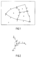
- Figure 1 shows an example of a topological network.
- This network is, for example, a network of roads as presented on a road map, a town map, a railway network, or the wiring of an electronic circuit.
- the network is a road network of a town map.
- the numerals 1, 2, ..., 6 denote intersections and the letters a, b, c, d, e, f, g and h denote a respective road section which is terminated by two intersections.
- the road section b is terminated by the intersections 2 and 3.
- a starting point and an end point is indicated for each road section.
- intersection 1 is the starting point of the road section c and the intersection 4 forms the end point.
- such intersections are denoted as 0-cells and the road sections are referred to as 1-cells.
- an n-cell represents a consecutive, n-dimensional, geometrical object.
- a surface area enclosed by road sections thus forms a 2-cell.
- four 2-cells are shown, that is to say the 2-cells A, B, C and E.
- the 2-cell A is enclosed by the 1-cells a, b, h and c and by the 0-cells 1, 2, 3 and 4.
- a network When such a network is to be stored in digital form in a memory, for example, an optical disc such as CD-ROM, in order to enable processing by means of a computer, for example in a vehicle navigation system, it is not only necessary to store the various 0-cells, 1-cells and 2-cells, but the relations between these various cells must also be known. This is because it must be possible to deduce the topology of the network from the data stored.
- a memory for example, an optical disc such as CD-ROM
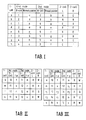
- Table I shows an example of the contents of a memory table in which the data of the topological network shown in Figure 1 is stored.
- the first column of this table contains a list of all 1-cells in alphabetical order. Each 1-cell thus forms as it were an address for a memory location.
- For each given 1-cell there is included a first 0-cell and a second 0-cell which form the starting point and the end point, respectively, of the road section associated with the relevant 1-cell.
- the 0-cells 1 and 2 are included as the first 0-cell and the second 0-cell, respectively.
- the 0-cell having the smallest X-coordinate (extreme left) is chosen as the starting point; in case of equal X-coordinates, the 0-cell having the smalles Y-coordinate is chosen as the starting point.
- a thread pointer indicates a further 1-cell which adjoins the 0-cell whereto the thread pointer has been assigned.
- the assignment of a thread pointer is realized by selecting the clockwise next-following 1-cell in a sequence of successive orientations corresponding to the subset of 1-cells terminated by the 0-cell in question. It will be evident that the direction of rotation could also be counter-clockwise and that clockwise or counter-clockwise represents a predetermined choice. For the described embodiment clockwise rotation will be chosen.
- Figure 2 shows a part of the network shown in Figure 1.
- the 1-cell b and the associated second 0-cell 3 in Figure 2 will be considered.
- the thread pointer to be assigned to the second 0-cell 3 is obtained by rotating a point P, associated with the 1-cell b and situated near the 0-cell 3, clockwise around an axis (not shown in the Figure) which extends through the 0-cell 3 and is substantially perpendicular to the plane formed by the network.
- the point P is rotated around said axis until it coincides with a point of a next 1-cell.
- the thread pointer to be assigned then indicates the 1-cell thus obtained.
- the rotation results in a point P′ which is situated on the 1-cell h and near the 0-cell 3.
- the 1-cell h is the first 1-cell obtained by rotating the point P associated with the 1-cell b in the predetermined direction.
- the thread pointer assigned to the 0-cell 3 associated with the 1-cell b thus indicates the 1-cell h.
- the result is given in table I.
- a thread pointer which indicates the 1-cell f is assigned to the 1-cell h associated with the 0-cell 3. This is because clockwise rotation of P′ results in point P ⁇ associated with the 1-cell f.
- a thread pointer is assigned to its associated first 0-cell and second 0-cell.
- the various thread pointers are shown in table I.
- the importance of defining a predetermined direction of rotation will be illustrated on the basis of the following example. For example, select the 1-cell h; the 0-cell 4 is starting intersection thereof and hence the first 0-cell, because this is the intersection having the smallest X-value.
- the thread pointer assigned to the 0-cell 4 for the 1-cell h indicates the 1-cell c when it is rotated clockwise.
- the second 0-cell associated with the 1-cell h is the 0-cell 3 and the thread pointer assigned thereto indicates the 1-cell f.
- the thread pointer assigned to the 0-cell 4 of the same 1-cell h would indicate the 1-cell g and the thread pointer assigned to the 0-cell 3 would indicate the 1-cell b. It follows therefrom that, when a different direction of rotation is chosen, obviously different thread pointers will be assigned. Thus, it is important to define the direction of rotation before drafting the memory table as given in table I in order to define an unambiguous choice of the thread pointers.
- the table I also contains the 2-cell situated to the left and the right of the relevant 1-cell.
- the 2-cell B is situated to the left of this 1-cell and the 2-cell E is situated to the right of the 1-cell d.
- the terms left and right are defined by traversing the relevant 1-cell from the starting point to the end point.
- the 2-cell B will be situated at the left and the 2-cell E will be situated at the right.
- FIG. 3 shows an example of a topological network which contains a closed loop.
- the starting point and the end point coincide in the 0-cell 12 which forms a junction 0-cell between the closed loop 3 and the 1-cell m of the network.
- TAB II the 1-cell table
- the first 0-cell (12) is the same as the second 0-cell and, moreover, the thread pointer assigned to the first 0-cell also indicates the 1-cell r.
- An alternative method for storing such a network comprising a closed loop consists in that a virtual 0-cell is included in the loop, which virtual 0-cell fictitiously subdivides the loop into two parts.
- the 1-cell r includes a virtual 0-cell 14 which subdivides the 1-cell r into two sub-1-cells r1 and r2.
- the relevant 1-cell table is the table III (TAB III).
- TAB III the table III
- the first and the second 0-cell of the 1-cell r1 are the 0-cells 12 and 14, respectively, and the 0-cells 14 and 12 are the first and the second 0-cell, respectively, of the 1-cell r2.
- the problem imposed by the same first and second 0-cells for one and the same 1-cell is thus solved.
- the consequences thereof for the searching of a 2-cell enclosed by 1-cells and 0-cells will be described hereinafter.
- a first set by taking a first 1-cell and an associated 0-cell, for example the intersection (0-cell) and the adjoining road taken by the vehicle in the case of a navigation system.
- the first set is taken as the 0-cell 3 and the 1-cell h (h, 3).
- a second set by choosing the other 0-cell associated with the first 1-cell of the first set, and also the 1-cell indicated by the thread pointer assigned to said other 0-cell.
- the 0-cell 4 is the other 0-cell (differing from the 0-cell 3) associated with the 1-cell h, and the thread pointer assigned to the 0-cell 4 indicates the 1-cell c as appears from the table I.
- the second set is formed by (c, 4).
- This second set in its turn is used to form a third set, that is to say by using the 1-cell indicated in the second set as the address for addressing the memory location in the table used for that 1-cell.
- the 0-cell other than that indicated in the second set and also the thread pointer assigned to said other 0-cell is fetched.
- said other 0-cell is formed by the 0-cell 1, because the 0-cell 4 belongs to the second set.
- a thread poiner which indicates the 1-cell a.
- the third set is now formed by (a, 1).
- the third set After the formation of the third set it is tested whether this third set does not correspond to the first set in order to determine whether the contours of the 2-cell to be found have not yet been determined. If this is not the case, the second set formed is buffered and the second set is substituted by the third set. The described operation for the second set is then repeated with the substituted second set until there is obtained a further third set which corresponds to the first set.
- the third set (a, 1) formed does not correspond to the first set (h, 3), so that the second set (c, 4) is buffered and the third set (a, 1) becomes the second set by substitution.
- the substituted second set (a, 1) there is formed a new third set (b, 2) (memory location a, 2 is the 0-cell other than 1). Because (b, 2) ⁇ (h, 3), (a, 1) is buffered.
- the buffered second sets it has thus been determined that the 2-cell is formed by the sets (h, 3), (c, 4), (a, 1) and (b, 2).
- the contours of the desired 2-cell having been found, it can simply be determined, using the information 2-cell left, 2-cell right stored in the memory table (table I), for which 2-cell the contours have been found. This is because, as has already been described, the information 2-cell left, 2-cell right is coupled to the starting point and the end point of the 1-cell for which this information is stored. Therefore, when a first set is presented, it suffices to check in the memory table whether the 0-cell included in the first set is the starting point or the end point of the 1-cell indicated in the first set. If the 0-cell included in the first set is the starting point, the 2-cell left is found because the 2-cell is contoured counter-clockwise. However, if the 0-cell included is the end point, the 2-cell right is found. In the present example (first set (h, 3)) the 0-cell 3 is the end point of the 1-cell h and, as appears from Figure 1 and table I, the 2-cell right is found, being the 2-cell A.
- the device described above can also be used for finding the other 2-cell adjoining the 1-cell of the first set. For this purpose is suffices the replace the 0-cell indicated in the first set by the other 0-cell associated with the given 1-cell and to repeat the search operation by means of the new first set thus obtained.
- the 1-cell h is then addressed.
- the 0-cell 4 is the other 0-cell associated with the 1-cell h.
- the new first set is then formed by (h, 4).
- this other 0-cell is also the 0-cell 12, because the first and the second 0-cell of the 1-cell r are identical, that is to say 0-cell 12.
- the selection of the set (r, 12) would cause an infinite circulation in the loop r, because the second set (r, 12) would continuously produced a third set (r, 12) identical to the second set. In this way the desired 2-cell, in this case the 2-cell R would never be found.
- This verification step will be described with reference to the present example (first set (k, 10)).
- the verification step produces a negative result because for the 1-cell m and 0-cells 11 and 12 are different.
- the combination (m, 12) must be chosen as the further third set, because the 1-cell m indicated by the thread poiner assigned to the second 0-cell deviates from the addressed 1-cell r.
- the further third set (s, 11) is thus found. Infinite circulation in a closed loop is thus avoided.
- the verification whether the first and the second 0-cell associated with one and the same 1-cell are the same may also be performed for searching the second set on the basis of the first set.
- a verification step may take place.
- the 2-cell to be searched is formed by a closed loop, for example the 2-cell Q enclosed by the 1-cell r ( Figure 3).
- a first set r, 12
- Formation of the second set is then no longer necessary when the 2-cell Q is searched (2-cell right), because the information follows directly from the table.
- the described search operation are very well suitable for use in a vehicle navigation system.
- the compact method of storing the network data in the memory limits the memory space required, as a result of which the read operation requires only little time. The latter is important notably when the vehicle travels at a comparatively high speed.
- an efficient method for finding a 2-cell is of essential importance for the navigation itself.
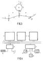
- FIG. 4 diagrammatically shows the major components of an embodiment of a vehicle navigation system.
- the vehicle navigation system comprises a bus 1 whereto there are connected a data processing unit 2, for example a microporcessor, and also a working memory 3 and a storage memory 4.
- the storage memory is formed, for example by an optical disc and an associated read member. In this storage memory there are stored map data, navigation data and other control data.
- a memory table such as the tables I, II or III is stored in the memory 4.
- a first input/output interface (5) and a second input/output interface (9) are also connected to the bus 1.
- To the first interface 5 there are connected, for example an electromagnetic compass 6, wheel sensors 7 and an odometer 8.
- the elements 6, 7, 8 serve to record data in order to enable position determination of the vehicle.
- a keyboard 10 and a reproduction element 11 are connected to the second input/output interface.
- the keyboard 10 is used inter alia for inputting the starting point and a destination for the system.
- the reproduction element 11 is formed, for example by a loudspeaker and/or a television monitor.
- the navigation system When the vehicle navigation system is in operation, coordinates which represent the position of the vehicle are determined repeatedly on the basis of the data recorded by the compass 6, the wheel sensors 7 and the odometer 8, the operation being controlled by the microprocessor 2. On the basis of these position coordinates, the navigation system must determine the 0-cell, 1-cell or 2-cell with which these position coordinates are associated.
- a method of determining to which road segment, i.e. with which 0-cell or 1-cell position coordinates are associated, is disclosed, for example in PCT application No. WO 86/00157. By using the method disclosed therein, the navigation system can thus determine a first set on the basis of the position coordinates.
- the navigation system Utilizing a device in accordance with the invention, the navigation system is also capable of establishing within which 2-cell the position coordinates are situated. This is necessary, for example when the position coordinates excessively deviate from a position on the road.
- the navigation system When the navigation system requires a 2-cell which is bounded by 0-cells and 1-cells, it will produce a first set on the basis of the position coordinates and also, if desired, a request for finding the 2-cells to the left as well as to the right of the 1-cell given in the first set.
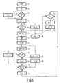
- FIG. 5 shows, in the form of a flowchart, an example of a program which is executed under the control of a data processing unit in order to find a 2-cell from the memory on the basis of a first set presented. The various steps of the flowchart will be described hereinafter.
- the 2-cell thus found can be reproduced, if desired, on the display screen of the reproduction element under the control of the microprocessor.
- the navigation system now has the 2-cell data available for realizing its navigation task.
Landscapes
- Engineering & Computer Science (AREA)
- Remote Sensing (AREA)
- Physics & Mathematics (AREA)
- General Physics & Mathematics (AREA)
- Theoretical Computer Science (AREA)
- Radar, Positioning & Navigation (AREA)
- Software Systems (AREA)
- Geometry (AREA)
- Databases & Information Systems (AREA)
- Computer Graphics (AREA)
- Data Mining & Analysis (AREA)
- General Engineering & Computer Science (AREA)
- Automation & Control Theory (AREA)
- Information Retrieval, Db Structures And Fs Structures Therefor (AREA)
- Navigation (AREA)
Claims (5)
- Vorrichtung zur Durchführung eines Suchvorgangs in einer topologischen Repräsentation eines geographischen Verbindungsnetzes, das auf Knoten (0-Zellen), je zwei der Knoten miteinander verbindenden Linienabschnitten (1-Zellen) und von diesen Linienabschnitten begrenzten singulären Gebieten (2-Zellen) beruht, wobei diese Vorrichtung einen Datenprozessor mit Vergleichsmitteln und einen diesen Linienabschnitten entsprechend adressierbaren Speicher umfaßt, dadurch gekennzeichnet, daß die Repräsentation so strukturiert ist, daß sie für jedes ursprüngliche Linienabschnittelement eine Kennzeichnung jedes ihrer Randknoten und für jeden derartigen Randknoten einen Fädelzeiger enthält, der einen bei diesem Knoten endenden und, entsprechend einem bestimmten für alle Knoten des Netzwerks gleichen Drehsinn, auf den ursprünglichen Linienabschnitt folgenden, weiteren Linienabschnitt anweist, wobei der Suchvorgang alle an ein bestimmtes Gebiet grenzenden Knoten und Linienabschnitte angibt und ausgeführt wird, indem bei einem ersten Satz begonnen wird, der einen an das genannte Gebiet grenzenden Linienabschnitt und einen diesen Linienabschnitt abschließenden ersten Knoten enthält und die aufeinanderfolgenden Sätze von Linienabschnitten und Knoten entsprechend den Fädelzeigern der den Linienabschnitt in dem vorhergehenden Satz abschließenden Knoten verkettet, bis irgendein derartiger Satz aus Linienabschnitt und Knoten beim Vergleich in den Vergleichsmitteln mit irgendeinem bei dieser Verkettung zuvor gefundenen Satz aus Linienabschnitt und Knoten identisch übereinstimmt.
- Vorrichtung nach Anspruch 1, wobei die Repräsentation bei jedem darin auftretenden Linienabschnitt, der eine geschlossene Schleife ist, einen virtuellen Knoten enthält, der mit keinem echten Knoten zusammenfällt, so daß der Datenprozessor die Schleife als zwei jeweilige Linienabschnitte behandelt.
- Vorrichtung nach Anspruch 1 oder 2, wobei jedes Linienabschnittelement eine Kennzeichnung enthält, die erste bzw. zweite Gebiete kennzeichnet, die an den zuletzt genannten Linienabschnitt grenzen, und wobei die Übereinstimmung des genannten bestimmten Gebietes mit entweder dem ersten oder dem zweiten Gebiet die Richtung der Verkettung entlang dem Linienabschnitt in dem ersten Satz bestimmt.
- In einem Fahrzeugnavigationssystem aufgenommene Vorrichtung nach einem der Ansprüche 1, 2 oder 3, das außerdem eine Positionsbestimmungseinheit enthält, um eine aktuelle Fahrzeugposition einem bestimmten der Knoten und/oder Linienabschnitte zuzuordnen.
- Vorrichtung nach einem der Ansprüche 1 bis 4, wobei der Speicher ein unabhängiges und entfernbares Speicherelement ist.
Applications Claiming Priority (2)
| Application Number | Priority Date | Filing Date | Title |
|---|---|---|---|
| NL8701738 | 1987-07-23 | ||
| NL8701738A NL8701738A (nl) | 1987-07-23 | 1987-07-23 | Werkwijze voor het opslaan van een topologisch netwerk in een geheugen en voor het opzoeken van een 2-cel uit dat netwerk, alsmede inrichting voor het uitvoeren van de werkwijze voor het opzoeken. |
Publications (3)
| Publication Number | Publication Date |
|---|---|
| EP0302547A2 EP0302547A2 (de) | 1989-02-08 |
| EP0302547A3 EP0302547A3 (en) | 1989-03-01 |
| EP0302547B1 true EP0302547B1 (de) | 1993-06-30 |
Family
ID=19850362
Family Applications (1)
| Application Number | Title | Priority Date | Filing Date |
|---|---|---|---|
| EP88201537A Expired - Lifetime EP0302547B1 (de) | 1987-07-23 | 1988-07-15 | Vorrichtung zur Durchführung eines Suchverfahrens in einer topologischen Representation eines geographischen Verbindungsnetzes. |
Country Status (7)
| Country | Link |
|---|---|
| US (1) | US4954986A (de) |
| EP (1) | EP0302547B1 (de) |
| JP (1) | JP2801208B2 (de) |
| CA (1) | CA1308493C (de) |
| DE (1) | DE3882100T2 (de) |
| ES (1) | ES2042713T3 (de) |
| NL (1) | NL8701738A (de) |
Families Citing this family (4)
| Publication number | Priority date | Publication date | Assignee | Title |
|---|---|---|---|---|
| DE69131270T2 (de) * | 1990-10-01 | 1999-12-02 | Mannesmann Vdo Ag | Verfahren zur Speicherung eines topologischen Netzwerkes und Verfahren und Geräte, um eine Reihe von 1-Zellen zu identifizieren |
| EP0479364B1 (de) * | 1990-10-01 | 1999-05-26 | Mannesmann VDO Aktiengesellschaft | Verfahren zur Speicherung eines topologischen Netzwerkes und Verfahren und Geräte, um eine Reihe von 1-Zellen zu identifizieren |
| WO1997000425A2 (en) * | 1995-06-16 | 1997-01-03 | Philips Electronics N.V. | System for joining elements to complex junctions and links in road network representation for vehicles |
| US5778243A (en) * | 1996-07-03 | 1998-07-07 | International Business Machines Corporation | Multi-threaded cell for a memory |
Family Cites Families (1)
| Publication number | Priority date | Publication date | Assignee | Title |
|---|---|---|---|---|
| US4658377A (en) * | 1984-07-26 | 1987-04-14 | Texas Instruments Incorporated | Dynamic memory array with segmented bit lines |
-
1987
- 1987-07-23 NL NL8701738A patent/NL8701738A/nl not_active Application Discontinuation
-
1988
- 1988-07-15 ES ES88201537T patent/ES2042713T3/es not_active Expired - Lifetime
- 1988-07-15 EP EP88201537A patent/EP0302547B1/de not_active Expired - Lifetime
- 1988-07-15 DE DE88201537T patent/DE3882100T2/de not_active Expired - Lifetime
- 1988-07-20 CA CA000572488A patent/CA1308493C/en not_active Expired - Lifetime
- 1988-07-22 JP JP63181972A patent/JP2801208B2/ja not_active Expired - Lifetime
- 1988-07-25 US US07/224,087 patent/US4954986A/en not_active Expired - Lifetime
Also Published As
| Publication number | Publication date |
|---|---|
| JP2801208B2 (ja) | 1998-09-21 |
| NL8701738A (nl) | 1989-02-16 |
| ES2042713T3 (es) | 1993-12-16 |
| EP0302547A2 (de) | 1989-02-08 |
| DE3882100D1 (de) | 1993-08-05 |
| DE3882100T2 (de) | 1994-01-13 |
| JPS6482259A (en) | 1989-03-28 |
| CA1308493C (en) | 1992-10-06 |
| US4954986A (en) | 1990-09-04 |
| EP0302547A3 (en) | 1989-03-01 |
Similar Documents
| Publication | Publication Date | Title |
|---|---|---|
| EP0306075B1 (de) | Fahrwegbestimmungseinheit | |
| US4758953A (en) | Method for generating logic circuit data | |
| US5038294A (en) | Automatic generating system of connection configuration diagram among units | |
| EP0280795B1 (de) | Verfahren und Einrichtung zur Speicherung einer haufenweise unterteilten Binaerdatenbasis | |
| EP1043567B1 (de) | Kartographische Datenbank | |
| CN101509783B (zh) | 应用于导航电子地图生产中的数据检查方法及装置 | |
| KR100270941B1 (ko) | 토플로지 네트워크 데이터 저장 방법 및 그 장치 | |
| JP4226491B2 (ja) | 検索データの更新システムおよびナビゲーション装置 | |
| EP0302547B1 (de) | Vorrichtung zur Durchführung eines Suchverfahrens in einer topologischen Representation eines geographischen Verbindungsnetzes. | |
| JPH08286920A (ja) | 巡回セールスマン問題処理装置 | |
| JPS6172333A (ja) | 複数ファイルのマージ方法 | |
| CN115186508B (zh) | 一种优化旅客联程运输系统的方法 | |
| JPS59108105A (ja) | 最短ル−ト検索方式 | |
| JPS59189471A (ja) | 配線経路探索システム | |
| JP3883644B2 (ja) | 引出線自動作成方法ならびにそのための引出線自動作成装置およびプログラム記憶媒体 | |
| JP3275552B2 (ja) | 車両用道路地図表示装置 | |
| JPH05108729A (ja) | 線画デ−タ検索方式および線画デ−タフオーマツト | |
| JPS6058492B2 (ja) | デ−タベ−ス検索方式 | |
| JPS63150724A (ja) | デ−タアクセス処理方式 | |
| JPH03248271A (ja) | ファイル入出力装置 | |
| JPH01181121A (ja) | 記憶領域割付け方式 | |
| JPH0667946A (ja) | 階層構造をもつデータベースにおける排他制御装置 | |
| JPS59176866A (ja) | プリント板の自動配線方法 | |
| JPH04250558A (ja) | 経路計画方法とその装置 | |
| JPH0652238A (ja) | ディジタル道路地図検索装置 |
Legal Events
| Date | Code | Title | Description |
|---|---|---|---|
| PUAI | Public reference made under article 153(3) epc to a published international application that has entered the european phase |
Free format text: ORIGINAL CODE: 0009012 |
|
| PUAL | Search report despatched |
Free format text: ORIGINAL CODE: 0009013 |
|
| AK | Designated contracting states |
Kind code of ref document: A2 Designated state(s): CH DE ES FR GB IT LI SE |
|
| AK | Designated contracting states |
Kind code of ref document: A3 Designated state(s): CH DE ES FR GB IT LI SE |
|
| 17P | Request for examination filed |
Effective date: 19890831 |
|
| 17Q | First examination report despatched |
Effective date: 19910909 |
|
| GRAA | (expected) grant |
Free format text: ORIGINAL CODE: 0009210 |
|
| AK | Designated contracting states |
Kind code of ref document: B1 Designated state(s): CH DE ES FR GB IT LI SE |
|
| REF | Corresponds to: |
Ref document number: 3882100 Country of ref document: DE Date of ref document: 19930805 |
|
| ITF | It: translation for a ep patent filed | ||
| ET | Fr: translation filed | ||
| PLBE | No opposition filed within time limit |
Free format text: ORIGINAL CODE: 0009261 |
|
| STAA | Information on the status of an ep patent application or granted ep patent |
Free format text: STATUS: NO OPPOSITION FILED WITHIN TIME LIMIT |
|
| 26N | No opposition filed | ||
| EAL | Se: european patent in force in sweden |
Ref document number: 88201537.3 |
|
| ITPR | It: changes in ownership of a european patent |
Owner name: CAMBIO RAGIONE SOCIALE;PHILIPS ELECTRONICS N.V. |
|
| REG | Reference to a national code |
Ref country code: CH Ref legal event code: PFA Free format text: PHILIPS ELECTRONICS N.V. |
|
| REG | Reference to a national code |
Ref country code: FR Ref legal event code: CD |
|
| REG | Reference to a national code |
Ref country code: ES Ref legal event code: PC2A Owner name: PHILIPS ELECTRONICS N.V. |
|
| PGFP | Annual fee paid to national office [announced via postgrant information from national office to epo] |
Ref country code: CH Payment date: 19971017 Year of fee payment: 10 |
|
| REG | Reference to a national code |
Ref country code: CH Ref legal event code: PFA Free format text: PHILIPS ELECTRONICS N.V. TRANSFER- KONINKLIJKE PHILIPS ELECTRONICS N.V. |
|
| PG25 | Lapsed in a contracting state [announced via postgrant information from national office to epo] |
Ref country code: LI Free format text: LAPSE BECAUSE OF THE APPLICANT RENOUNCES Effective date: 19980731 Ref country code: CH Free format text: LAPSE BECAUSE OF THE APPLICANT RENOUNCES Effective date: 19980731 |
|
| REG | Reference to a national code |
Ref country code: CH Ref legal event code: PUE Owner name: KONINKLIJKE PHILIPS ELECTRONICS N.V. TRANSFER- MAN |
|
| REG | Reference to a national code |
Ref country code: GB Ref legal event code: 732E |
|
| REG | Reference to a national code |
Ref country code: FR Ref legal event code: TP |
|
| REG | Reference to a national code |
Ref country code: CH Ref legal event code: PL |
|
| REG | Reference to a national code |
Ref country code: ES Ref legal event code: PC2A |
|
| REG | Reference to a national code |
Ref country code: GB Ref legal event code: IF02 |
|
| PGFP | Annual fee paid to national office [announced via postgrant information from national office to epo] |
Ref country code: ES Payment date: 20020715 Year of fee payment: 15 |
|
| PGFP | Annual fee paid to national office [announced via postgrant information from national office to epo] |
Ref country code: SE Payment date: 20020724 Year of fee payment: 15 |
|
| PG25 | Lapsed in a contracting state [announced via postgrant information from national office to epo] |
Ref country code: SE Free format text: LAPSE BECAUSE OF NON-PAYMENT OF DUE FEES Effective date: 20030716 Ref country code: ES Free format text: LAPSE BECAUSE OF NON-PAYMENT OF DUE FEES Effective date: 20030716 |
|
| EUG | Se: european patent has lapsed | ||
| REG | Reference to a national code |
Ref country code: ES Ref legal event code: FD2A Effective date: 20030716 |
|
| PGFP | Annual fee paid to national office [announced via postgrant information from national office to epo] |
Ref country code: DE Payment date: 20070919 Year of fee payment: 20 |
|
| PGFP | Annual fee paid to national office [announced via postgrant information from national office to epo] |
Ref country code: GB Payment date: 20070710 Year of fee payment: 20 |
|
| PGFP | Annual fee paid to national office [announced via postgrant information from national office to epo] |
Ref country code: IT Payment date: 20070726 Year of fee payment: 20 |
|
| PGFP | Annual fee paid to national office [announced via postgrant information from national office to epo] |
Ref country code: FR Payment date: 20070720 Year of fee payment: 20 |
|
| REG | Reference to a national code |
Ref country code: GB Ref legal event code: PE20 Expiry date: 20080714 |
|
| PG25 | Lapsed in a contracting state [announced via postgrant information from national office to epo] |
Ref country code: GB Free format text: LAPSE BECAUSE OF EXPIRATION OF PROTECTION Effective date: 20080714 |