EP0302542A1 - Dispositif pour transporter des supports à partir et en direction d'un dispositif de positionnement et dispositif sélecteur destiné à un dispositif - Google Patents
Dispositif pour transporter des supports à partir et en direction d'un dispositif de positionnement et dispositif sélecteur destiné à un dispositif Download PDFInfo
- Publication number
- EP0302542A1 EP0302542A1 EP88201463A EP88201463A EP0302542A1 EP 0302542 A1 EP0302542 A1 EP 0302542A1 EP 88201463 A EP88201463 A EP 88201463A EP 88201463 A EP88201463 A EP 88201463A EP 0302542 A1 EP0302542 A1 EP 0302542A1
- Authority
- EP
- European Patent Office
- Prior art keywords
- displaceable
- selection device
- carrier
- slide
- coupled
- Prior art date
- Legal status (The legal status is an assumption and is not a legal conclusion. Google has not performed a legal analysis and makes no representation as to the accuracy of the status listed.)
- Granted
Links
Images


Classifications
-
- H—ELECTRICITY
- H05—ELECTRIC TECHNIQUES NOT OTHERWISE PROVIDED FOR
- H05K—PRINTED CIRCUITS; CASINGS OR CONSTRUCTIONAL DETAILS OF ELECTRIC APPARATUS; MANUFACTURE OF ASSEMBLAGES OF ELECTRICAL COMPONENTS
- H05K13/00—Apparatus or processes specially adapted for manufacturing or adjusting assemblages of electric components
- H05K13/0061—Tools for holding the circuit boards during processing; handling transport of printed circuit boards
-
- H—ELECTRICITY
- H05—ELECTRIC TECHNIQUES NOT OTHERWISE PROVIDED FOR
- H05K—PRINTED CIRCUITS; CASINGS OR CONSTRUCTIONAL DETAILS OF ELECTRIC APPARATUS; MANUFACTURE OF ASSEMBLAGES OF ELECTRICAL COMPONENTS
- H05K13/00—Apparatus or processes specially adapted for manufacturing or adjusting assemblages of electric components
- H05K13/08—Monitoring manufacture of assemblages
- H05K13/086—Supply management, e.g. supply of components or of substrates
Definitions
- the invention relates to an apparatus for the transport of carriers from and to a positioning device.
- the invention also relates to a selection device for use in such an apparatus.
- the invention has for its object to provide an apparatus for the transport of carriers from and to a positioning device, in which the disadvantages described are avoided.
- the apparatus according to the invention is for this purpose characterized in that magazine containing carriers grouped vertically can be coupled to a selection device which is displaceable vertically along a magazine and is provided with a gripper mechanism, which is displaceable horizontally and can be coupled to carriers displaceable horizontally between the magazine and the selection device: in a delivery operation of the selection device a gripper mechanism being coupled at a first relative vertical level between the selection device and the positioning device to a carrier in the selection device and being displaced together with the carrier horizontally to the positioning device; and in a fetching operation of the selection device a gripper mechanism being coupled at a second relative vertical level between the selection device and the positioning device to a carrier at the location of the positioning device and being displaced together with the carrier horizontally from the positioning device to the selection device.
- the carrier may be designed for the transport of components, of products, of tools or of combinations thereof.
- a product may also be a so-called intermediate product, which
- a particular embodiment of the apparatus according to the invention is further characterized in that the selection device comprises a first and a second gripper mechanism arranged in a frame, which is provided at a first vertical level with a first pair of parallel guides for a carrier associated with the first gripper mechanism and is provided at a second vertical level with a second pair of parallel guides for a carrier associated with the second gripper mechanism.
- a further embodiment of an apparatus according to the invention having a selection device of comparatively low mass is characterized in that the selection device, displaceable vertically between a magazine and a positioning device, comprises a single gripper mechanism by means of which in the delivery operation carriers are displaceable horizontally onto a table in the positioning device at a first vertical level and by means of the table are displaceable vertically to a second vertical level in the positioning device, at which a pair of parallel guides are situated for supporting and horizontally transporting the carrier in the fetch operation.
- a still further embodiment of an apparatus according to the invention having a comparatively simple compact and robust gripper mechanism, in which the movement of the gripper or end effecter follows a straight-line and takes place uniformly without jolts, is characterized in that the gripper mechanism comprises two arms, which are displaceable in horizontal planes at right angles to a vertical main axis and of which a driving arm is rotatable about the main axis, while a supporting arm pivotably connected to the driving arm is rotatable about a pivot axis parallel to the main axis, an end effector coupled to the supporting arm near the end of the supporting arm remote from the driving arm being displaceable along a straight line which perpendicularly intersects the main axis.
- a further embodiment of an apparatus according to the invention in which the straight line guiding of the gripper mechanism is obtained in a comparatively simple manner, is characterized in that the drive of the driving arm supported by the slide has a first gear wheel which is secured on the slide, is co-axial with the main axis, and which meshes with a second gear wheel which is rotably arranged on the driving arm so as to roll over the first gear wheel and which meshes with a third gear wheel which is secured on the supporting arm and is co-axial with the said pivot axis, the pitch circle diameters of the first, second and third gear wheels having a ratio of 2 : 1 : 1, while the lengths of the driving arm and the supporting arm have a ratio of 1 : 1.
- a still further embodiment of an apparatus according to the invention, having a clearance-free drive for the driving arm of the gripper mechanism is characterized in that the slide constitutes a guide for a carriage which is displaceable with respect thereto parallel to the said line and is coupled by means of two flexible strips to a disc, which is secured to the driving arm and is rotatable together with the driving arm about the main axis.
- a still further embodiment of an apparatus according to the invention having a comparatively light and inexpensive drive of the carriage is characterized in that the carriage is coupled to a first pneumatic motor secured on the slide, while the carriage is displaceable against spring force with respect to the slide.
- the first kind of automated assembly line illustrativelyed in Fig. 1 has a so-called decentral supply of compo nents, which will be explained more fully hereinafter.
- the assembly line designated by reference numeral 1 is composed of two parallel tracks 3 and 5, which are coupled near a beginning point and an end point with each other by means of a first transfer means and a second transfer means 9. 0n the tracks 3 and 5 are arranged a number of plate-shaped product carriers 11, which follow a path on the assembly line 1 as indicated by arrows 13.
- the product carriers 11 are driven in the horizontal tracks 3 and 5 by friction rollers 15, which are coupled by means of strings 17 with parallel horizontal driving shafts 19 and 21 extending throughout the length of the tracks.
- the transfer means 7 and 9 include friction rollers 23, which are driven in the same manner as the friction rollers 15.
- the component supply takes place from a central store 25, containing horizontally displaceable magazines 27 containing plate-shaped component carriers 29, grouped vertically.
- the central store 25 further contains magazines 31, which are horizontally displaceable and are filled with the product carriers 11 grouped vertically.
- the magazines 27 and 31 in the present case have the same construction, although this is not necessary.
- the plate-shaped component carriers 29 and the plate-shaped product carriers 11 have the same outer dimensions and can be arranged both in the magazines 27 and in the magazines 31, although this is not the case here.
- a product on a product carrier 11 may be, for example, a chassis, in which the components from a component carrier 29 have to be mounted at a so-called work station. With a decentral supply of components, these components are supplied at a work station to the assembly line 1 by means of the component carriers 29, while the supply of the product carriers 11 takes place elsewhere along the assembly line 1. In the assembly line shown in Fig. 1 with working stations A, B and C the supply and the discharge of full and empty component carriers 29 take place decentrally in the working stations B and C. The supply and the discharge respectively of untreated and treated product carriers 11 take place at a station D.
- Assembly robots R(A), R(B) and R(C) are situated at the work stations A, B and C, respectively, and are of a kind as shown on an enlarged scale in Figures 3 and 4. It can be seen from Figures 3 and 4 that the robots R(A), R(B) and R(C), in a given horizontal plane, have a rectangular working space, which con be arranged to cover optimally the required assembly area of the assembly line 1.
- a centering device (not shown) of a conventional type, which provides correct positioning of the component carriers relative to the robots by means of pins and centering holes in the component carriers 23.
- the centering devices (not shown) and the robots have to be considered as a positioning device of the kind already stated in the preamble.
- the centered position of the component carrier 29 is a waiting position, from which the robot can transport components from this local store to a product carrier 11 situated on the track 3 of the assembly line 1.
- a selection device 33 Between the magazines 27 containing components at the work stations B and C and the assembly line there is arranged a selection device 33. There is also a selection device 33 between the magazine 31 containing products and the assembly line 1 at the work station D.
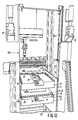
- the magazines 27 and 31 can be detachably secured to the selection devices 33 by means of a pneumato-mechanical coupling 35, of which a part situated on the magazines is shown in Fig. 1 and a part situated on the selection device is shown in Fig. 12.
- product carriers 11 and component carriers 29 can be transferred from a magazine 31 to the assembly line 1 (track 3) and from a magazine 27 to a centered position at one or more of the work stations A, B and C, respectively.
- the movements of a component carrier or product carrier associated with such a transfer will be discussed with reference to the diagrammatic Figures 5 and 6 before the construction of the selection device 33 is described.
- Fig. 5 shows the movements of a first kind of selection device 33a comprising first and second gripper mechanisms G1 and G2 arranged in a frame 37
- Fig. 6 shows the movements of a second kind of selection device 33b comprising only a single gripper mechanism G arranged in a frame 37
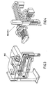
- the gripper mechanism G, G1, G2 of the two kinds of selection devices 33a and 33b have the same construction, which is shown with reference number 39 in Figures 7, 8 and 9.
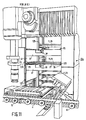
- Figures 11 and 12 show a selection device of the first kind comprising two gripper mechanisms.
- the two frames 37 each with a gripper mechanism 39 are secured to a slide 41, which is arranged to provide vertical displacement under control of a program (cf. Fig. 11).
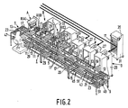
- Fig. 2 serves to illustrate the flexibility of the apparatus according to the invention and is therefore also provided as far as possible with reference numerals corresponding to Fig. 1.
- the assembly line 1 shown in Fig. 2 the supply and discharge of the component carriers 29 take place at two stations E and F and not at the work stations A, B or C.
- the supply and the discharge of the product carriers 11 take place in the station D.
- Such a supply and such a discharge of component carriers and product carriers not taking place in the working stations A, B or C are designated as central supply and central discharge respectively.
- the assembly line 1 is now provided with two levels i.e. an upper level with the tracks 3,5 and the transfer means 7,9, at which product carriers 11 follow the trajectory 13, and a lower level with tracks 43,45 and transfer means 47, 49 at which component carriers 29 follow a trajectory 51.
- the component carriers 29 are driven in the same manner as described already hereinbefore with reference to Fig. 1.
- the selection devices 33 in the working stations B and C serve in the first place as an elevator between the two levels of the assembly line.
- the selection devices 33 in the stations E and F always operate to two sides: on the side of the magazines 27 with component carriers 29 a choice is made from the levels of the magazines while on the side of the assembly line 1 component carriers 29 are constantly supplied to or discharged from the lower level of the assembly line 1.
- component carriers 29 are not transferred horizontally via the selection devices 33 of the work stations B or C to some store, although the system would be suitable for this purpose.
- the assembly line having a decentral supply of components at the work stations A, B or C has a comparatively low load of the transport system, a comparatively simple process control and a comparatively small capital investment.
- the assembly line having a central supply of components in a fixed (central position relative to the assembly line which is not located in the work stations A, B or C exhibits a comparatively clear and unambiguous transport from the central store to the assembly line, a comparatively small speed of material over the assembly line so that supervision thereof is simple and a comparatively high flexibility (freedom of choice) in the case of modification of the assembly pattern ( inter alia order of assembly operations in the working stations).
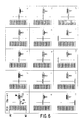
- a delivery operation and a fetching operation for a component or product carrier 29,11 is described more fully by means of eleven enumerated processing steps (pictures 5.1 to 5.11).
- the operations start in picture 5.1, in which the situation is shown in which the gripper G2 has just transported a full carrier (end) of delivery operation to the centering device (positioning device).
- picture 5.2 shows a centering of the carrier, as a result of which the latter reaches a working level W.
- picture 5.3 the assembly operations are started and the frame 37 descends to a level M2 in the magazine 27,31.
- the gripper G1 is now located at the level M2 and in picture 5.4 places an empty carrier in the magazine.
- picture 5.5 the frame 37 then ascends to the level M1 in the magazine and in picture 5.6 the lower gripper G2 fetches a full carrier to the frame 37.
- the picture 5.7 indicates that the frame 37 has descended to just below the working level and is in a waiting position until the carrier in the positioning device is empty and the assembly operations have terminated.
- the carrier is emptied by the robot, while in picture 5.9 the empty carrier is decentered in the positioning device.
- picture 5.10 the upper gripper G1 has transported the empty carrier from the positioning device to the frame 37.
- picture 5.11 the frame 37 has ascended to slightly below the working level W so that the lower gripper G2 can bring a full carrier to the positioning device and a new starting position is reached.
- a delivery operation and a fetching operation for a component or product carrier 29,11 are described by means of fifteen enumerated processing steps (pictures 6.1 to 6.15).
- the operations start in picture 6.1, in which the situation is shown in which a gripper G has just transported a full carrier from the selection device 33b to a pneumatically vertically displaceable table 53.
- the table 53 can be provided with a full carrier below the working level W at which a decentered carrier is arranged and operated on by a robot at the assembly line 1.
- the selection device 33b ascends to just below the working level W and is at that level in a waiting position until the upper carrier is emptied by the robot at the level W. This situation is reached in picture 6.3.
- the upper carrier is decentered. After the upper empty carrier has been gripped by the gripper G, the gripper G transports the empty carrier to the selection device 33b, as indicated in picture 6.5.
- two parallel straight line guides for a carrier which can be moved horizontally away from each other and towards each other, are located just below the working level W. Such a parallel displacement of guides may be obtained, for example, by means of a rod mechanism or eccentric mechanism, which is driven by a pneumatically controlled piston.
- a comparison of the selection devices 33a and 33b shown in Figures 5 and 6 clearly shows that one of the afore mentioned two relative vertical levels represents a local supply level with an associated waiting position located for the selection device 33a in the selection device itself and for the selection device 33b below the working level W at the area of the positioning device (centering device, robot).
- the delivery operation of the selection device 33a shown in Fig. 5 relates to the pictures 5.11 and 5.1, while the fetching operation relates to the pictures 5.9 and 5.10.
- the delivery operation relates to pictures 6.15 and 6.1, while the fetching operation stage relates to the pictures 6.4 and 6.5.
- fetching operation and “delivery operation” only relate to the interactions between the selection device and the positioning device and do not relate to the steps of delivering empty carriers to the magazine and of fetching full carriers from the magazine.
- the relative vertical transport levels between the selection device and the positioning device and not the relative position of the selection device and the magazine are inter alia characteristic of the invention.
- the gripper mechanism 39 shown in Figures 7, 8 and 9 comprises a driving arm 57 which is rotatable about a main axis 55 and is pivotably connected to a supporting arm 59 at the area of a pivot axis 61 near its end remote from the main axis 55.
- the main axis 55 and the pivot axis 61 are parallel to each other.
- the supporting arm 59 is provided with an end effector or gripper 63, which can be displaced along a straight horizontal line perpendicularly intersecting the main axis 55. It should be noted that from Fig. 7 to Fig. 9 the situation is shown in increasingly greater detail. Particulars about the drive of the arms 57 and 59 are not visible in Fig.
- the main axis 55 is constituted by the centre line of a stub shaft 67, which is connected to a slide 65 and on which the driving arm 57 is rotatably journalled (cf. Fig. 9).
- a gear wheel segment 69 secured to the slide 65 is integrated with the stub shaft 67.
- a gear wheel 71, which meshes with the gear wheel segment 69, and is rotatable about an axis parallel to the main axis 55, is journalled in the driving arm 57.
- a gear wheel 73 which meshes with the gear wheel 71 and is rotatable about the pivot axis 61, is secured to the supporting arm 59 (cf. Fig 8).
- the gear wheel 71 Upon rotation of the driving arm 57 about the main axis 55, the gear wheel 71 consequently rolls over the gear wheel segment 69 and the gear wheel 73 rotates together with the supporting arm 59 about the pivot axis 61.
- the diameters of the so-called pitch circles of the gear wheel segment 69, of the gear wheel 71 and of the gear wheel 73 have a ratio of 2 : 1 : 1 and the lengths of the driving arm 57 and of the supporting arm 59 have a ratio of 1 : 1.
- the length of the driving arm 57 is to be understood to mean the shortest distance between the main axis 55 and the pivot axis 61
- the length of the supporting arm 59 is to be understood to mean the distance between the pivot axis 61 and a line parallel thereto through the point of engagement of the gripper 63 with a carrier 11,29.
- the gripper 63 has a U-shaped cross-section with limbs 75, which hook behind edges 77 (cf. Figures 11 and 12) of carriers 11,29. Due to the said diameter and length ratios, it is achieved that the gripper 63 follows a straight line perpendicularly intersecting the main axis 55 and extending parallel to a pair of guides 79 on the frame 37.
- the upper frame 37 has a first pair of parallel guides 79 and the lower frame 37 has a second pair of parallel guides 79.
- the selection device 33b comprises only one frame 37 secured to the slide 41 and having one pair of guides 79.
- the frame 37 is provided with two passages 81 for the gripper 63.
- the rotation of the driving arm 57 is obtained as follows (cf. Fig. 9).
- the end of the driving arm 57 located near the main axis 55 is in the form of a circular disc 83, onto which a first flexible metal strip 85 and a second flexible metal strip 87 can be wound.
- the first strip 85 is secured at one end to the disc 83 at a point designated by reference numeral 89 and at its other end to a carriage 91 displaceable over the slide 65.
- the second strip 87 is secured at one end to the disc 83 at a point designated by reference numeral 93 and at its other end to the carriage 91.
- the carriage 91 is displaceable along a straight line guide 95, which is secured on the slide 65 and is parallel to the line along which the gripper 63 is displaced.
- a known first pneumatic motor 97 (cf. Fig.
- the slide 65 is coupled to a known second pneumatic motor 99, of which a piston rod 101 is secured to the frame 37 and of which a cylinder 103 is secured to the slide 65.
- the slide 65 is also displaceable along a guide 105 (cf. Figures 8 and 9) parallel to the straight line which is followed by the gripper 63.
- the carriage 91 is provided with a flange 107, which serves as a support and which is engaged on one side by a helical spring 109 and on the other side by a helical spring 111.
- the helical springs 109 and 111 are arranged to surround a circular rod 113, which passes through the flange 107 and is supported in two bearing blocks 115 and 117 which are secured on the slide 65 (cf. Fig. 8). Supports 119 and 121 for the springs 109 and 111 are secured on the rod 113.
- Only the spring 111 is in under stress; the spring 109 is not loaded.
- the springs 109 and 111 onsequently are either not loaded or are subjected to compressive stress and are therefore used as compression springs.
- Such collision forces would be caused by the first pneumatic notor 97 (cf. Fig. 7), which supplies a sub stantially constant driving force over the whole trajectory over which the carriage 91 is displaced.
- a lift arm 123 is provided in the supporting arm 59.
- the gripper 63 is secured on the lift arm 123 so as to be rotatable about an axis parallel to the main axis 55.
- the lift arm 123 is pivotable (not shown) in the supporting arm 59 and is for this purpose driven pneumatically in known manner by a tiltable piston red, which is secured to the supporting arm 59, and a tiltable cylinder, which is secured to the lift arm.
- the operation of the gripper mechanism will now be described more fully also with reference to the diagrammatic Fig. 10.
- the gripper 63 is situated in the position indicated in Figures 5.5 and 6.13, in which a carrier 11,29 is removed from the magazine 31,27.
- the lefthand limb 75 of the gripper 63 is then hooked in the upper position of the lift arm 123 behind the righthand edge 77 of the carrier 11,29. Since the lengths of the driving arm and the supporting arm 59/lift arm 123 are equal to R, the lefthand limb 75 of the gripper 63 is located at a distance 2R plus half the gripper width from the main axis 55.
- the width of the gripper is neglected hereinafter for the sake of simplicity.
- the carrier 11,29 has a width X satisfying the condition X > 2R.
- the slide 65 is located in the extreme lefthand position within the frame 37. This position corresponds to the situation shown in Fig. 5.5 and Fig. 6.13, in which the selection device 33a and 33b, respectively, is ready to remove a full carrier 11,29 from the magazine 31,27, and to the situation shown in Figures 1, 2, 11 and 12, in which a carrier 11,29 present in the positioning device must be fetched (just after decentering).
- the gripper 63 By a rotation of the driving arm 57 about the main axis through an angle of + ⁇ radians, in which event the gripper 63, following a straight line, pulls the carrier 11,29 into the guides 79 of the frame 37 of L-shaped cross-section, the gripper mechanism is moved into the position indicated in Fig.
- the carrier is now displaced to the right by means of rollers 125 in the guides 79 over a distance 4R, passing through the position of the gripper mechanism indicated in Fig. 8.
- the gripper 63 is now detached from the righthand edge 77 of the carrier 11,29 by lowering the lift arm 123 in the supporting arm 59.
- the slide 65 is displaced to the right by means of the second pneumatic motor 99 over a distance 4R-X so that the main axis 55 occupies the position indicated by reference numeral 55a.
- the driving arm 57 is rotated through an angle of - ⁇ radians about the main axis 55 and the lift arm 123 with the gripper 63 is raised again.
- the lefthand edge 77 of the carrier 11,29 is gripped as indicated in Fig. 10.3.
- the driving arm 57 is again rotated through an angle of + ⁇ radians about the main axis 55.
- the overall horizontal displacement of the carrier 11,23 is now 8R and suffices for a transport from the magazine 27,31 through the selection devices 33a, 33b to the positioning device, or conversely.
- the distance 8R is covered in stages and generally not at the same vertical level. After a distance 4R has been covered, the carrier is situated in the selection device, which then chooses the desired level by raising or lowering the frame 37. It is not until then that a next distance 4R is covered in horizontal direction.
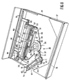
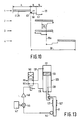
- the steps of raising and lowering the frame 37 in the selection devices 33a, 33b are described with reference to Figures 11 and 12 and the diagrammatic drive shown in Fig. 13.
- the Figures 11 and 12 relate to a selection device 33a having two frames 37 and two gripper mechanisms 39.
- the drive of a selection device 33b having only one gripper mechanism 39 in one frame 37 is the same as the drive of the selection device 33a.
- the selection device 33a is provided with a number of parallel guides 127, which extend vertically and in which the slide 41 is guided.
- the slide 41 is displaced by means of a third pneumatic motor 129 (cf. Fig. 13), of which a piston 133 displaceable in a cylinder 131 is coupled by means of a piston rod 135 to the slide.
- a third pneumatic motor 129 cf. Fig. 13
- a piston 133 displaceable in a cylinder 131 is coupled by means of a piston rod 135 to the slide.
- the cylinder 131 is connected by means of pipes 137 and 139, respectively, to an electro-pneumatic 4/2 valve 141 having a pressure port PR and an exhaust port RE.
- the displacement of the slide is measured by means of a mechano-electrical converter 143, of which the output signal is supplied to a comparator 145.
- a signal corresponding to the desired position of the slide 41 is supplied to the comparator 145 and is compared therein with the output signal of the converter 143.
- the comparator gene severelyrates a difference signal, which after amplification in an amplifier 149 is used for energization of the coil of the electro-pneumatic valve 141.
- the slide 41 can be brought into any desired vertical position and held in this position.
- the slide 41 may be provided with a lock which is activated when the desired position is reached. When the slide 41 is held mechanically via a lock in the guides 127 in the desired position, a stable positioning is attained without a continuous pneumatic control being necessary.
- Such a lock may be controlled pneumatically, electro-pneumatically or electro-magnetically and is of a conventional type.
- an assembly and/or a production system is obtained which is very flexible in such a way that an optimum freedom of choice is available with regard to the kind of components and products as well as with regard to the order in which the various operations can be carried out.
- This is also due to the fact that the system has a highly modular construction.
- the pneumatic drives or motors described may be replaced by electrical or hydraulic drives.
- the selection device may be used essentially at an unlimited number of vertical and horizontal levels and may be combined with many kinds of transport tracks, although the combination with the variable transport system described has inter alia particular advantages with regard to flexibility, production modifications, system enlargement, etc.
Applications Claiming Priority (2)
| Application Number | Priority Date | Filing Date | Title |
|---|---|---|---|
| NL8701649 | 1987-07-14 | ||
| NL8701649 | 1987-07-14 |
Publications (2)
| Publication Number | Publication Date |
|---|---|
| EP0302542A1 true EP0302542A1 (fr) | 1989-02-08 |
| EP0302542B1 EP0302542B1 (fr) | 1994-01-26 |
Family
ID=19850304
Family Applications (1)
| Application Number | Title | Priority Date | Filing Date |
|---|---|---|---|
| EP88201463A Expired - Lifetime EP0302542B1 (fr) | 1987-07-14 | 1988-07-11 | Dispositif pour transporter des supports à partir et en direction d'un dispositif de positionnement et dispositif sélecteur destiné à un dispositif |
Country Status (5)
| Country | Link |
|---|---|
| US (1) | US5085553A (fr) |
| EP (1) | EP0302542B1 (fr) |
| JP (1) | JPS6434617A (fr) |
| CA (1) | CA1317897C (fr) |
| DE (1) | DE3887405T2 (fr) |
Cited By (16)
| Publication number | Priority date | Publication date | Assignee | Title |
|---|---|---|---|---|
| EP0472155A1 (fr) * | 1990-08-21 | 1992-02-26 | Fujitsu Limited | Equipement d'usinage pour produits variés |
| US5094584A (en) * | 1989-04-06 | 1992-03-10 | Hewlett-Packard Company | Method and apparatus for automatically changing printed circuit board test fixtures |
| US5104277A (en) * | 1989-04-06 | 1992-04-14 | Hewlett-Packard Company | Method and apparatus for automatically changing printed circuit board test fixtures |
| EP0593367A1 (fr) * | 1992-10-16 | 1994-04-20 | Commissariat A L'energie Atomique | Système de stockage et de transport d'objets plats tels que des boîtes extra-plates et son ratelier portatif |
| US5358375A (en) * | 1991-04-11 | 1994-10-25 | Amada Company, Limited | Device for transferring materials and product with respect to a processing machine |
| EP0684758A2 (fr) * | 1994-05-24 | 1995-11-29 | Tenryu Technics Co., Ltd. | Dispositif pour le transport et le montage de pièces électroniques |
| NL1013569C2 (nl) * | 1999-11-12 | 2001-05-15 | Fico Bv | Transportinrichting en werkwijze voor het verplaatsen van productdragers voor elektronische componenten. |
| WO2001045482A1 (fr) * | 1999-12-16 | 2001-06-21 | Siemens Aktiengesellschaft | Dispositif de mise en place de composants comprenant plusieurs lignes de transport pour les substrats devant recevoir les composants |
| WO2002013589A1 (fr) * | 2000-08-10 | 2002-02-14 | Siemens Aktiengesellschaft | Procede permettant de faire fonctionner une installation d'implantation de composants, installation d'implantation de composants permettant la mise en oeuvre du procede, et dispositif de transfert destine a l'installation d'implantation de composants |
| WO2002094691A2 (fr) * | 2001-05-23 | 2002-11-28 | Siemens Aktiengesellschaft | Dispositif de manipulation conçu pour deplacer des objets |
| WO2002095793A2 (fr) * | 2001-05-23 | 2002-11-28 | Siemens Aktiengesellschaft | Systeme et procede pour equiper des substrat avec des composants |
| WO2007023078A1 (fr) * | 2005-08-25 | 2007-03-01 | Robert Bosch Gmbh | Dispositif pour recevoir et manipuler mecaniquement des pieces a transporter |
| EP1928221A2 (fr) * | 2006-11-29 | 2008-06-04 | ESSEGI SYSTEM SERVICE S.r.l. | Dispositif accumulateur pour composants électroniques |
| EP1962571A2 (fr) * | 2007-02-22 | 2008-08-27 | Siemens Aktiengesellschaft | Dispositif et procédé de préparation de magasins de surface, système d'implantation |
| CN102374945A (zh) * | 2011-10-10 | 2012-03-14 | 常州市中威电子仪器有限公司 | 生物组织染色机 |
| WO2016103154A1 (fr) | 2014-12-22 | 2016-06-30 | Essegi System Service S.R.L. | Unité de stockage améliorée |
Families Citing this family (18)
| Publication number | Priority date | Publication date | Assignee | Title |
|---|---|---|---|---|
| US5257897A (en) * | 1990-06-05 | 1993-11-02 | Murata Kikai Kabushiki Kaisha | Can conveying system |
| US5222856A (en) * | 1990-06-05 | 1993-06-29 | Murata Kikai Kabushiki Kaisha | Can conveying system |
| DE4103479C2 (de) * | 1991-02-06 | 1995-04-20 | Tetra Pak Gmbh | Vorrichtung zum Verstellen des Aufnahmevolumens eines Gutträgers |
| US5181820A (en) * | 1991-03-27 | 1993-01-26 | Quipp Systems, Inc. | Automatic bundle loading apparatus and method |
| US5474410A (en) * | 1993-03-14 | 1995-12-12 | Tel-Varian Limited | Multi-chamber system provided with carrier units |
| JP2762928B2 (ja) * | 1994-05-17 | 1998-06-11 | 村田機械株式会社 | 物品移載装置 |
| US5498117A (en) * | 1994-08-29 | 1996-03-12 | Tachi-S Co., Ltd. | Device for sidetracking a truck |
| CA2208385A1 (fr) * | 1996-06-21 | 1997-12-21 | Cannon Equipment Company | Chargeur de chariots et methode de chargement |
| JP3491557B2 (ja) * | 1999-04-22 | 2004-01-26 | 松下電器産業株式会社 | 電子部品供給用のトレイフィーダ |
| US8915692B2 (en) * | 2008-02-21 | 2014-12-23 | Harvest Automation, Inc. | Adaptable container handling system |
| ITBO20080140A1 (it) | 2008-03-03 | 2009-09-04 | Biesse Spa | Metodo e macchina per la lavorazione di componenti di legno o simili |
| DE102010001724B4 (de) * | 2010-02-09 | 2012-02-02 | Miksch Gmbh | Regalmagazin |
| DE102011076595A1 (de) * | 2011-05-27 | 2012-11-29 | Homag Holzbearbeitungssysteme Gmbh | Bearbeitungsvorrichtung |
| US9147173B2 (en) | 2011-10-31 | 2015-09-29 | Harvest Automation, Inc. | Methods and systems for automated transportation of items between variable endpoints |
| US8937410B2 (en) | 2012-01-17 | 2015-01-20 | Harvest Automation, Inc. | Emergency stop method and system for autonomous mobile robots |
| US9351569B1 (en) * | 2013-02-11 | 2016-05-31 | Automated Cells and Equipment, Inc. | Parts supply drawer system for robot assisted manufacturing |
| CN107226314A (zh) * | 2016-03-25 | 2017-10-03 | 佳宸科技有限公司 | 高效率储物系统 |
| FR3076546B1 (fr) * | 2018-01-10 | 2020-05-08 | Colib | Systeme d'entreposage et distribution de marchandises |
Citations (4)
| Publication number | Priority date | Publication date | Assignee | Title |
|---|---|---|---|---|
| FR2008956A1 (fr) * | 1968-05-20 | 1970-01-30 | Seveco Sa | |
| GB1202361A (en) * | 1966-05-12 | 1970-08-19 | David Theodore Nelson Williams | Improvements in or relating to a programme-controlled machine tool installation |
| EP0076238A2 (fr) * | 1981-09-28 | 1983-04-06 | GIORGIONI di A. Giorgioni & C. S.a.s. | Appareil pour l'entraînement d'éléments de levage pour unités de charge, en particulier pour installations de stockage, transport et autres |
| DE3431349A1 (de) * | 1984-08-25 | 1986-03-06 | Robert Bosch Gmbh, 7000 Stuttgart | Einrichtung an nc-bearbeitungsmaschinen zum zu- und abfuehren von werkstuecken |
Family Cites Families (13)
| Publication number | Priority date | Publication date | Assignee | Title |
|---|---|---|---|---|
| JPS5020752B1 (fr) * | 1971-06-29 | 1975-07-17 | ||
| US4203696A (en) * | 1975-08-18 | 1980-05-20 | Lindberg Gunnar Vilhelm | Tray unloading device |
| DE3019017A1 (de) * | 1980-05-19 | 1981-12-03 | KK Automation Klaus Th. Krämer GmbH & Co KG, 7107 Neckarsulm | Handhabungssystem fuer werkstuecke |
| US4483654A (en) * | 1981-02-13 | 1984-11-20 | Lam Research Corporation | Workpiece transfer mechanism |
| DE3219502C2 (de) * | 1982-05-25 | 1990-04-19 | Ernst Leitz Wetzlar Gmbh, 6330 Wetzlar | Vorrichtung zum automatischen Transport scheibenförmiger Objekte |
| US4558983A (en) * | 1983-10-24 | 1985-12-17 | Usm Corporation | Automatic board handling mechanism |
| JPS60131144A (ja) * | 1983-12-19 | 1985-07-12 | Toshiba Corp | ワ−ク供給装置 |
| US4584045A (en) * | 1984-02-21 | 1986-04-22 | Plasma-Therm, Inc. | Apparatus for conveying a semiconductor wafer |
| JPS6357403A (ja) * | 1986-08-27 | 1988-03-12 | Canon Inc | 物品供給装置 |
| US4687542A (en) * | 1985-10-24 | 1987-08-18 | Texas Instruments Incorporated | Vacuum processing system |
| JPS62161607A (ja) * | 1986-01-08 | 1987-07-17 | Canon Inc | ウエハ搬送用ハンドラ |
| US4728252A (en) * | 1986-08-22 | 1988-03-01 | Lam Research Corporation | Wafer transport mechanism |
| JPS6361140U (fr) * | 1986-10-11 | 1988-04-22 |
-
1988
- 1988-07-11 CA CA000571660A patent/CA1317897C/fr not_active Expired - Fee Related
- 1988-07-11 EP EP88201463A patent/EP0302542B1/fr not_active Expired - Lifetime
- 1988-07-11 DE DE3887405T patent/DE3887405T2/de not_active Expired - Fee Related
- 1988-07-14 JP JP63173871A patent/JPS6434617A/ja active Pending
-
1990
- 1990-05-23 US US07/529,689 patent/US5085553A/en not_active Expired - Fee Related
Patent Citations (4)
| Publication number | Priority date | Publication date | Assignee | Title |
|---|---|---|---|---|
| GB1202361A (en) * | 1966-05-12 | 1970-08-19 | David Theodore Nelson Williams | Improvements in or relating to a programme-controlled machine tool installation |
| FR2008956A1 (fr) * | 1968-05-20 | 1970-01-30 | Seveco Sa | |
| EP0076238A2 (fr) * | 1981-09-28 | 1983-04-06 | GIORGIONI di A. Giorgioni & C. S.a.s. | Appareil pour l'entraînement d'éléments de levage pour unités de charge, en particulier pour installations de stockage, transport et autres |
| DE3431349A1 (de) * | 1984-08-25 | 1986-03-06 | Robert Bosch Gmbh, 7000 Stuttgart | Einrichtung an nc-bearbeitungsmaschinen zum zu- und abfuehren von werkstuecken |
Non-Patent Citations (2)
| Title |
|---|
| ASSEMBLY AUTOMATION, Band 7, Nr. 2, Mai 1987, Seiten 58-63, IFS (Publications) Ltd; J. BOUMAN et al.: "Automation and redesign - a recipe for successful assembly" * |
| J. HARTLEY: "Flexible Automation in Japan", 1984, Seiten 163-166, "Hitachi follows the robot road" * |
Cited By (29)
| Publication number | Priority date | Publication date | Assignee | Title |
|---|---|---|---|---|
| US5094584A (en) * | 1989-04-06 | 1992-03-10 | Hewlett-Packard Company | Method and apparatus for automatically changing printed circuit board test fixtures |
| US5104277A (en) * | 1989-04-06 | 1992-04-14 | Hewlett-Packard Company | Method and apparatus for automatically changing printed circuit board test fixtures |
| EP0472155A1 (fr) * | 1990-08-21 | 1992-02-26 | Fujitsu Limited | Equipement d'usinage pour produits variés |
| US5371679A (en) * | 1990-08-21 | 1994-12-06 | Fujitsu Limited | Variety product manufacturing equipment |
| US5358375A (en) * | 1991-04-11 | 1994-10-25 | Amada Company, Limited | Device for transferring materials and product with respect to a processing machine |
| EP0593367A1 (fr) * | 1992-10-16 | 1994-04-20 | Commissariat A L'energie Atomique | Système de stockage et de transport d'objets plats tels que des boîtes extra-plates et son ratelier portatif |
| FR2697004A1 (fr) * | 1992-10-16 | 1994-04-22 | Commissariat Energie Atomique | Système de stockage et de transport d'objets plats tels que des boîtes extra-plates et son ratelier portatif. |
| US5501564A (en) * | 1992-10-16 | 1996-03-26 | Commissariat A L'energie Atomique | System for the storage and transportation of flat objects such as extra-flat boxes and its portable rack |
| EP0684758A2 (fr) * | 1994-05-24 | 1995-11-29 | Tenryu Technics Co., Ltd. | Dispositif pour le transport et le montage de pièces électroniques |
| EP0684758A3 (fr) * | 1994-05-24 | 1997-11-19 | Tenryu Technics Co., Ltd. | Dispositif pour le transport et le montage de pièces électroniques |
| NL1013569C2 (nl) * | 1999-11-12 | 2001-05-15 | Fico Bv | Transportinrichting en werkwijze voor het verplaatsen van productdragers voor elektronische componenten. |
| WO2001037626A2 (fr) * | 1999-11-12 | 2001-05-25 | Fico B.V. | Dispositif de transport et procede permettant de deplacer des porteurs de composants electroniques |
| WO2001037626A3 (fr) * | 1999-11-12 | 2001-10-04 | Fico Bv | Dispositif de transport et procede permettant de deplacer des porteurs de composants electroniques |
| WO2001045482A1 (fr) * | 1999-12-16 | 2001-06-21 | Siemens Aktiengesellschaft | Dispositif de mise en place de composants comprenant plusieurs lignes de transport pour les substrats devant recevoir les composants |
| US7024759B2 (en) | 1999-12-16 | 2006-04-11 | Siemens Aktiengesellschaft | Assembly device comprising several transport lines for substrates to be assembled |
| WO2002013589A1 (fr) * | 2000-08-10 | 2002-02-14 | Siemens Aktiengesellschaft | Procede permettant de faire fonctionner une installation d'implantation de composants, installation d'implantation de composants permettant la mise en oeuvre du procede, et dispositif de transfert destine a l'installation d'implantation de composants |
| WO2002095793A2 (fr) * | 2001-05-23 | 2002-11-28 | Siemens Aktiengesellschaft | Systeme et procede pour equiper des substrat avec des composants |
| WO2002094691A3 (fr) * | 2001-05-23 | 2003-02-20 | Siemens Ag | Dispositif de manipulation conçu pour deplacer des objets |
| WO2002095793A3 (fr) * | 2001-05-23 | 2003-02-20 | Siemens Ag | Systeme et procede pour equiper des substrat avec des composants |
| WO2002094691A2 (fr) * | 2001-05-23 | 2002-11-28 | Siemens Aktiengesellschaft | Dispositif de manipulation conçu pour deplacer des objets |
| CN1293794C (zh) * | 2001-05-23 | 2007-01-03 | 西门子公司 | 用于在基底上装配元件的装配系统和方法 |
| WO2007023078A1 (fr) * | 2005-08-25 | 2007-03-01 | Robert Bosch Gmbh | Dispositif pour recevoir et manipuler mecaniquement des pieces a transporter |
| EP1928221A2 (fr) * | 2006-11-29 | 2008-06-04 | ESSEGI SYSTEM SERVICE S.r.l. | Dispositif accumulateur pour composants électroniques |
| EP1928221A3 (fr) * | 2006-11-29 | 2010-02-17 | ESSEGI SYSTEM SERVICE S.r.l. | Dispositif accumulateur pour composants électroniques |
| EP1962571A2 (fr) * | 2007-02-22 | 2008-08-27 | Siemens Aktiengesellschaft | Dispositif et procédé de préparation de magasins de surface, système d'implantation |
| EP1962571A3 (fr) * | 2007-02-22 | 2010-12-22 | Siemens Electronics Assembly Systems GmbH & Co. KG | Dispositif et procédé de préparation de magasins de surface, système d'implantation |
| CN102374945A (zh) * | 2011-10-10 | 2012-03-14 | 常州市中威电子仪器有限公司 | 生物组织染色机 |
| WO2016103154A1 (fr) | 2014-12-22 | 2016-06-30 | Essegi System Service S.R.L. | Unité de stockage améliorée |
| US9907220B2 (en) | 2014-12-22 | 2018-02-27 | Essegi System Service S.R.L. | Storage unit |
Also Published As
| Publication number | Publication date |
|---|---|
| EP0302542B1 (fr) | 1994-01-26 |
| JPS6434617A (en) | 1989-02-06 |
| US5085553A (en) | 1992-02-04 |
| DE3887405D1 (de) | 1994-03-10 |
| DE3887405T2 (de) | 1994-07-21 |
| CA1317897C (fr) | 1993-05-18 |
Similar Documents
| Publication | Publication Date | Title |
|---|---|---|
| EP0302542B1 (fr) | Dispositif pour transporter des supports à partir et en direction d'un dispositif de positionnement et dispositif sélecteur destiné à un dispositif | |
| US5100284A (en) | Robot with two arms | |
| US8322282B2 (en) | Apparatus and process for transporting lithographic plates to a press cylinder | |
| KR100245452B1 (ko) | 기판 이송장치 및 방법 | |
| CN111071862A (zh) | 绕线盘自动上下料系统、其上下料方法及绕线生产线 | |
| CN1406819A (zh) | 将包装材料进给到操作机构的方法和设备 | |
| US6695120B1 (en) | Assembly for transporting material | |
| EP0346816A2 (fr) | Procédé d'assemblage d'une caisse de véhicule | |
| CN110406708A (zh) | 一种液晶显示屏自动装盒机和液晶显示屏的装盒方法 | |
| US3997067A (en) | Apparatus for transporting successive printed circuit boards to and from a work station | |
| ITTO20000124A1 (it) | Gruppo per la classificazione ed il trasferimento di lastre di vetro. | |
| JP3809251B2 (ja) | 回路部品供給方法および供給システム | |
| EP0155863A1 (fr) | Magasin pour un appareil d'alimentation en bobine | |
| EP0276651B1 (fr) | Robot programmable du type guidé par un fil ou téléguidé, pour le chargement et le déchargement automatique de bobines vides et pleines de machines de bobinage | |
| JPS58188291A (ja) | クレンによつてシ−ト送給装置にシ−トを供給する方法 | |
| US4671722A (en) | Automatic positioning of electronic components on a walking beam | |
| US5393003A (en) | Apparatus for the automatic handling of bobbin tubes and completely wound bobbins of spinning machines | |
| US7131309B2 (en) | Bending system | |
| EP1072516A1 (fr) | Dispositif pour transférer des matériaux d'emballage. p.ex. des piles d'ébauches, à une machine d'emballage de cigarettes | |
| GB2112353A (en) | An apparatus for winding video tape on reels of a cassette | |
| US5127787A (en) | Lift and carry mechanism and method | |
| CN217349630U (zh) | 自动翻板机构及pcb板输送系统 | |
| CN217728721U (zh) | 配送机器人及运输装置 | |
| JPS58206390A (ja) | ロボツト装置 | |
| EP0135117A2 (fr) | Appareil pour transporter des objets |
Legal Events
| Date | Code | Title | Description |
|---|---|---|---|
| PUAI | Public reference made under article 153(3) epc to a published international application that has entered the european phase |
Free format text: ORIGINAL CODE: 0009012 |
|
| AK | Designated contracting states |
Kind code of ref document: A1 Designated state(s): DE FR GB IT NL SE |
|
| 17P | Request for examination filed |
Effective date: 19890715 |
|
| 17Q | First examination report despatched |
Effective date: 19920128 |
|
| GRAA | (expected) grant |
Free format text: ORIGINAL CODE: 0009210 |
|
| AK | Designated contracting states |
Kind code of ref document: B1 Designated state(s): DE FR GB IT NL SE |
|
| REF | Corresponds to: |
Ref document number: 3887405 Country of ref document: DE Date of ref document: 19940310 |
|
| ITF | It: translation for a ep patent filed |
Owner name: ING. C. GREGORJ S.P.A. |
|
| ET | Fr: translation filed | ||
| PLBE | No opposition filed within time limit |
Free format text: ORIGINAL CODE: 0009261 |
|
| STAA | Information on the status of an ep patent application or granted ep patent |
Free format text: STATUS: NO OPPOSITION FILED WITHIN TIME LIMIT |
|
| 26N | No opposition filed | ||
| EAL | Se: european patent in force in sweden |
Ref document number: 88201463.2 |
|
| ITPR | It: changes in ownership of a european patent |
Owner name: CAMBIO RAGIONE SOCIALE;PHILIPS ELECTRONICS N.V. |
|
| REG | Reference to a national code |
Ref country code: FR Ref legal event code: CD |
|
| NLT1 | Nl: modifications of names registered in virtue of documents presented to the patent office pursuant to art. 16 a, paragraph 1 |
Owner name: PHILIPS ELECTRONICS N.V. |
|
| PGFP | Annual fee paid to national office [announced via postgrant information from national office to epo] |
Ref country code: GB Payment date: 19960701 Year of fee payment: 9 |
|
| PGFP | Annual fee paid to national office [announced via postgrant information from national office to epo] |
Ref country code: FR Payment date: 19960724 Year of fee payment: 9 |
|
| PGFP | Annual fee paid to national office [announced via postgrant information from national office to epo] |
Ref country code: SE Payment date: 19960726 Year of fee payment: 9 |
|
| PGFP | Annual fee paid to national office [announced via postgrant information from national office to epo] |
Ref country code: NL Payment date: 19960730 Year of fee payment: 9 |
|
| PGFP | Annual fee paid to national office [announced via postgrant information from national office to epo] |
Ref country code: DE Payment date: 19960924 Year of fee payment: 9 |
|
| PG25 | Lapsed in a contracting state [announced via postgrant information from national office to epo] |
Ref country code: GB Free format text: LAPSE BECAUSE OF NON-PAYMENT OF DUE FEES Effective date: 19970711 |
|
| PG25 | Lapsed in a contracting state [announced via postgrant information from national office to epo] |
Ref country code: SE Effective date: 19970712 |
|
| PG25 | Lapsed in a contracting state [announced via postgrant information from national office to epo] |
Ref country code: NL Free format text: LAPSE BECAUSE OF NON-PAYMENT OF DUE FEES Effective date: 19980201 |
|
| GBPC | Gb: european patent ceased through non-payment of renewal fee |
Effective date: 19970711 |
|
| PG25 | Lapsed in a contracting state [announced via postgrant information from national office to epo] |
Ref country code: FR Free format text: LAPSE BECAUSE OF NON-PAYMENT OF DUE FEES Effective date: 19980331 |
|
| NLV4 | Nl: lapsed or anulled due to non-payment of the annual fee |
Effective date: 19980201 |
|
| PG25 | Lapsed in a contracting state [announced via postgrant information from national office to epo] |
Ref country code: DE Free format text: LAPSE BECAUSE OF NON-PAYMENT OF DUE FEES Effective date: 19980401 |
|
| EUG | Se: european patent has lapsed |
Ref document number: 88201463.2 |
|
| REG | Reference to a national code |
Ref country code: FR Ref legal event code: ST |
|
| PG25 | Lapsed in a contracting state [announced via postgrant information from national office to epo] |
Ref country code: IT Free format text: LAPSE BECAUSE OF NON-PAYMENT OF DUE FEES;WARNING: LAPSES OF ITALIAN PATENTS WITH EFFECTIVE DATE BEFORE 2007 MAY HAVE OCCURRED AT ANY TIME BEFORE 2007. THE CORRECT EFFECTIVE DATE MAY BE DIFFERENT FROM THE ONE RECORDED. Effective date: 20050711 |