EP0302190A1 - Machine à engrenages à denture intérieure - Google Patents
Machine à engrenages à denture intérieure Download PDFInfo
- Publication number
- EP0302190A1 EP0302190A1 EP88108387A EP88108387A EP0302190A1 EP 0302190 A1 EP0302190 A1 EP 0302190A1 EP 88108387 A EP88108387 A EP 88108387A EP 88108387 A EP88108387 A EP 88108387A EP 0302190 A1 EP0302190 A1 EP 0302190A1
- Authority
- EP
- European Patent Office
- Prior art keywords
- filler
- internal gear
- machine according
- bearing
- gear machine
- Prior art date
- Legal status (The legal status is an assumption and is not a legal conclusion. Google has not performed a legal analysis and makes no representation as to the accuracy of the status listed.)
- Granted
Links
Images


Classifications
-
- F—MECHANICAL ENGINEERING; LIGHTING; HEATING; WEAPONS; BLASTING
- F04—POSITIVE - DISPLACEMENT MACHINES FOR LIQUIDS; PUMPS FOR LIQUIDS OR ELASTIC FLUIDS
- F04C—ROTARY-PISTON, OR OSCILLATING-PISTON, POSITIVE-DISPLACEMENT MACHINES FOR LIQUIDS; ROTARY-PISTON, OR OSCILLATING-PISTON, POSITIVE-DISPLACEMENT PUMPS
- F04C2/00—Rotary-piston machines or pumps
- F04C2/08—Rotary-piston machines or pumps of intermeshing-engagement type, i.e. with engagement of co-operating members similar to that of toothed gearing
- F04C2/10—Rotary-piston machines or pumps of intermeshing-engagement type, i.e. with engagement of co-operating members similar to that of toothed gearing of internal-axis type with the outer member having more teeth or tooth-equivalents, e.g. rollers, than the inner member
- F04C2/101—Rotary-piston machines or pumps of intermeshing-engagement type, i.e. with engagement of co-operating members similar to that of toothed gearing of internal-axis type with the outer member having more teeth or tooth-equivalents, e.g. rollers, than the inner member with a crescent-shaped filler element, located between the inner and outer intermeshing members
Definitions
- the invention relates to an internal gear machine, in particular an internal gear pump, with the features according to the preamble of patent claim 1.
- the filler piece is mounted so flexibly in internal gear machines of the type specified above (cf. DE-OS 15 53 027; CH-PS 601 670) that it can follow the movements of the meshing gears during operation in order to create radial leakage gaps resulting from the movement balance.
- internal gear machines of the type specified above (cf. DE-OS 15 53 027; CH-PS 601 670) that it can follow the movements of the meshing gears during operation in order to create radial leakage gaps resulting from the movement balance.
- the invention is therefore based on the object to provide an internal gear machine of the type specified, in particular for the promotion of low-viscosity media, which is not subject to the restrictions described with regard to the level of the operating pressure, but without the risk of overloading the filler bearing and the risk of being pulled in of the filler in the tooth mesh is excluded with certainty.
- the invention is based on the consideration that a greater freedom in the arrangement of the bearing body is obtained by relocating the filler bearing from the suction chamber end towards the filler tip, so that on the one hand the bearing body has the largest possible storage area and, as a result, a corresponding one low surface pressure can be realized, but on the other hand it can also be ensured that the resultant of the hydraulic forces acting on the filler from the pressure chamber also passes through the bearing surface without the pressure chamber having to be enlarged unnecessarily. It goes without saying that with increasing operating pressure there must be an interest in keeping the pressure space as small as possible in order to keep the load on the internal gear machine within limits.
- the bearing journal is expediently arranged in the filler half facing the suction chamber end of the filler and, in the limit case, lies in the longitudinal center of the filler.
- Favorable kinematic conditions for the radial gap compensation are also obtained if the axis of rotation of the bearing pin passes through the filler at a point closer to the circumferential surface of the ring gear.
- the bearing body is designed asymmetrically with respect to the axis of rotation of the bearing pin, since it is offset relative to the filler piece relative to the filler piece in accordance with the eccentric arrangement of the bearing pin axis.
- the storage of the filling piece which is offset towards the filling piece tip, allows greater freedom in the orientation of the bearing surface.
- the bearing surface and the groove receiving the bearing body in the side surface of the filling piece will always be placed in such a way that an optimal distribution of the filling piece on the one hand in Direction of the pinion, on the other hand, forces urging in the direction of the ring gear.
- this always enables a compromise, which leads to a relatively large storage area and the resulting low surface pressure.
- the bearing body which is expediently one-piece with the journal, has two mutually parallel flat surfaces, of which the bearing surface facing the filler tip assumes the support of the filler against the hydraulic and other forces that are effective during operation, while the surface facing the suction chamber is the retention surface , which absorbs the forces acting on the filler from the suction chamber and the frictional forces exerted on the filler by the gearwheels. Since these opposing forces do not coincide in terms of direction, it can be thought, in particular in the case of a long filler piece in which the proportion of frictional force is greater, that the bearing surfaces on the bearing body run at a corresponding angle to one another, this angle normally being in Direction towards the ring gear opens.
- the cross-section of the bearing body is thus wedge-shaped in this case, the suction-space-side retention surface being positioned such that the pressure forces acting from the suction space and the frictional forces are directed perpendicularly or almost perpendicularly to this surface.
- the game between the filler and this retaining surface can always be kept small even with a plan-parallel arrangement of the bearing surface and the retaining surface.
- this is possible to a particular degree, since the play decreases when the filler moves in the direction of the ring gear due to the wedge shape.
- the configuration according to the invention can in principle also be used for multi-part filling pieces (cf. DE-OS 26 06 082).
- the groove provided on the side of the filler expediently penetrates all parts or segments of the filler.
- the retaining surface of the bearing body is not a flat surface, but has a kink at the separation point between the sealing segment and segment carrier on. This takes into account the fact that the seg ment carrier and forces acting on the sealing segment from the suction space and the frictional forces have different directions. In order to align the retaining surface in the sense already explained above so that these forces are absorbed vertically, this adjustment is necessary.
- the internal gear pump according to FIG. 1 has a housing 1 (not shown in more detail), an internal gear or ring gear 2 mounted therein with its circumference, a pinion 3 mounted in the housing and equipped with a shaft (not shown), and a filling piece designated as 4 overall.
- the ring gear 2 bears on its entire circumference in a known manner only partially indicated openings 5, which enables the pumped medium that enters through a suction opening 6 to get into the suction chamber 7 and out of the pressure chamber 8 exit again, after which it is discharged through a pressure connection 9.
- the structure of the internal gear pump described so far is conventional and therefore requires no further explanation.
- the filler 4 has the shape of a half-crescent or a comma and is made relatively long in the embodiment shown, so that it is in contact with nine teeth of the ring gear 2 on its outer circumferential surface at the same time in order to promote the best possible low-viscosity media Get waterproofing.
- the filler 4 is composed of a shell-shaped sealing segment 11 and a segment carrier 12, which abut one another along a separating surface 13 which extends in the circumferential direction and are sealed off from one another by two sealing rollers 14.
- two lateral housing plates 15, which are only indicated in FIG. 2 blind bores 16 are formed for the rotatable mounting of one bearing pin 17 each.
- the bearing pins 17 are assigned to the two side surfaces of the filler piece 4 and have bearing bodies 18 formed integrally thereon, which project in the direction of the filler piece from the end face of the bearing pins 17.
- the bearing bodies 18 have two plane-parallel surfaces, of which the surface 19 facing the filler tip is the bearing surface for absorbing the forces acting from the pressure chamber 8 and the opposite surface 20 is the retaining surface for supporting the filler 4 against the forces acting from the suction chamber 7 .
- the journals 17 are arranged relative to the filler 4 in such a way that the axis of rotation 20 of the journals 17 is offset in the direction toward the syringe of the filler 4 and is located at a point that the filler length is approximately in the ratio of 2 to 3 shares.
- the axis of rotation 20 is close to the interface 13 between the sealing segment 11 and segment carrier 12, i.e. thus closer to the tooth tips of the ring gear 2.
- grooves 21 corresponding to the bearing bodies 18 are incorporated, which are intended for receiving the bearing bodies 18 and their groove flanks on the bearing surface 19 and on of the retaining surface 20 and transfer the forces acting on the filler 4 to this.
- the shape of the grooves 21 and the bearing bodies 18 engaging therein results from FIG. 1, from which it can be seen that, due to the eccentric arrangement of the axis of rotation 20 relative to the filler 4, the bearing bodies 18 are eccentric with respect to the end face of the journal 17 in the direction of the pinion 3 are arranged. It can also be seen from FIG.
- the bearing body 18 largely fills the grooves 21 of the filler 4, that is to say that they are at least approximately matched to the circumferential shape of the filler 4 on their circumferential boundary surfaces in order thereby to keep the surfaces 19 and 20 as large as possible.
- the groove flanks of the grooves 21, as can also be seen in FIG. 1, run at an angle of approximately 30 degrees to the plane in which the axis of the pinion 3 and the axis of rotation 20 of the bearing pins 17 lie.
- This bearing ensures that, on the one hand, the forces acting on the filler 4 from the pressure chamber 8 are distributed such that the filler experiences an optimal sealing system on the ring gear 2 and on the pinion 3, and on the other hand the surface pressure which arises on the bearing surface 19 is as low as possible .
- the direction of the resultant force of the hydraulic forces acting from the pressure chamber 8 is defined in a known manner by control slots, not shown, in the axial plates 15 and / or the side faces of the filler 4 (cf. DE-OS 15 53
- the embodiment according to FIG. 2A differs from the embodiment described above only in that instead of two bearing journals 17 assigned to the two side faces of the filling piece 4, only a bearing journal 17 ′ which is arranged on one side and is provided with its bearing body 18 ′ in a groove 21 ′ arranged on one side is provided. of the filler engages.
- FIG. 3 differs from the embodiment according to FIGS. 1 and 2 solely by the special design of the bearing body 28 on the bearing journal 27. For this reason, the other components of the internal gear pump are identified by the same reference numerals as in FIGS. 1 and 2 .
- the bearing surface 29 - as in the first embodiment - is arranged at an angle of approximately 30 degrees to the plane containing the axis of rotation of the bearing journal 27 and the pinion 3 and is designed to be flat throughout.
- the retention surface 30, however, forms an acute angle to the bearing surface 29 and is divided into a partial surface 30 'assigned to the segment carrier 22 and a partial surface 30' assigned to the sealing segment 23.
- the partial surfaces 30 'and 30 ⁇ meet in the area of the separating surface 13; the retention surface 30 is thus kinked.
- This embodiment takes into account the fact that the forces acting from the suction space 7 act on the segment carrier 22 and the sealing segment 23 in different directions, so that it is necessary to incline them differently in the case of a vertical alignment of the respectively associated retaining surfaces.
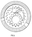
- FIG. 4 largely corresponds to that according to FIGS. 1 and 2; the only difference is that instead of a divided filler 4 an undivided filler 4 'is selected, in the axial side surfaces of which the bearing body receiving grooves are incorporated.
Applications Claiming Priority (2)
| Application Number | Priority Date | Filing Date | Title |
|---|---|---|---|
| DE3723557 | 1987-07-16 | ||
| DE19873723557 DE3723557A1 (de) | 1987-07-16 | 1987-07-16 | Innenzahnradmaschine |
Publications (2)
| Publication Number | Publication Date |
|---|---|
| EP0302190A1 true EP0302190A1 (fr) | 1989-02-08 |
| EP0302190B1 EP0302190B1 (fr) | 1991-03-20 |
Family
ID=6331718
Family Applications (1)
| Application Number | Title | Priority Date | Filing Date |
|---|---|---|---|
| EP88108387A Expired - Lifetime EP0302190B1 (fr) | 1987-07-16 | 1988-05-26 | Machine à engrenages à denture intérieure |
Country Status (4)
| Country | Link |
|---|---|
| US (1) | US4893997A (fr) |
| EP (1) | EP0302190B1 (fr) |
| JP (1) | JPH0747955B2 (fr) |
| DE (2) | DE3723557A1 (fr) |
Families Citing this family (4)
| Publication number | Priority date | Publication date | Assignee | Title |
|---|---|---|---|---|
| DE4336966A1 (de) * | 1993-10-29 | 1995-05-04 | Otto Eckerle | Innenzahnradmaschine |
| DE19815421A1 (de) * | 1998-04-07 | 1999-10-14 | Eckerle Ind Elektronik Gmbh | Innenzahnradmaschine |
| DE10058883A1 (de) | 1999-12-08 | 2001-07-12 | Luk Lamellen & Kupplungsbau | Zahnradmaschine |
| DE202013103826U1 (de) | 2013-05-13 | 2013-09-09 | Eckerle Industrie-Elektronik Gmbh | Innenzahnradmaschine mit Füllstück-Rückhalteeinrichtung |
Citations (3)
| Publication number | Priority date | Publication date | Assignee | Title |
|---|---|---|---|---|
| DE2223916A1 (de) * | 1972-05-17 | 1973-11-29 | Friedrich Reichert Gmbh Maschf | Innenverzahnte zahnradpumpe fuer hohe druecke |
| CH601670A5 (fr) * | 1975-10-27 | 1978-07-14 | Sperry Rand Corp | |
| DE3047609A1 (de) * | 1979-12-17 | 1981-09-17 | Kabushiki Kaisha Fujikoshi t/a Nachi-Fujikoshi Corp., Toyama | "innenzahnradpumpe bzw. -motor" |
Family Cites Families (6)
| Publication number | Priority date | Publication date | Assignee | Title |
|---|---|---|---|---|
| DE1553015B2 (de) * | 1963-04-11 | 1977-04-21 | Eckerle, Otto, 7502 Maisch | Verschleissausgleichende, innenachsige zahnradpumpe |
| DE2313085C2 (de) * | 1973-03-16 | 1984-05-24 | Otto 7502 Malsch Eckerle | Axial und radial kompensierte Hochdruck-Zahnradpumpe |
| DE2606082A1 (de) * | 1976-02-16 | 1977-08-25 | Otto Eckerle | Hochdruck-zahnradpumpe oder -motor |
| US4132515A (en) * | 1975-10-27 | 1979-01-02 | Kruger Heinz W | Crescent gear pump or motor having bearing means for supporting the ring gear |
| DE2942417A1 (de) * | 1979-10-19 | 1981-05-14 | Otto Eckerle GmbH & Co KG, 7502 Malsch | Innenzahnradmaschine |
| DE3544857C2 (de) * | 1985-12-18 | 1994-09-29 | Eckerle Rexroth Gmbh Co Kg | Innenzahnradmaschine |
-
1987
- 1987-07-16 DE DE19873723557 patent/DE3723557A1/de not_active Withdrawn
-
1988
- 1988-05-26 EP EP88108387A patent/EP0302190B1/fr not_active Expired - Lifetime
- 1988-05-26 DE DE8888108387T patent/DE3862079D1/de not_active Expired - Lifetime
- 1988-07-01 US US07/214,194 patent/US4893997A/en not_active Expired - Lifetime
- 1988-07-15 JP JP63176863A patent/JPH0747955B2/ja not_active Expired - Fee Related
Patent Citations (3)
| Publication number | Priority date | Publication date | Assignee | Title |
|---|---|---|---|---|
| DE2223916A1 (de) * | 1972-05-17 | 1973-11-29 | Friedrich Reichert Gmbh Maschf | Innenverzahnte zahnradpumpe fuer hohe druecke |
| CH601670A5 (fr) * | 1975-10-27 | 1978-07-14 | Sperry Rand Corp | |
| DE3047609A1 (de) * | 1979-12-17 | 1981-09-17 | Kabushiki Kaisha Fujikoshi t/a Nachi-Fujikoshi Corp., Toyama | "innenzahnradpumpe bzw. -motor" |
Also Published As
| Publication number | Publication date |
|---|---|
| DE3862079D1 (de) | 1991-04-25 |
| EP0302190B1 (fr) | 1991-03-20 |
| US4893997A (en) | 1990-01-16 |
| JPS6445986A (en) | 1989-02-20 |
| DE3723557A1 (de) | 1989-01-26 |
| JPH0747955B2 (ja) | 1995-05-24 |
Similar Documents
| Publication | Publication Date | Title |
|---|---|---|
| DE1958225C3 (de) | Außeneingriffszahnradpumpe | |
| EP1078165B1 (fr) | Ensemble compresseur en spirale | |
| DE19613833B4 (de) | Innenzahnradmaschine, insbesondere Innenzahnradpumpe | |
| DE2731474C2 (de) | Axial- bzw. Radialkolbenmaschine | |
| DE1906057B2 (de) | Rotationskolbenmaschine mit Schraubenrotor und Dichtungszahnrad für gasförmige und flüssige Medien | |
| DE102005041579B4 (de) | Innenzahnradpumpe mit Füllstück | |
| CH626951A5 (fr) | ||
| DE2217076A1 (de) | Zahnradpumpe | |
| DE19527647A1 (de) | Axialkolbenmaschine | |
| DE2000477A1 (de) | Hydraulische Pumpe oder Motor | |
| DE2710734A1 (de) | Verdichter mit exzentrisch gefuehrten, frei beweglichen kolben | |
| EP0302190B1 (fr) | Machine à engrenages à denture intérieure | |
| DE1264958B (de) | Zahnradpumpe oder -motor | |
| DE1653810C3 (de) | Zahnradpumpe | |
| DE1553035C3 (de) | Innenläuferzahnradpumpe mit radial beweglichem Füllstück | |
| EP0189786B1 (fr) | Machine à pistons axiaux | |
| DE102004021216B4 (de) | Hochdruck-Innenzahnradmaschine mit mehrfacher hydrostatischer Lagerung pro Hohlrad | |
| DE19620654B4 (de) | Verstellbare Axialkolbenmaschine in Schrägscheibenbauweise | |
| DE4135725A1 (de) | Innenzahnradpumpe mit zwei hohlraedern und einem gemeinsamen ritzel | |
| DE2735582C3 (de) | Kolbenpumpe | |
| DE2254751C3 (fr) | ||
| DE3729319C2 (de) | Spiralverdichter | |
| DE2643770A1 (de) | Hydraulische maschine mit axial angeordneten kolben | |
| DE2157725C3 (de) | Zahnradpumpe | |
| DE2438512C3 (de) | Zahnradmaschine |
Legal Events
| Date | Code | Title | Description |
|---|---|---|---|
| PUAI | Public reference made under article 153(3) epc to a published international application that has entered the european phase |
Free format text: ORIGINAL CODE: 0009012 |
|
| AK | Designated contracting states |
Kind code of ref document: A1 Designated state(s): DE FR GB IT |
|
| 17P | Request for examination filed |
Effective date: 19890315 |
|
| 17Q | First examination report despatched |
Effective date: 19890906 |
|
| GRAA | (expected) grant |
Free format text: ORIGINAL CODE: 0009210 |
|
| AK | Designated contracting states |
Kind code of ref document: B1 Designated state(s): DE FR GB IT |
|
| ET | Fr: translation filed | ||
| REF | Corresponds to: |
Ref document number: 3862079 Country of ref document: DE Date of ref document: 19910425 |
|
| ITF | It: translation for a ep patent filed |
Owner name: STUDIO TORTA SOCIETA' SEMPLICE |
|
| GBT | Gb: translation of ep patent filed (gb section 77(6)(a)/1977) | ||
| PLBE | No opposition filed within time limit |
Free format text: ORIGINAL CODE: 0009261 |
|
| STAA | Information on the status of an ep patent application or granted ep patent |
Free format text: STATUS: NO OPPOSITION FILED WITHIN TIME LIMIT |
|
| 26N | No opposition filed | ||
| REG | Reference to a national code |
Ref country code: FR Ref legal event code: CD |
|
| ITPR | It: changes in ownership of a european patent |
Owner name: CAMBIO RAGIONE SOCIALE;ECKERLE REXROTH GMBH & CO. |
|
| REG | Reference to a national code |
Ref country code: FR Ref legal event code: TP |
|
| REG | Reference to a national code |
Ref country code: GB Ref legal event code: 732E |
|
| REG | Reference to a national code |
Ref country code: GB Ref legal event code: IF02 |
|
| PGFP | Annual fee paid to national office [announced via postgrant information from national office to epo] |
Ref country code: GB Payment date: 20020502 Year of fee payment: 15 |
|
| PGFP | Annual fee paid to national office [announced via postgrant information from national office to epo] |
Ref country code: FR Payment date: 20020517 Year of fee payment: 15 |
|
| PG25 | Lapsed in a contracting state [announced via postgrant information from national office to epo] |
Ref country code: GB Free format text: LAPSE BECAUSE OF NON-PAYMENT OF DUE FEES Effective date: 20030526 |
|
| GBPC | Gb: european patent ceased through non-payment of renewal fee |
Effective date: 20030526 |
|
| PG25 | Lapsed in a contracting state [announced via postgrant information from national office to epo] |
Ref country code: FR Free format text: LAPSE BECAUSE OF NON-PAYMENT OF DUE FEES Effective date: 20040130 |
|
| REG | Reference to a national code |
Ref country code: FR Ref legal event code: ST |
|
| PG25 | Lapsed in a contracting state [announced via postgrant information from national office to epo] |
Ref country code: IT Free format text: LAPSE BECAUSE OF NON-PAYMENT OF DUE FEES;WARNING: LAPSES OF ITALIAN PATENTS WITH EFFECTIVE DATE BEFORE 2007 MAY HAVE OCCURRED AT ANY TIME BEFORE 2007. THE CORRECT EFFECTIVE DATE MAY BE DIFFERENT FROM THE ONE RECORDED. Effective date: 20050526 |
|
| PGFP | Annual fee paid to national office [announced via postgrant information from national office to epo] |
Ref country code: DE Payment date: 20070508 Year of fee payment: 20 |