EP0302190A1 - Internal-gear machine - Google Patents
Internal-gear machine Download PDFInfo
- Publication number
- EP0302190A1 EP0302190A1 EP88108387A EP88108387A EP0302190A1 EP 0302190 A1 EP0302190 A1 EP 0302190A1 EP 88108387 A EP88108387 A EP 88108387A EP 88108387 A EP88108387 A EP 88108387A EP 0302190 A1 EP0302190 A1 EP 0302190A1
- Authority
- EP
- European Patent Office
- Prior art keywords
- filler
- internal gear
- machine according
- bearing
- gear machine
- Prior art date
- Legal status (The legal status is an assumption and is not a legal conclusion. Google has not performed a legal analysis and makes no representation as to the accuracy of the status listed.)
- Granted
Links
Images


Classifications
-
- F—MECHANICAL ENGINEERING; LIGHTING; HEATING; WEAPONS; BLASTING
- F04—POSITIVE - DISPLACEMENT MACHINES FOR LIQUIDS; PUMPS FOR LIQUIDS OR ELASTIC FLUIDS
- F04C—ROTARY-PISTON, OR OSCILLATING-PISTON, POSITIVE-DISPLACEMENT MACHINES FOR LIQUIDS; ROTARY-PISTON, OR OSCILLATING-PISTON, POSITIVE-DISPLACEMENT PUMPS
- F04C2/00—Rotary-piston machines or pumps
- F04C2/08—Rotary-piston machines or pumps of intermeshing-engagement type, i.e. with engagement of co-operating members similar to that of toothed gearing
- F04C2/10—Rotary-piston machines or pumps of intermeshing-engagement type, i.e. with engagement of co-operating members similar to that of toothed gearing of internal-axis type with the outer member having more teeth or tooth-equivalents, e.g. rollers, than the inner member
- F04C2/101—Rotary-piston machines or pumps of intermeshing-engagement type, i.e. with engagement of co-operating members similar to that of toothed gearing of internal-axis type with the outer member having more teeth or tooth-equivalents, e.g. rollers, than the inner member with a crescent-shaped filler element, located between the inner and outer intermeshing members
Definitions
- the invention relates to an internal gear machine, in particular an internal gear pump, with the features according to the preamble of patent claim 1.
- the filler piece is mounted so flexibly in internal gear machines of the type specified above (cf. DE-OS 15 53 027; CH-PS 601 670) that it can follow the movements of the meshing gears during operation in order to create radial leakage gaps resulting from the movement balance.
- internal gear machines of the type specified above (cf. DE-OS 15 53 027; CH-PS 601 670) that it can follow the movements of the meshing gears during operation in order to create radial leakage gaps resulting from the movement balance.
- the invention is therefore based on the object to provide an internal gear machine of the type specified, in particular for the promotion of low-viscosity media, which is not subject to the restrictions described with regard to the level of the operating pressure, but without the risk of overloading the filler bearing and the risk of being pulled in of the filler in the tooth mesh is excluded with certainty.
- the invention is based on the consideration that a greater freedom in the arrangement of the bearing body is obtained by relocating the filler bearing from the suction chamber end towards the filler tip, so that on the one hand the bearing body has the largest possible storage area and, as a result, a corresponding one low surface pressure can be realized, but on the other hand it can also be ensured that the resultant of the hydraulic forces acting on the filler from the pressure chamber also passes through the bearing surface without the pressure chamber having to be enlarged unnecessarily. It goes without saying that with increasing operating pressure there must be an interest in keeping the pressure space as small as possible in order to keep the load on the internal gear machine within limits.
- the bearing journal is expediently arranged in the filler half facing the suction chamber end of the filler and, in the limit case, lies in the longitudinal center of the filler.
- Favorable kinematic conditions for the radial gap compensation are also obtained if the axis of rotation of the bearing pin passes through the filler at a point closer to the circumferential surface of the ring gear.
- the bearing body is designed asymmetrically with respect to the axis of rotation of the bearing pin, since it is offset relative to the filler piece relative to the filler piece in accordance with the eccentric arrangement of the bearing pin axis.
- the storage of the filling piece which is offset towards the filling piece tip, allows greater freedom in the orientation of the bearing surface.
- the bearing surface and the groove receiving the bearing body in the side surface of the filling piece will always be placed in such a way that an optimal distribution of the filling piece on the one hand in Direction of the pinion, on the other hand, forces urging in the direction of the ring gear.
- this always enables a compromise, which leads to a relatively large storage area and the resulting low surface pressure.
- the bearing body which is expediently one-piece with the journal, has two mutually parallel flat surfaces, of which the bearing surface facing the filler tip assumes the support of the filler against the hydraulic and other forces that are effective during operation, while the surface facing the suction chamber is the retention surface , which absorbs the forces acting on the filler from the suction chamber and the frictional forces exerted on the filler by the gearwheels. Since these opposing forces do not coincide in terms of direction, it can be thought, in particular in the case of a long filler piece in which the proportion of frictional force is greater, that the bearing surfaces on the bearing body run at a corresponding angle to one another, this angle normally being in Direction towards the ring gear opens.
- the cross-section of the bearing body is thus wedge-shaped in this case, the suction-space-side retention surface being positioned such that the pressure forces acting from the suction space and the frictional forces are directed perpendicularly or almost perpendicularly to this surface.
- the game between the filler and this retaining surface can always be kept small even with a plan-parallel arrangement of the bearing surface and the retaining surface.
- this is possible to a particular degree, since the play decreases when the filler moves in the direction of the ring gear due to the wedge shape.
- the configuration according to the invention can in principle also be used for multi-part filling pieces (cf. DE-OS 26 06 082).
- the groove provided on the side of the filler expediently penetrates all parts or segments of the filler.
- the retaining surface of the bearing body is not a flat surface, but has a kink at the separation point between the sealing segment and segment carrier on. This takes into account the fact that the seg ment carrier and forces acting on the sealing segment from the suction space and the frictional forces have different directions. In order to align the retaining surface in the sense already explained above so that these forces are absorbed vertically, this adjustment is necessary.
- the internal gear pump according to FIG. 1 has a housing 1 (not shown in more detail), an internal gear or ring gear 2 mounted therein with its circumference, a pinion 3 mounted in the housing and equipped with a shaft (not shown), and a filling piece designated as 4 overall.
- the ring gear 2 bears on its entire circumference in a known manner only partially indicated openings 5, which enables the pumped medium that enters through a suction opening 6 to get into the suction chamber 7 and out of the pressure chamber 8 exit again, after which it is discharged through a pressure connection 9.
- the structure of the internal gear pump described so far is conventional and therefore requires no further explanation.
- the filler 4 has the shape of a half-crescent or a comma and is made relatively long in the embodiment shown, so that it is in contact with nine teeth of the ring gear 2 on its outer circumferential surface at the same time in order to promote the best possible low-viscosity media Get waterproofing.
- the filler 4 is composed of a shell-shaped sealing segment 11 and a segment carrier 12, which abut one another along a separating surface 13 which extends in the circumferential direction and are sealed off from one another by two sealing rollers 14.
- two lateral housing plates 15, which are only indicated in FIG. 2 blind bores 16 are formed for the rotatable mounting of one bearing pin 17 each.
- the bearing pins 17 are assigned to the two side surfaces of the filler piece 4 and have bearing bodies 18 formed integrally thereon, which project in the direction of the filler piece from the end face of the bearing pins 17.
- the bearing bodies 18 have two plane-parallel surfaces, of which the surface 19 facing the filler tip is the bearing surface for absorbing the forces acting from the pressure chamber 8 and the opposite surface 20 is the retaining surface for supporting the filler 4 against the forces acting from the suction chamber 7 .
- the journals 17 are arranged relative to the filler 4 in such a way that the axis of rotation 20 of the journals 17 is offset in the direction toward the syringe of the filler 4 and is located at a point that the filler length is approximately in the ratio of 2 to 3 shares.
- the axis of rotation 20 is close to the interface 13 between the sealing segment 11 and segment carrier 12, i.e. thus closer to the tooth tips of the ring gear 2.
- grooves 21 corresponding to the bearing bodies 18 are incorporated, which are intended for receiving the bearing bodies 18 and their groove flanks on the bearing surface 19 and on of the retaining surface 20 and transfer the forces acting on the filler 4 to this.
- the shape of the grooves 21 and the bearing bodies 18 engaging therein results from FIG. 1, from which it can be seen that, due to the eccentric arrangement of the axis of rotation 20 relative to the filler 4, the bearing bodies 18 are eccentric with respect to the end face of the journal 17 in the direction of the pinion 3 are arranged. It can also be seen from FIG.
- the bearing body 18 largely fills the grooves 21 of the filler 4, that is to say that they are at least approximately matched to the circumferential shape of the filler 4 on their circumferential boundary surfaces in order thereby to keep the surfaces 19 and 20 as large as possible.
- the groove flanks of the grooves 21, as can also be seen in FIG. 1, run at an angle of approximately 30 degrees to the plane in which the axis of the pinion 3 and the axis of rotation 20 of the bearing pins 17 lie.
- This bearing ensures that, on the one hand, the forces acting on the filler 4 from the pressure chamber 8 are distributed such that the filler experiences an optimal sealing system on the ring gear 2 and on the pinion 3, and on the other hand the surface pressure which arises on the bearing surface 19 is as low as possible .
- the direction of the resultant force of the hydraulic forces acting from the pressure chamber 8 is defined in a known manner by control slots, not shown, in the axial plates 15 and / or the side faces of the filler 4 (cf. DE-OS 15 53
- the embodiment according to FIG. 2A differs from the embodiment described above only in that instead of two bearing journals 17 assigned to the two side faces of the filling piece 4, only a bearing journal 17 ′ which is arranged on one side and is provided with its bearing body 18 ′ in a groove 21 ′ arranged on one side is provided. of the filler engages.
- FIG. 3 differs from the embodiment according to FIGS. 1 and 2 solely by the special design of the bearing body 28 on the bearing journal 27. For this reason, the other components of the internal gear pump are identified by the same reference numerals as in FIGS. 1 and 2 .
- the bearing surface 29 - as in the first embodiment - is arranged at an angle of approximately 30 degrees to the plane containing the axis of rotation of the bearing journal 27 and the pinion 3 and is designed to be flat throughout.
- the retention surface 30, however, forms an acute angle to the bearing surface 29 and is divided into a partial surface 30 'assigned to the segment carrier 22 and a partial surface 30' assigned to the sealing segment 23.
- the partial surfaces 30 'and 30 ⁇ meet in the area of the separating surface 13; the retention surface 30 is thus kinked.
- This embodiment takes into account the fact that the forces acting from the suction space 7 act on the segment carrier 22 and the sealing segment 23 in different directions, so that it is necessary to incline them differently in the case of a vertical alignment of the respectively associated retaining surfaces.
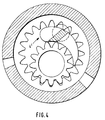
- FIG. 4 largely corresponds to that according to FIGS. 1 and 2; the only difference is that instead of a divided filler 4 an undivided filler 4 'is selected, in the axial side surfaces of which the bearing body receiving grooves are incorporated.
Abstract
Eine Innenzahnradpumpe mit einem innenverzahnten Hohlrad (2), einem damit in Eingriff stehenden außenverzahnten Ritzel (3) und einem halbsichelförmigen Füllstück (4). Das Füllstück (4) ist drehbar und verschiebbar mittels mindestens eines Lagerzapfens im Gehäuse gelagert, der in einem Abstand vom saugraumseitigen Ende des Füllstückes angeordnet ist und einen Lagerkörper (18) aufweist, welcher in eine Nut in der Seitenfläche des Füllstücks (4) eingreift. Durch diese Art der Lagerung des Füllstückes können ohne Überlastung des Lagerzapfens und das Lagerkörpers (18) höhere Betriebsdrücke erzielt werden und die Gefahr eines Hineinziehens des Füllstückes in den Zahneingriff wird vermieden.An internal gear pump with an internal toothed ring gear (2), an external toothed pinion (3) in engagement with it and a semi-crescent shaped filler (4). The filler (4) is rotatably and displaceably mounted in the housing by means of at least one bearing pin, which is arranged at a distance from the end of the filler on the suction chamber side and has a bearing body (18) which engages in a groove in the side surface of the filler (4). With this type of mounting of the filler, higher operating pressures can be achieved without overloading the bearing journal and the bearing body (18) and the risk of the filler being pulled into the tooth engagement is avoided.
Description
Die Erfindung betrifft eine Innenzahnradmaschine, insbesondere Innenzahnradpumpe, mit den Merkmalen gemäß dem Oberbegriff des Patentanspruches 1.The invention relates to an internal gear machine, in particular an internal gear pump, with the features according to the preamble of
Das Füllstück ist in Innenzahnradmaschinen der vorstehend angegebenen Art (vgl. DE-OS 15 53 027; CH-PS 601 670) so beweglich gelagert, daß es im Betrieb den Bewegungen der miteinander kämmenden Zahnräder folgen kann, um hierdurch aufgrund der Bewegung entstehende radiale Leckspalte auszugleichen. Durch eine gezielte Steuerung der auf das Füllstück einwirkenden hydraulischen Kräfte, die mittels am Füllstück und/oder an den daran anliegenden Flächen vorgesehener Vorfüllnuten oder -schlitze erfolgt (vgl. DE-OS 15 53 027) wird dafür gesorgt, daß das Füllstück zumindest teilweise durch das Einwirken der hydraulischen Kräfte in der für die Dichtung jeweils optimalen Lage gehalten, d.h. an die Zahnköpfe der Zahnräder angedrückt wird. Die Richtung und die Größe dieser Kräfte werden aufgrund der genannten Steuerung dabei durch die Höhe des im Druckraum herrschenden Betriebsdruckes sowie durch den Verlauf der durch die Steuerung bestimmten Trennfläche zwischen Saugraum und Druckraum bestimmt. Eindeutig bestimmt sind diese Kräfte, jedoch genau genommen nur bei stationärem Betrieb der Zahnradmaschine. Herrscht hingegen kein Betriebsdruck im Druckraum oder treten Betriebszustände ein, bei denen der Druck im Saugraum sogar den Druck im Druckraum übersteigt (was beim Einsatz von vorgeschalteten Füllpumpen der Fall sein kann), dann wirken auf das Füllstück Kräfte ein, die dieses in Richtung auf den Zahneingriff der miteinander kämmenden Zahnräder drücken. In Verbindung mit den ohnehin in dieser Richtung auf das Füllstück einwirkenden Reibkräften zwischen Füllstück und Zahnköpfen besteht dabei die Gefahr, daß das Füllstück von den Zahnrädern mitgenommen wird und sich im Zahneingriff verkeilt. Dies hat die sofortige Blockierung und damit den Ausfall des angeschlossenen Geräts zur Folge.The filler piece is mounted so flexibly in internal gear machines of the type specified above (cf. DE-OS 15 53 027; CH-PS 601 670) that it can follow the movements of the meshing gears during operation in order to create radial leakage gaps resulting from the movement balance. Through a targeted control of the hydraulic forces acting on the filler, which takes place by means of pre-filling grooves or slots provided on the filler and / or on the surfaces lying against it (cf. DE-OS 15 53 027), it is ensured that the filler is at least partially by the action of the hydraulic forces is held in the optimal position for the seal, ie it is pressed against the tooth tips of the gears. The direction and the magnitude of these forces are determined on the basis of the control mentioned by the level of the operating pressure prevailing in the pressure chamber and by the course of the interface between the suction chamber and the pressure chamber determined by the control. These forces are clearly determined, but strictly speaking only when the gear machine is in stationary operation. If, on the other hand, there is no operating pressure in the pressure chamber or operating conditions occur in which the pressure in the suction chamber even exceeds the pressure in the pressure chamber (which can be the case when using upstream filling pumps), then forces act on the filler in the direction of this press the meshing of the meshing gears. In connection with the frictional forces acting in this direction on the filler piece between the filler piece and the tooth heads, there is a risk that the filler piece will be carried along by the gears and wedged in meshing engagement. This results in immediate blocking and thus the failure of the connected device.
Um ein derartiges Verkeilen zu vermeiden, ist es bereits bekannt, das Füllstück in der eingangs angegebenen Art zu lagern, so daß es in beiden Umfangsrichtungen gehalten ist, ohne daß dadurch die freie Beweglichkeit zum Zweck der Radialspaltkompensation beeinträchtigt ist. Nachteilig ist bei dieser Ausführung jedoch, daß der das Füllstück durchsetzende Lagerzapfen entsprechend den Füllstückabmessungen in seinem Durchmesser begrenzt ist und daher hohe Betriebsdrücke nicht verträgt. Um höhere Betriebsdrücke verwirklichen zu können, ist man deshalb schon zu Lagerzapfen für das Füllstück übergegangen, die ganz außerhalb des Füllstückes verlaufen, eine Abstützfläche für das Füllstück aufweisen und aus diesem Grund stärker ausgeführt werden können. Um aber hierbei das Verkeilen zu vermeiden, wurde zusätzlich zur Rückhaltung des Füllstückes ein Federstift vorgesehen (DE-OS 23 13 085). Bei den vorstehend geschilderten Betriebzuständen, in denen ein im Saugraum überwiegender Druck herrscht, kann aber auch durch den Federstift ein Hineinziehen des Füllstückes in den Zahneingriff bei laufender Maschine nicht mit Sicherheit ausgeschlossen werden. Dies gilt noch in verstärktem Maße in solchen Fällen, in denen das Fördermedium sehr dünnflüssig und gegebenenfalls zusätzlich noch nichtschmierend ist.In order to avoid such wedging, it is already known to store the filling piece in the manner specified at the outset, so that it is held in both circumferential directions without the free mobility for the purpose of radial gap compensation being impaired thereby. A disadvantage of this embodiment, however, is that the diameter of the bearing pin passing through the filler piece is limited in accordance with the filler piece dimensions and therefore cannot tolerate high operating pressures. In order to be able to achieve higher operating pressures, bearings for the filler piece have already been moved to, which run completely outside the filler piece, have a support surface for the filler piece and can therefore be made stronger. In order to avoid wedging, a spring pin was provided in addition to retaining the filler (DE-OS 23 13 085). In the operating conditions described above, in which there is a predominant pressure in the suction chamber, a pulling of the filler into the tooth engagement while the machine is running cannot also be ruled out with certainty by the spring pin. This applies to an even greater extent in those cases in which the pumped medium is very thin and possibly additionally non-lubricating.
Denn bei solchen Fördermedien ist es aus Gründen der Abdichtung erforderlich, das Füllstück länger als an Innenzahnradmaschinen für Fördermedien von höherer Viskosität auszubilden, was aber den gleichzeitigen Eingriff einer höheren Zahl von Zahnköpfer mit dem Füllstück und eine daraus resultierende höhere Reibkraft zur Folge hat, die das Füllstück in den Zahneingriff zu ziehen sucht.Because with such conveying media it is necessary for sealing reasons to make the filler longer than on internal gear machines for conveying media of higher viscosity, but this results in the simultaneous engagement of a higher number of tooth tips with the filler and a resulting higher frictional force, which Trying to pull the filler into the tooth mesh.
Der Erfindung liegt daher die Aufgabe zugrunde, eine Innenzahnradmaschine der eingangs angegebenen Art zu schaffen, insbesondere zur Förderung dünnflüssiger Medien, die den geschilderten Beschränkungen bezüglich der Höhe des Betriebsdruckes nicht unterliegt, ohne daß aber die Gefahr einer Überbelastung der Füllstücklagerung besteht und die Gefahr eines Hineinziehens des Füllstückes in den Zahneingriff mit Sicherheit ausgeschlossen ist.The invention is therefore based on the object to provide an internal gear machine of the type specified, in particular for the promotion of low-viscosity media, which is not subject to the restrictions described with regard to the level of the operating pressure, but without the risk of overloading the filler bearing and the risk of being pulled in of the filler in the tooth mesh is excluded with certainty.
Erfindungsgemäß wird diese Aufgabe gelöst durch die Merkmale gemäß dem Kennzeichen des Patenanspruches 1.According to the invention, this object is achieved by the features according to the characterizing part of
Die Erfindung geht dabei von der Überlegung aus, daß man durch eine Verlegung der Füllstücklagerung von dem saugraumseitigen Ende in Richtung auf die Füllstückspitze eine größere Freiheit bei der Anordnung des Lagerkörpers erhält, so daß einerseits an dem Lagerkörper eine möglichst große Lagerfläche und daraus resultierend eine entsprechend niedrige Flächenpressung verwirklicht werden kann, andererseits aber auch dafür gesorgt werden kann, daß die Resultierende der vom Druckraum her an dem Füllstück angreifenden hydraulischen Kräfte auch durch die Lagerfläche geht, ohne daß der Druckraum unnötig vergrößert werden muß. Es versteht sich, daß mit zunehmendem Betriebsdruck ein Interesse daran bestehen muß, den Druckraum möglichst klein zu halten, um hierdurch die Belastung der Innenzahnradmaschine in Grenzen zu halten. Insbesondere bei Füllstücken, die aus den oben angegebenen Gründen länger ausgebildet sein müssen, läßt sich eine Ausrichtung der hydraulischen Kraftresultierenden auf die Lagerfläche für das Füllstück aber nur unter Inkaufnahme einer Vergrößerung des Druckraumes erreichen, weil hierzu die Trennfläche zwischen Saugraum und Druckraum am Füllstück mittels der erwähnten Steuerung weiter von der Füllstückspritze entfernt angeordnet werden muß. Die erfinungsgemäße Ausbildung, bei der das Füllstück praktisch über seine Abstützung hinaus in Richtung Saugraum verlängert ist, erlaubt es jedoch, die Kraftresulierende auf die Lagerfläche des Lagerkörpers zu richten, ohne eine Vergrößerung des Druckraumes hinnehmen zu müssen. Weiterhin kann der Lagerkörper an dem Lagerzapfen beliebig an dessen Stirnseite, auch exzentrisch, je nach der Lage der Nut in der Seitenfläche des Füllstückes angeordnet sein, so daß jeweils eine maximale Abstützfläche zur Verfügung steht.The invention is based on the consideration that a greater freedom in the arrangement of the bearing body is obtained by relocating the filler bearing from the suction chamber end towards the filler tip, so that on the one hand the bearing body has the largest possible storage area and, as a result, a corresponding one low surface pressure can be realized, but on the other hand it can also be ensured that the resultant of the hydraulic forces acting on the filler from the pressure chamber also passes through the bearing surface without the pressure chamber having to be enlarged unnecessarily. It goes without saying that with increasing operating pressure there must be an interest in keeping the pressure space as small as possible in order to keep the load on the internal gear machine within limits. Especially with filler pieces, which must be longer for the reasons given above, an alignment of the hydraulic force results on the bearing surface for the filler piece can only be achieved by accepting an enlargement of the pressure chamber, because for this purpose the separating surface between the suction chamber and the pressure chamber on the filler piece by means of mentioned control must be placed further away from the filling syringe. The inventive design, in which the filler is practically extended beyond its support in the direction of the suction chamber, however, allows the resultant force to be aimed at the bearing surface of the bearing body without having to accept an increase in the pressure chamber. Furthermore, the bearing body on the trunnion at its end face, also eccentrically, depending be arranged according to the position of the groove in the side surface of the filler piece, so that a maximum support surface is available in each case.
Es ist zwar bereits von Innenzahnradmaschinen, bei denen ein Füllstück in Form einer vollständigen Sichel mit zwei spitz zu laufenden Enden vorgesehen ist, bekannt, dieses Füllstück in der Längsmitte an einem Füllstückstift zu lagern. Infolge der symetrischen Ausbildung und der beidseitigen Verjüngung dieses Füllstückes ist aber die mittige Lagerung im Bereich der größten Füllstückdicke die einzig sinnvolle und entspricht bei den Innenzahnradmaschinen mit halbsichelförmigem Füllstück der bisher gebräuchlichen Lagerung am saugraumseitigen Füllstückende.It is already known from internal gear machines in which a filler piece is provided in the form of a complete sickle with two pointed ends, to store this filler piece in the longitudinal center on a filler pin. As a result of the symmetrical design and the tapering of this filler on both sides, the central bearing in the area of the greatest filler thickness is the only sensible one and corresponds to the hitherto customary storage at the end of the suction piece on the internal gear machines with a semi-crescent shaped filler.
Der Lagerzapfen ist zweckmäßigerweise in der dem saugraumseitigen Ende des Füllstückes zugewendeten Füllstückhälfte angeordnet und liegt im Grenzfall in der Längsmitte des Füllstückes. Günstige kinematische Verhältnisse für die Radialspaltkompensation erhält man darüber hinaus, wenn die Drehachse des Lagerzapfens das Füllstück an einer Stelle durchsetzt, die näher an dessen hohlradseitiger Umfangsfläche liegt. Bei dieser Ausführung ist der Lagerkörper bezüglich der Drehachse des Lagerzapfens unsymetrisch ausgestaltet, da er entsprechend der außermittigen Anordnung der Lagerzapfenachse relativ zum Füllstück zu letzterem hinversetzt ist.The bearing journal is expediently arranged in the filler half facing the suction chamber end of the filler and, in the limit case, lies in the longitudinal center of the filler. Favorable kinematic conditions for the radial gap compensation are also obtained if the axis of rotation of the bearing pin passes through the filler at a point closer to the circumferential surface of the ring gear. In this embodiment, the bearing body is designed asymmetrically with respect to the axis of rotation of the bearing pin, since it is offset relative to the filler piece relative to the filler piece in accordance with the eccentric arrangement of the bearing pin axis.
Wie bereits erwähnt, ermöglicht die zur Füllstückspitze hin versetzte Lagerung des Füllstückes eine größere Freiheit bei der Orientierung der Lagerfläche. In Verbindung mit der durch Steuerschlitze oder Vorfüllnuten erfolgenden Beeinflussung von Richtung und Größe der auf das Füllstück wirkenden hydraulischen Kraftresultierenden wird man aber die Lagerfläche und die den Lagerkörper aufnehmende Nut in der Seitenfläche des Füllstückes immer so legen, daß eine optimale Verteilung der das Füllstück einerseits in Richtung des Ritzels andererseits in Richtung des Hohlrades drängenden Kräfte erfolgt. Dies ermöglicht jedoch stets einen Kompromiß, der zu einer relativ großen Lagerfläche und daraus resultierender niedriger Flächenpressung führt.As already mentioned, the storage of the filling piece, which is offset towards the filling piece tip, allows greater freedom in the orientation of the bearing surface. In connection with the influencing of the direction and size of the hydraulic force results acting on the filling piece through control slots or pre-filling grooves, the bearing surface and the groove receiving the bearing body in the side surface of the filling piece will always be placed in such a way that an optimal distribution of the filling piece on the one hand in Direction of the pinion, on the other hand, forces urging in the direction of the ring gear. However, this always enables a compromise, which leads to a relatively large storage area and the resulting low surface pressure.
Der zweckmäßigerweise mit dem Lagerzapfen einstückige Lagerkörper weist in der einfachsten Ausführungsform zwei zueinander parallele ebene Fläche auf, von denen die der Füllstückspitze zugewendete Lagerfläche die Abstützung des Füllstückes gegenüber den im Betrieb wirksamen hydraulischen und sonstigen Kräften übernimmt, während die dem Saugraum zugewendete Fläche die Rückhaltefläche ist, die die vom Saugraum her auf das Füllstück wirkenden Kräfte sowie die von den Zahnrädern auf dieses ausgeübten Reibkräfte aufnimmt. Da sich richtungsmäßig diese einander entgegengesetzten Kräfte nicht decken, kann jedoch insbesondere bei einem lang ausgebildeten Füllstück, an dem der Reibkraftanteil größer ist, daran gedacht werden, die Lagerflächen an dem Lagerkörper unter einem entsprechenden Winkel zueinander verlaufen zu lassen, wobei dieser Winkel sich normalerweise in Richtung zum Hohlrad hin öffnet. Der Querschnitt des Lagerkörpers ist in diesem Fall somit keilförmig, wobei die saugraumseitige Rückhaltefläche so gelegt ist, daß die vom Saugraum her wirkenden Druckkräfte sowie die Reibkräfte senkrecht oder nahezu senkrecht zu dieser Fläche gerichtet sind. Das Spiel zwischen dem Füllstück und dieser Rückhaltefläche kann auch bei planparelleler Anordnung der Lagerflä che und der Rückhaltefläche stets klein gehalten werden. Bei der geschilderten Ausführungsform des Lagerkörpers mit keilförmigem Querschnitt ist dies in besonderem Maße möglich, da infolge der Keilform sich das Spiel bei Bewegungen des Füllstückes in Richtung Hohlrad verkleinert.In the simplest embodiment, the bearing body, which is expediently one-piece with the journal, has two mutually parallel flat surfaces, of which the bearing surface facing the filler tip assumes the support of the filler against the hydraulic and other forces that are effective during operation, while the surface facing the suction chamber is the retention surface , which absorbs the forces acting on the filler from the suction chamber and the frictional forces exerted on the filler by the gearwheels. Since these opposing forces do not coincide in terms of direction, it can be thought, in particular in the case of a long filler piece in which the proportion of frictional force is greater, that the bearing surfaces on the bearing body run at a corresponding angle to one another, this angle normally being in Direction towards the ring gear opens. The cross-section of the bearing body is thus wedge-shaped in this case, the suction-space-side retention surface being positioned such that the pressure forces acting from the suction space and the frictional forces are directed perpendicularly or almost perpendicularly to this surface. The game between the filler and this retaining surface can always be kept small even with a plan-parallel arrangement of the bearing surface and the retaining surface. In the described embodiment of the bearing body with a wedge-shaped cross section, this is possible to a particular degree, since the play decreases when the filler moves in the direction of the ring gear due to the wedge shape.
Die erfindungsgemäße Ausgestaltung kann grundsätzlich auch für mehrteilige Füllstücke Anwendung finden (vgl. DE-OS 26 06 082). In diesem Fall durchsetzt zweckmäßigerweise die an der Seite des Füllstückes vorgesehene Nut (bzw. die an beiden Seiten des Füllstückes vorgesehenen Nuten) alle Füllstückteile oder -segmente. In einer besonders bevorzugten Ausführungsform des Füllstückes, bei der sich dieses aus einem verhältnismäßig dünnwandigen Dichtsegment und aus einem Segmentträger zusammensetzt, wobei das Dichtsegment am Hohlrad anliegt, ist die Rückhaltefläche des Lagerkörpers keine ebene Fläche, sondern weist einen Knick an der Trennstelle zwischen Dichtsegment und Segmentträger auf. Hierdurch wird dem Umstand Rechnung getragen, daß die auf den Seg mentträger und auf das Dichtsegment vom Saugraum her wirkenden Kräfte sowie die Reibkräfte unterschiedliche Richtungen haben. Um in dem vorstehend bereits erläuterten Sinne die Rückhaltefläche so auszurichten, daß diese Kräfte senkrecht aufgenommen werden, ist diese Anpassung erforderlich.The configuration according to the invention can in principle also be used for multi-part filling pieces (cf. DE-OS 26 06 082). In this case, the groove provided on the side of the filler (or the grooves provided on both sides of the filler) expediently penetrates all parts or segments of the filler. In a particularly preferred embodiment of the filler piece, in which it is composed of a relatively thin-walled sealing segment and a segment carrier, the sealing segment resting on the ring gear, the retaining surface of the bearing body is not a flat surface, but has a kink at the separation point between the sealing segment and segment carrier on. This takes into account the fact that the seg ment carrier and forces acting on the sealing segment from the suction space and the frictional forces have different directions. In order to align the retaining surface in the sense already explained above so that these forces are absorbed vertically, this adjustment is necessary.
Weitere vorteilhafte Ausgestaltungen ergeben sich aus anderen Unteransprüchen.Further advantageous embodiments result from other subclaims.
Ausführungsbespiele der vorliegenden Erfindung sind nachfolgend anhand der beiliegenden Zeichnungen näher erläutert. In den Zeichnungen zeigen:
Figur 1 Einen schematischen Querschnitt durch eine erste Ausführungsform einer erfindungsgemäßen Innenzahnradpumpe mit geteiltem Füllstück;Figur 2 einen Teilschnitt längs der Linie II-II inFigur 1;- Figur 2A einen zu
Figur 2 analogen Teilschnitt an einer modifizierten Ausführungsform mit nur einem Lagerzapfen; - Figur 3 einen zu
Figur 1 analogen Querschnitt, jedoch nur teilweise, durch eine zweite Ausführungsform einer erfindungsgemäßen Innenzahnradpumpe, und - Figur 4 einen zu
Figur 1 analogen Querschnitt durch eine dritte Ausführungsform einer erfindungsgemäßen Innenzahnradpumpe mit einem einteiligen Füllstück.
- Figure 1 shows a schematic cross section through a first embodiment of an internal gear pump according to the invention with divided filler;
- 2 shows a partial section along the line II-II in Figure 1;
- FIG. 2A shows a partial section analogous to FIG. 2 on a modified embodiment with only one bearing journal;
- 3 shows a cross section analogous to FIG. 1, but only partially, through a second embodiment of an internal gear pump according to the invention, and
- 4 shows a cross section analogous to FIG. 1 through a third embodiment of an internal gear pump according to the invention with a one-piece filler.
Die Innenzahnradpumpe gemäß Figur 1 weist ein nicht näher gezeigtes Gehäuse 1, ein darin mit seinem Umfang gelagertes Innenzahnrad oder Hohlrad 2, ein im Gehäuse gelagertes und mit einer nicht gezeigten Welle ausgestattetes Ritzel 3 sowie ein im ganzen mit 4 bezeichnetes Füllstück auf. Das Hohlrad 2 trägt auf seinem ganzen Umfang in bekannter Weise nur zum Teil angedeutete Durchbrüche 5, die es dem Fördermedium, das über eine Ansaugöffnung 6 eintritt, ermöglicht in den Saugraum 7 zu gelangen und aus dem Druckraum 8 wieder auszutreten, wonach es durch einen Druckanschluß 9 abgeführt wird. Der bisher beschriebene Aufbau der Innenzahnradpumpe ist herkömmlicher Art und bedarf deshalb keiner näheren Erläuterung.The internal gear pump according to FIG. 1 has a housing 1 (not shown in more detail), an internal gear or
Das Füllstück 4 hat die Form einer Halbsichel oder eines Kommas und ist in dem gezeigten Ausführungsbeispiel verhältnismäßig lang ausgeführt, so daß es auf seiner äußeren Umfangsfläche gleichzeitig mit neun Zähnen des Hohlrades 2 in Kontakt steht, um zum Zweck der Förderung besonders dünnflüssiger Medien eine möglichst gute Abdichtung zu erhalten. Das Füllstück 4 setzt sich zusammen aus einem schalenförmigen Dichtsegment 11 und einem Segmentträger 12, die längs einer sich in Umfangsrichtung erstreckenden Trennfläche 13 aneinanderliegen und gegeneinander durch zwei Dichtwalzen 14 abgedichtet sind. In zwei seitlichen Gehäuseplatten 15, die in Figur 2 nur angedeutet sind, sind Sackbohrungen 16 zur drehbaren Lagerung je eines Lagerzapfens 17 ausgebildet. Die Lagerzapfen 17 sind den beiden Seitenflächen des Füllstückes 4 zugeordnet und weisen einstückig daran ausgebildete Lagerkörper 18 auf, die in Richtung auf das Füllstück von der Stirnseite der Lagerzapfen 17 vorspringen. Die Lagerkörper 18 haben zwei planparallele Flächen, von denen die der Füllstückspitze zugewendete Fläche 19 die Lagerfläche zur Aufnahme der aus dem Druckraum 8 wirkenden Kräfte und die gegenüberliegende Fläche 20 die Rückhaltefläche zur Abstützung des Füllstückes 4 gegenüber den Kräften ist, die vom Saugraum 7 her wirken. Wie sich aus Figur 1 ergibt, sind die Lagerzapfen 17 so relativ zum Füllstück 4 angeordnet, daß die Drehachse 20 der Lagerzapfen 17 in Richtung zur Spritze des Füllstückes 4 hin versetzt ist und an einer Stelle liegt, die die Füllstücklänge etwa im Verhältnis von 2 zu 3 teilt. Außerdem liegt die Drehachse 20 nahe an der Trennfläche 13 zwischen Dichtsegment 11 und Segmentträger 12, d.h. somit näher an den Zahnköpfen des Hohlrades 2.The filler 4 has the shape of a half-crescent or a comma and is made relatively long in the embodiment shown, so that it is in contact with nine teeth of the
In den axialen Seitenflächen des Dichtsegments 11 und des Segmentträgers 12 sind zu den Lagerkörpern 18 korrespondierende Nuten 21 eingearbeitet, die zur Aufnahme der Lagerkörper 18 bestimmt sind und deren Nutflanken an der Lagerfläche 19 bzw. an der Rückhaltefläche 20 anliegen und auf diese die an dem Füllstück 4 angreifenden Kräfte übertragen. Die Gestalt der Nuten 21 und der darin eingreifenden Lagerkörper 18 ergibt sich aus Figur 1, daraus ist aus erkennbar, daß infolge der relativ zum Füllstück 4 außermittigen Anordnung der Drehachse 20 die Lagerkörper 18 gegenüber der Stirnseite der Lagerzapfen 17 in Richtung zum Ritzel 3 hin exzentrisch angeordnet sind. Weiterhin ist aus Figur 1 erkennbar, daß die Lagerkörper 18 die Nuten 21 des Füllstückes 4 weitgehend ausfüllen, d.h. an ihren umfangsseitigen Begrenzungsflächen der Umfangsform des Füllstückes 4 zumindest annähernd angepaßt sind, um hierdurch die Flächen 19 und 20 möglichst groß zu halten. Die Nutflanken der Nuten 21 verlaufen, wie ebenfalls aus Figur 1 zu entnehmen ist, unter einem Winkel von annähernd 30 Grad zu derjenigen Ebene, in welcher die Achse des Ritzels 3 sowie die Drehachse 20 der Lagerzapfen 17 liegen. Diese Lager gewährleistet, daß einerseits die vom Druckraum 8 her auf das Füllstück 4 wirkenden Kräfte so verteilt werden, daß das Füllstück eine optimale Dichtanlage an dem Hohlrad 2 und an dem Ritzel 3 erfährt, andererseits die an der Lagerfläche 19 sich einstellende Flächenpressung möglichst gering ist. Die Richtung der Kraftresultierenden der vom Druckraum 8 her wirksamen hydraulischen Kräfte wird in bekannter Weise durch nicht gezeigte Steuerschlitze in den Axialplatten 15 und/oder den Seitenflächen des Füllstückes 4 festgelegt (vgl. DE-OS 15 53 027).In the axial side surfaces of the sealing segment 11 and the
Die Ausführungsform gemäß Figur 2A unterscheidet sich von der vorstehend beschriebenen Ausführungsform nur dadurch, daß anstelle zweier den beiden Seitenflächen des Füllstückes 4 zugeordneter Lagerzapfen 17 nur ein einseitig angeordneter Lagerzapfen 17′ vorgesehen ist, der mit seinem Lagerkörper 18′ in eine einseitig angeordnete Nut 21′ des Füllstückes eingreift.The embodiment according to FIG. 2A differs from the embodiment described above only in that instead of two bearing
Die Ausführungsform gemäß Figur 3 unterscheidet sich von der Ausführungsform gemäß den Figuren 1 und 2 allein durch die besondere Ausgestaltung der Lagerkörper 28 an den Lagerzapfen 27. Aus diesem Grund sind die übrigen Komponenten der Innenzahnradpumpe mit den gleichen Bezugszeichen wie in den Figuren 1 und 2 bezeichnet.The embodiment according to FIG. 3 differs from the embodiment according to FIGS. 1 and 2 solely by the special design of the bearing
An dem Lagerkörper 28 ist die Lagerfläche 29 - wie bei der ersten Ausführungsform - unter einem Winkel von etwa 30 Grad zu der die Drehachse des Lagerzapfens 27 und des Ritzels 3 enthaltenen Ebene angeordnet und durchwegs eben ausgebildet. Die Rückhaltefläche 30 hingegen bildet zur Lagerfläche 29 einen spitzen Winkel und ist unterteilt in eine dem Segmentträger 22 zugeordnete Teifläche 30′ und in eine dem Dichtsegment 23 zugeordnete Teilfläche 30˝. Die Teiflächen 30′ und 30˝ treffen sich im Bereich der Trennfläche 13; die Rückhaltefläche 30 ist somit geknickt. Diese Ausführung trägt dem Umstand Rechnung, daß die vom Saugraum 7 her wirkenden Kräfte den Segmentträger 22 und das Dichtsegment 23 in unterschiedlichen Richtungen beaufschlagen, so daß es erforderlich ist, bei einer senkrechten Ausrichtung der jeweils zugehörigen Rückhalteflächen diese unterschiedlich zu neigen.On the bearing
Die Ausführungsform gemäß Figur 4 entspricht weitgehend derjenigen gemäß den Figuren 1 und 2; der Unterschied besteht lediglich darin, daß anstelle eines geteilten Füllstückes 4 ein ungeteiltes Füllstück 4′ gewählt ist, in dessen axialen Seitenflächen die die Lagerkörper aufnehmenden Nuten eingearbeitet sind.The embodiment according to FIG. 4 largely corresponds to that according to FIGS. 1 and 2; the only difference is that instead of a divided filler 4 an undivided filler 4 'is selected, in the axial side surfaces of which the bearing body receiving grooves are incorporated.
Claims (12)
dadurch gekennzeichnet, daß
der Lagerzapfen (17, 27) in einem Abstand vom saugraumseitigen Ende des Füllstückes (4, 4′) angeordnet ist und daß der Lagerkörper (18, 28) von dem Lagerzapfen (17, 27) vorspringt und in eine Nut (21) in einer der Seitenflächen des Füllstücks (4, 4′) eingreift.1. Internal gear machine, in particular internal gear pump, with an internally toothed ring gear, an externally toothed pinion in engagement with it and a circumferentially extending crescent-shaped filler piece which can be rotated and displaced on the housing by at least one bearing pin rotatably mounted in a housing bore and a bearing body which is displaceable in a groove is supported
characterized in that
the bearing pin (17, 27) is arranged at a distance from the suction chamber end of the filler (4, 4 ') and that the bearing body (18, 28) projects from the bearing pin (17, 27) and into a groove (21) in one the side surfaces of the filler (4, 4 ') engages.
dadurch gekennzeichnet, daß
zu beiden Seiten des Füllstücks (4, 4′) je ein Lagerzapfen (17, 27) mit Lagerkörper (18, 28) angeordnet ist und jede der Seitenflächen des Füllstücks (4, 4′) eine Nut (21) aufweist.2. internal gear machine according to claim 1,
characterized in that
a bearing pin (17, 27) with a bearing body (18, 28) is arranged on both sides of the filler (4, 4 ') and each of the side faces of the filler (4, 4') has a groove (21).
dadurch gekennzeichnet, daß
der Lagerzapfen etwa in Längsmitte des Füllstückes angeordnet ist.3. internal gear machine according to claim 1 or 2,
characterized in that
the bearing pin is arranged approximately in the longitudinal center of the filler.
dadurch gekennzeichnet, daß
der Lagerzapfen (17, 27) an einer näher dem saugraumseitigen Ende gelegenen Stelle im Längsverlauf des Füllstücks (4, 4′) angeordnet ist, die die Bogenlänge des Füllstücks (4, 4′) im Verhältnis zwei zu drei unterteilt.4. Internal gear machine according to claim 1 or 2,
characterized in that
the bearing pin (17, 27) is arranged at a point closer to the suction chamber end in the longitudinal course of the filler (4, 4 '), which divides the arc length of the filler (4, 4') in a ratio of two to three.
dadurch gekennzeichnet, daß
die Drehachse (20) des Lagerzapfens (17, 27) das Füllstück (4, 4′) näher an dessen hohlradseitiger Umfangsfläche durchsetzt.5. internal gear machine according to one of claims 1 to 4,
characterized in that
the axis of rotation (20) of the journal (17, 27) passes through the filler (4, 4 ') closer to the ring gear-side peripheral surface.
dadurch gekennzeichnet, daß
die den Lagerkörper (18, 28) aufnehmende Nut in der Seitenfläche des Füllstücks in einem Winkel zur Verbindungsebene zwischen der Ritzelachse und der Drehachse (20) des Lagerzapfens verläuft.6. internal gear machine according to one of claims 1 to 5,
characterized in that
the groove accommodating the bearing body (18, 28) in the side surface of the filler extends at an angle to the connecting plane between the pinion axis and the axis of rotation (20) of the bearing pin.
dadurch gekennzeichnet, daß
der Winkel etwa 30 Grad beträgt.7. internal gear machine according to claim 6,
characterized in that
the angle is about 30 degrees.
dadurch gekennzeichnet, daß
die druckraumseitige und die saugraumseitige Fläche (29, 30) des Lagerkörpers (28) und die zugeordneten Flanken der Nut unter einem sich zum Hohlrad hin öffnenden spitzen Winkel zueinander verlaufen.8. internal gear machine according to one of claims 1 to 7,
characterized in that
the pressure chamber side and the suction chamber side surface (29, 30) of the bearing body (28) and the associated flanks of the groove run at an acute angle that opens towards the ring gear.
dadurch gekennzeichnet, daß
die saugraumseitige Lagerfläche (Rückhaltefläche 30) zumindest annähernd parallel zu der durch eine Schlitzsteuerung festgelegten Trennfläche zwischen Druckraum (8) und Saugraum (7) verläuft.9. internal gear machine according to claim 8,
characterized in that
the bearing surface (retaining surface 30) on the suction chamber side runs at least approximately parallel to the separating surface between the pressure chamber (8) and the suction chamber (7) defined by a slot control.
dadurch gekennzeichnet, daß
das Füllstück längs einer oder mehrerer, sich etwa in Umfangsrichtung erstreckender Trennflächen (13) geteilt ist.10. internal gear machine according to one of claims 1 to 9,
characterized in that
the filler is divided along one or more separating surfaces (13) extending approximately in the circumferential direction.
dadurch gekennzeichnet, daß
die in der Seitenfläche des Füllstücks (4) ausgebildete Nut (21) die Seitenflächen aller Füllstückteile (11, 12; 22, 23) durchsetzt.11. internal gear machine according to claim 10,
characterized in that
the groove (21) formed in the side face of the filler piece (4) penetrates the side faces of all filler piece parts (11, 12; 22, 23).
dadurch gekennzeichnet, daß
das Füllstück in ein schalenförmiges Dichtsegment (23) und einen Segmentträger (22) unterteilt ist und daß die saugraumseitige Rückhaltefläche (30) des Lagerkörpers (28) an der Trennfläche (13) zwischen Dichtsegment (23) und Segmentträger (22) einen Knick aufweist.12. Internal gear machine according to claim 11,
characterized in that
the filler is subdivided into a bowl-shaped sealing segment (23) and a segment carrier (22) and that the suction surface side retaining surface (30) of the bearing body (28) has a kink at the separating surface (13) between the sealing segment (23) and segment carrier (22).
Applications Claiming Priority (2)
| Application Number | Priority Date | Filing Date | Title |
|---|---|---|---|
| DE3723557 | 1987-07-16 | ||
| DE19873723557 DE3723557A1 (en) | 1987-07-16 | 1987-07-16 | INTERNAL GEAR MACHINE |
Publications (2)
| Publication Number | Publication Date |
|---|---|
| EP0302190A1 true EP0302190A1 (en) | 1989-02-08 |
| EP0302190B1 EP0302190B1 (en) | 1991-03-20 |
Family
ID=6331718
Family Applications (1)
| Application Number | Title | Priority Date | Filing Date |
|---|---|---|---|
| EP88108387A Expired - Lifetime EP0302190B1 (en) | 1987-07-16 | 1988-05-26 | Internal-gear machine |
Country Status (4)
| Country | Link |
|---|---|
| US (1) | US4893997A (en) |
| EP (1) | EP0302190B1 (en) |
| JP (1) | JPH0747955B2 (en) |
| DE (2) | DE3723557A1 (en) |
Families Citing this family (4)
| Publication number | Priority date | Publication date | Assignee | Title |
|---|---|---|---|---|
| DE4336966A1 (en) * | 1993-10-29 | 1995-05-04 | Otto Eckerle | Internal gear machine |
| DE19815421A1 (en) * | 1998-04-07 | 1999-10-14 | Eckerle Ind Elektronik Gmbh | Internal gear machine |
| DE10058883A1 (en) | 1999-12-08 | 2001-07-12 | Luk Lamellen & Kupplungsbau | Geared pump with hollow gear contains sickle-shaped space here filled out by first and second fillers in one or two pieces and on opposite sides of interposed filler pin. |
| DE202013103826U1 (en) | 2013-05-13 | 2013-09-09 | Eckerle Industrie-Elektronik Gmbh | Internal gear machine with filler retainer |
Citations (3)
| Publication number | Priority date | Publication date | Assignee | Title |
|---|---|---|---|---|
| DE2223916A1 (en) * | 1972-05-17 | 1973-11-29 | Friedrich Reichert Gmbh Maschf | INTERNAL GEAR PUMP FOR HIGH PRESSURE |
| CH601670A5 (en) * | 1975-10-27 | 1978-07-14 | Sperry Rand Corp | |
| DE3047609A1 (en) * | 1979-12-17 | 1981-09-17 | Kabushiki Kaisha Fujikoshi t/a Nachi-Fujikoshi Corp., Toyama | "INTERNAL GEAR PUMP OR MOTOR" |
Family Cites Families (6)
| Publication number | Priority date | Publication date | Assignee | Title |
|---|---|---|---|---|
| DE1553015B2 (en) * | 1963-04-11 | 1977-04-21 | Eckerle, Otto, 7502 Maisch | WEAR COMPENSATING, INTERNAL AXLE GEAR PUMP |
| DE2313085C2 (en) * | 1973-03-16 | 1984-05-24 | Otto 7502 Malsch Eckerle | Axially and radially compensated high pressure gear pump |
| DE2606082A1 (en) * | 1976-02-16 | 1977-08-25 | Otto Eckerle | HIGH PRESSURE GEAR PUMP OR MOTOR |
| US4132515A (en) * | 1975-10-27 | 1979-01-02 | Kruger Heinz W | Crescent gear pump or motor having bearing means for supporting the ring gear |
| DE2942417A1 (en) * | 1979-10-19 | 1981-05-14 | Otto Eckerle GmbH & Co KG, 7502 Malsch | INTERNAL GEAR MACHINE |
| DE3544857C2 (en) * | 1985-12-18 | 1994-09-29 | Eckerle Rexroth Gmbh Co Kg | Internal gear machine |
-
1987
- 1987-07-16 DE DE19873723557 patent/DE3723557A1/en not_active Withdrawn
-
1988
- 1988-05-26 DE DE8888108387T patent/DE3862079D1/en not_active Expired - Lifetime
- 1988-05-26 EP EP88108387A patent/EP0302190B1/en not_active Expired - Lifetime
- 1988-07-01 US US07/214,194 patent/US4893997A/en not_active Expired - Lifetime
- 1988-07-15 JP JP63176863A patent/JPH0747955B2/en not_active Expired - Fee Related
Patent Citations (3)
| Publication number | Priority date | Publication date | Assignee | Title |
|---|---|---|---|---|
| DE2223916A1 (en) * | 1972-05-17 | 1973-11-29 | Friedrich Reichert Gmbh Maschf | INTERNAL GEAR PUMP FOR HIGH PRESSURE |
| CH601670A5 (en) * | 1975-10-27 | 1978-07-14 | Sperry Rand Corp | |
| DE3047609A1 (en) * | 1979-12-17 | 1981-09-17 | Kabushiki Kaisha Fujikoshi t/a Nachi-Fujikoshi Corp., Toyama | "INTERNAL GEAR PUMP OR MOTOR" |
Also Published As
| Publication number | Publication date |
|---|---|
| JPH0747955B2 (en) | 1995-05-24 |
| JPS6445986A (en) | 1989-02-20 |
| US4893997A (en) | 1990-01-16 |
| EP0302190B1 (en) | 1991-03-20 |
| DE3723557A1 (en) | 1989-01-26 |
| DE3862079D1 (en) | 1991-04-25 |
Similar Documents
| Publication | Publication Date | Title |
|---|---|---|
| DE1958225C3 (en) | External mesh gear pump | |
| EP1078165B1 (en) | Spiral compressor | |
| DE19613833B4 (en) | Internal gear machine, in particular internal gear pump | |
| DE2731474C2 (en) | Axial or radial piston machine | |
| DE1906057B2 (en) | Rotary piston machine with screw rotor and sealing gear for gaseous and liquid media | |
| DE102005041579B4 (en) | Internal gear pump with filling piece | |
| CH626951A5 (en) | ||
| DE2217076A1 (en) | Gear pump | |
| DE19527647A1 (en) | Axial piston machine | |
| DE2000477A1 (en) | Hydraulic pump or motor | |
| DE2710734A1 (en) | COMPRESSORS WITH ECCENTRICALLY GUIDED, FREELY MOVING PISTONS | |
| EP0302190B1 (en) | Internal-gear machine | |
| DE1264958B (en) | Gear pump or motor | |
| DE1653810C3 (en) | Gear pump | |
| DE2911435B2 (en) | Hydrostatic bearing for a radial piston machine | |
| DE1553035C3 (en) | Internal rotor gear pump with radially movable filler piece | |
| EP0189786B1 (en) | Axial-piston machine | |
| DE102004021216B4 (en) | High-pressure internal gear machine with multiple hydrostatic bearings per ring gear | |
| DE19620654B4 (en) | Adjustable axial piston machine with swashplate design | |
| DE4135725A1 (en) | INTERNAL GEAR PUMP WITH TWO HOLLOW WHEELS AND A COMMON SPROCKET | |
| DE2735582C3 (en) | Piston pump | |
| DE2254751C3 (en) | ||
| DE3729319C2 (en) | Scroll compressor | |
| DE2643770A1 (en) | HYDRAULIC MACHINE WITH AXIALLY ARRANGED PISTONS | |
| DE2157725C3 (en) | Gear pump |
Legal Events
| Date | Code | Title | Description |
|---|---|---|---|
| PUAI | Public reference made under article 153(3) epc to a published international application that has entered the european phase |
Free format text: ORIGINAL CODE: 0009012 |
|
| AK | Designated contracting states |
Kind code of ref document: A1 Designated state(s): DE FR GB IT |
|
| 17P | Request for examination filed |
Effective date: 19890315 |
|
| 17Q | First examination report despatched |
Effective date: 19890906 |
|
| GRAA | (expected) grant |
Free format text: ORIGINAL CODE: 0009210 |
|
| AK | Designated contracting states |
Kind code of ref document: B1 Designated state(s): DE FR GB IT |
|
| ET | Fr: translation filed | ||
| REF | Corresponds to: |
Ref document number: 3862079 Country of ref document: DE Date of ref document: 19910425 |
|
| ITF | It: translation for a ep patent filed |
Owner name: STUDIO TORTA SOCIETA' SEMPLICE |
|
| GBT | Gb: translation of ep patent filed (gb section 77(6)(a)/1977) | ||
| PLBE | No opposition filed within time limit |
Free format text: ORIGINAL CODE: 0009261 |
|
| STAA | Information on the status of an ep patent application or granted ep patent |
Free format text: STATUS: NO OPPOSITION FILED WITHIN TIME LIMIT |
|
| 26N | No opposition filed | ||
| REG | Reference to a national code |
Ref country code: FR Ref legal event code: CD |
|
| ITPR | It: changes in ownership of a european patent |
Owner name: CAMBIO RAGIONE SOCIALE;ECKERLE REXROTH GMBH & CO. |
|
| REG | Reference to a national code |
Ref country code: FR Ref legal event code: TP |
|
| REG | Reference to a national code |
Ref country code: GB Ref legal event code: 732E |
|
| REG | Reference to a national code |
Ref country code: GB Ref legal event code: IF02 |
|
| PGFP | Annual fee paid to national office [announced via postgrant information from national office to epo] |
Ref country code: GB Payment date: 20020502 Year of fee payment: 15 |
|
| PGFP | Annual fee paid to national office [announced via postgrant information from national office to epo] |
Ref country code: FR Payment date: 20020517 Year of fee payment: 15 |
|
| PG25 | Lapsed in a contracting state [announced via postgrant information from national office to epo] |
Ref country code: GB Free format text: LAPSE BECAUSE OF NON-PAYMENT OF DUE FEES Effective date: 20030526 |
|
| GBPC | Gb: european patent ceased through non-payment of renewal fee |
Effective date: 20030526 |
|
| PG25 | Lapsed in a contracting state [announced via postgrant information from national office to epo] |
Ref country code: FR Free format text: LAPSE BECAUSE OF NON-PAYMENT OF DUE FEES Effective date: 20040130 |
|
| REG | Reference to a national code |
Ref country code: FR Ref legal event code: ST |
|
| PG25 | Lapsed in a contracting state [announced via postgrant information from national office to epo] |
Ref country code: IT Free format text: LAPSE BECAUSE OF NON-PAYMENT OF DUE FEES;WARNING: LAPSES OF ITALIAN PATENTS WITH EFFECTIVE DATE BEFORE 2007 MAY HAVE OCCURRED AT ANY TIME BEFORE 2007. THE CORRECT EFFECTIVE DATE MAY BE DIFFERENT FROM THE ONE RECORDED. Effective date: 20050526 |
|
| PGFP | Annual fee paid to national office [announced via postgrant information from national office to epo] |
Ref country code: DE Payment date: 20070508 Year of fee payment: 20 |