EP0302059B1 - Persönlicher rettungsgürtel - Google Patents
Persönlicher rettungsgürtel Download PDFInfo
- Publication number
- EP0302059B1 EP0302059B1 EP87901514A EP87901514A EP0302059B1 EP 0302059 B1 EP0302059 B1 EP 0302059B1 EP 87901514 A EP87901514 A EP 87901514A EP 87901514 A EP87901514 A EP 87901514A EP 0302059 B1 EP0302059 B1 EP 0302059B1
- Authority
- EP
- European Patent Office
- Prior art keywords
- support belt
- rescue apparatus
- inflatable system
- balloons
- tubular section
- Prior art date
- Legal status (The legal status is an assumption and is not a legal conclusion. Google has not performed a legal analysis and makes no representation as to the accuracy of the status listed.)
- Expired - Lifetime
Links
- 230000005484 gravity Effects 0.000 claims abstract description 6
- XLYOFNOQVPJJNP-UHFFFAOYSA-N water Substances O XLYOFNOQVPJJNP-UHFFFAOYSA-N 0.000 claims description 9
- 238000005188 flotation Methods 0.000 abstract 1
- 238000010586 diagram Methods 0.000 description 3
- 238000005192 partition Methods 0.000 description 3
- CURLTUGMZLYLDI-UHFFFAOYSA-N Carbon dioxide Chemical compound O=C=O CURLTUGMZLYLDI-UHFFFAOYSA-N 0.000 description 2
- 238000007789 sealing Methods 0.000 description 2
- 229920002994 synthetic fiber Polymers 0.000 description 2
- 239000000853 adhesive Substances 0.000 description 1
- 230000001070 adhesive effect Effects 0.000 description 1
- 230000015572 biosynthetic process Effects 0.000 description 1
- 229910002092 carbon dioxide Inorganic materials 0.000 description 1
- 239000001569 carbon dioxide Substances 0.000 description 1
- 230000000295 complement effect Effects 0.000 description 1
- 230000007547 defect Effects 0.000 description 1
- 230000009977 dual effect Effects 0.000 description 1
- 238000000034 method Methods 0.000 description 1
- 210000000056 organ Anatomy 0.000 description 1
- 239000008188 pellet Substances 0.000 description 1
- 238000000638 solvent extraction Methods 0.000 description 1
- 230000001960 triggered effect Effects 0.000 description 1
Images

Classifications
-
- B—PERFORMING OPERATIONS; TRANSPORTING
- B63—SHIPS OR OTHER WATERBORNE VESSELS; RELATED EQUIPMENT
- B63C—LAUNCHING, HAULING-OUT, OR DRY-DOCKING OF VESSELS; LIFE-SAVING IN WATER; EQUIPMENT FOR DWELLING OR WORKING UNDER WATER; MEANS FOR SALVAGING OR SEARCHING FOR UNDERWATER OBJECTS
- B63C9/00—Life-saving in water
- B63C9/08—Life-buoys, e.g. rings; Life-belts, jackets, suits, or the like
- B63C9/13—Life-buoys, e.g. rings; Life-belts, jackets, suits, or the like attachable to body member, e.g. arm, neck, head or waist
- B63C9/15—Life-buoys, e.g. rings; Life-belts, jackets, suits, or the like attachable to body member, e.g. arm, neck, head or waist having gas-filled compartments
- B63C9/155—Life-buoys, e.g. rings; Life-belts, jackets, suits, or the like attachable to body member, e.g. arm, neck, head or waist having gas-filled compartments inflatable
Definitions
- the invention relates to an individual rescue device intended to be placed around the waist of a person. It relates to a device comprising an inflatable system capable of being inflated if necessary, either by an operation of the user, or by an automatic process in contact with water.
- the devices of the type mentioned above aim to provide, once inflated, a volume of buoyancy capable of holding the carrier on the surface of the water.
- a volume of buoyancy capable of holding the carrier on the surface of the water.
- only the devices arranged around the waist associate, on the one hand, in the passive state, discretion and wearing comfort, avoiding that they constitute a discomfort for the wearer, on the other hand, the active state, sufficient buoyancy to offer any guarantee of safety.
- the present invention proposes to overcome the shortcomings of the known devices mentioned above and to provide an individual rescue device which benefits, in the passive state, from a discreet and comfortable post around the waist, and is able, during the inflation, to keep the person with the head stably out of the water.
- the device will be defined assuming that it is oriented as if it were worn by a standing person, the terms “front”, “rear” referring to this position.
- the device in the passive state, the device is worn around the waist like a simple belt, and remains discreet and comfortable.
- the buoyancy volumes are released from the support belt and a righting torque is exerted on the upper extension of the support belt, tending to straighten the upper body of the person and bring them to the surface.
- the inflation system is fully inflated (active state)
- the buoyancy forces hold the person on the surface, the head emerging above them.
- the inflatable system can be released in its entirety relative to the support belt during inflation.
- the inflatable system then remains attached to the support belt, on the one hand, by means of the aforementioned flexible link which connects the attachment zone of the upper extension and the tubular portion of the system, on the other hand, by through other flexible links distributed along the support belt; these other links connect said support belt and the tubular portion of the system and have a length at least equal to twice the height of the extension, to allow the tubular portion to rise freely along the body.
- the releasable securing means can be adapted to release during inflation only the balloons of the inflatable system, the tubular portion remaining subject to the support belt.
- the flexible connection between the support belt and the inflatable system is then formed, on the one hand, by the aforementioned flexible link which, in this case, connects the attachment zone of the extension and one of the balloons, on the other part, by other flexible links which connect each balloon to the support belt or to the tubular portion.
- the flexible links can be constituted by tubular conduits having the complementary function of causing the balloons to communicate with the tubular portion of the inflatable system.
- the releasable securing means may very simply comprise an envelope fixed along the support belt in order to contain the tubular portion and the balloons of the inflatable system.
- This envelope is provided with closing means adapted to open during the expansion of the inflatable system, either, in the first embodiment, to completely release this system, or, in the second, to release only the balloons.
- the upper extension of the support belt is preferably constituted by a semi-rigid plate, in particular of generally triangular shape, located in the middle dorsal position along the support belt.
- This extension can be provided fixed so as to permanently extend beyond the support belt or, if necessary, be retractable so as to remain retracted at the level of the support belt when the device is in the passive state, and fiare protruding upon triggering.
- the gas reserve may comprise a small bottle, the latching means comprising a valve with controlled opening, mounted on said bottle. This bottle and this valve are fixed in the back position on the aforementioned plate.
- the valve can be opened either by means of a control cord running along the support belt with a ventral operating handle, or by automatic opening means in the presence of water.
- automatic opening means are well known per se and there are commercially available valves equipped with such means (these generally include a water-soluble pellet which releases a perforator, piercing a sealing cap for the bottle).
- the individual rescue device shown by way of example in the figures is intended to be wound around the waist of a person in the manner of a belt, in order to ensure, if necessary, the formation of buoyancy volume.
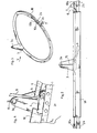
- This device comprises a support belt 1 made of synthetic material, of flexibility and length adapted to go around the waist of the person targeted. At its ends, this support belt is provided with attachment means 2a and 2b of the conventional type, allowing an adjustment of length.
- This plate 3 may in particular have a triangular shape as shown, so as to be firmly fixed by its base on the belt and to extend in the plane of the latter.
- the base of the plate is interposed between the support belt and the person's back, which guarantees that the person is held flat against the back.
- the plate 3 has on its upper portion an attachment hole 3a. Its height is such that this hole is located above the level of the center of gravity G of the person when the device is in place. According to people, a height approximately between 10 and 20 cm is suitable, in particular a height of the order of 15 cm for an adult of normal build and size.
- a small bottle 4 of carbon dioxide under pressure is fixed, equipped with a conventional valve 5 for opening.
- This valve comprises a perforator which can be brought to perforate a sealing cap for the bottle, by tilting a hinged finger at the edge thereof.
- This finger is linked to a control cord 6 which runs along the support belt and is equipped at the front thereof with a handle 7 for ventral maneuvering.
- the valve 5 is connected with a flexible conduit 8 and puts the bottle 4 in communication with the latter when it is actuated.
- the organs of this perfectly conventional valve have not been shown in the figures.
- the device comprises a closed tubular portion, couple 9 which is connected to the flexible conduit 8.
- This tubular portion extends parallel to the support belt 1 and comprises at its ends elastic fastening means 10a and 10b, constituted in particular by elastic sections carrying traditional fastening members.
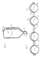
- the length of the tubular portion 9 is of the same order as that of the support belt 1. Said portion carries, distributed along its length, four balloons 11, 12, 13, 14, two 11 and 12 arranged in the vicinity of the belt ends to come to the front of the person, and the two others 13 and 14 arranged on either side of the plate 3 to come behind it. Each balloon is fixed to the tubular portion 9 by a mouth such as 11a, by which it communicates with said portion.
- each balloon is separated into two compartments C “C 2 , by a flexible partition such as 11c; one of the balloons is provided with a buccal mouthpiece 11b provided with a non-return valve, which opens into one of the compartments of said balloon (assumed to be deflated in FIGS. 5 and 6); this compartment is in communication with the homologous compartments C ′ 2 ... of the other balloons by the tubular portion 9, which is itself separated in two by a flexible partition 9a in continuity with the partition 11c (FIGS. 5 and 6).
- These balloons can be folded in the deflated state along the tubular portion.
- the tubular portion 9 can in particular be constituted by a flexible non-inflatable conduit, of flat shape in the absence of gas.
- said portion 9 has the sole function of ensuring communication between the conduit 8 and the balloons and therefore between the bottle and said balloons when the cord 6 is actuated.
- the balloons each have a volume in the inflated state of the order of 2 to 2.5 liters so that the total buoyancy volume is of the order of 8 to 10 liters.
- these volumes can be reduced.
- the tubular portion may be constituted by an inflatable pocket of elongated shape, having the dual function, on the one hand, of ensuring the abovementioned communication, on the other hand of acting itself as the volume of buoyancy once inflated; this volume is added to that of the balloons which may be provided with smaller dimensions.
- tubular portion 9 is linked to the support belt 1 by flexible links, in the example three in number, one 15 located at the rear, and the other two 16 and 17 located at the before.
- the flexible dorsal link 15 is in the example a cord connecting the attachment hole 3a of the plate 3 to the median rear part of the tubular portion 9.
- the length of this link is approximately equal to the height of the plate so that the portion 9 can either be folded down to the passive position above the support belt, or come to be placed in the active position at a distance from said support belt of about twice the height of the plate 3.
- Each ventral link 6 or 17 is in the example constituted by a strap connecting the support belt and the tubular portion, of length of the order of twice the height of the plate 3.
- the tubular portion 9 is arranged, in the active state, in a position approximately parallel to the support belt when the links 15, 16 and 17 are stretched upwards.
- the flexible conuit 8 has a length sufficient to preserve the upward movement ability of said tubular portion 9.
- an envelope 18 is fixed along the support belt in order to be able to contain the tubular portion 9 and the balloons 11-14 in the passive state, in the folded position on said belt.
- This envelope is formed by a flexible wall which projects above and below the belt so as to be able to close around the portion 9 and the balloons.
- Closing means such as adhesive pads 19 keep the envelope in the closed state and allow it to open during the expansion of the balloons when the device is triggered.
- the envelope 18 is fixed on the front face of the support belt so as to pass behind the plate 3.
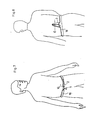
- Figures 5 and 6 show, respectively from the front and back, the device in place in the passive state around the waist of a person.
- the envelope 18 contains the balloons 11-14, the tubular portion 9, the flexible conduit 8 and the control cord 6 which protrudes at the front by the handle 7; the fasteners 2 and 10 of the support belt and of the tubular portion connect the two ends of these elements.
- the bottle and its valve are hidden by the envelope.
- the whole form of the discreet device whose wearing is comfortable and does not bring significant discomfort to the person wearing it.
- the plate 3 rises about fifteen centimeters in the back of the latter, up above its center of gravity G, but is not felt in an annoying way.
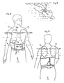
- the inflatable system (tubular portion 9 and balloons 11-14) is then released and is subjected to an upward force in the water.
- This vertical force directed upwards is exerted in the first place on the point of attachment 3a of the plate.
- this force tends to straighten it and to place it in a standing position as shown in FIGS. 8 and 9.
- the balloons In the fully inflated state, the balloons cause the tubular portion 9 to rise along the waist of the wearer (thanks to the elasticity of the fastener 10a, 10b), to the position of FIGS. 8 and 9. In in this position, the wearer is stably held his head above the water, without any risk of tipping.
Landscapes
- Engineering & Computer Science (AREA)
- Mechanical Engineering (AREA)
- Ocean & Marine Engineering (AREA)
- Emergency Lowering Means (AREA)
Claims (15)
Applications Claiming Priority (2)
| Application Number | Priority Date | Filing Date | Title |
|---|---|---|---|
| FR8603954A FR2595654B1 (fr) | 1986-03-13 | 1986-03-13 | Dispositif individuel de sauvetage |
| FR8603954 | 1986-03-13 |
Publications (2)
| Publication Number | Publication Date |
|---|---|
| EP0302059A1 EP0302059A1 (de) | 1989-02-08 |
| EP0302059B1 true EP0302059B1 (de) | 1990-08-16 |
Family
ID=9333313
Family Applications (1)
| Application Number | Title | Priority Date | Filing Date |
|---|---|---|---|
| EP87901514A Expired - Lifetime EP0302059B1 (de) | 1986-03-13 | 1987-03-09 | Persönlicher rettungsgürtel |
Country Status (4)
| Country | Link |
|---|---|
| US (1) | US4925418A (de) |
| EP (1) | EP0302059B1 (de) |
| FR (1) | FR2595654B1 (de) |
| WO (1) | WO1987005578A1 (de) |
Families Citing this family (12)
| Publication number | Priority date | Publication date | Assignee | Title |
|---|---|---|---|---|
| EP0713824A1 (de) * | 1994-11-24 | 1996-05-29 | Dennis Brown | Aufblasbarer Rettungsgürtel |
| US6106348A (en) * | 1996-05-07 | 2000-08-22 | Loisel; Jean | Inflatable personal flotation device |
| WO2000015492A1 (en) * | 1997-05-07 | 2000-03-23 | Jean Loisel | Inflatable personal flotation device with gas inlet nozzle |
| US20040157514A1 (en) * | 2002-11-01 | 2004-08-12 | Courtney William L. | Variably configured inflatable personal flotation device also serving as an emergency distress marker |
| ITMI20040050U1 (it) * | 2004-02-12 | 2004-05-12 | Life Belt S R L | Dispositivo gonfiabile e'emergenza ad attivazione manuale o automatica |
| US7033237B2 (en) * | 2003-05-26 | 2006-04-25 | The Life Belt S.R.L. | Inflatable safety apparatus |
| US20050075473A1 (en) * | 2003-10-07 | 2005-04-07 | Cella James A. | Telechelic emissive oligiomers and polymers derived therefrom |
| US8998667B2 (en) * | 2006-05-23 | 2015-04-07 | Adam J. Malcom | Personal floatation device having selectively inflatable bladders |
| IL210475B (en) * | 2011-01-06 | 2018-03-29 | Muhammad Jabareen | life jacket |
| AT512458B1 (de) * | 2011-12-16 | 2013-12-15 | Giese Fritjof | Rettungsgürtel mit aufblasbaren schwimmkörpern |
| US9371119B2 (en) | 2012-02-22 | 2016-06-21 | Adam J. Malcom | Personal flotation device having selectively inflatable bladders |
| US9033616B2 (en) * | 2013-07-13 | 2015-05-19 | Sean Allen Krumhauer | Personal flotation device for a self contained breathing apparatus |
Family Cites Families (11)
| Publication number | Priority date | Publication date | Assignee | Title |
|---|---|---|---|---|
| US31305A (en) * | 1861-02-05 | Improvement in cultivators | ||
| US1759336A (en) * | 1928-08-28 | 1930-05-20 | Joseph S Wollk | Life-saving swimming belt |
| US2145289A (en) * | 1936-03-24 | 1939-01-31 | Joseph C Barth | Swimming belt |
| US2784426A (en) * | 1953-07-07 | 1957-03-12 | Garrett Corp | Life-saving flotation device |
| US3119132A (en) * | 1962-11-15 | 1964-01-28 | Nayar Isaac Jorge | Life belt |
| GB1419328A (en) * | 1973-04-03 | 1975-12-31 | Freedman R | Article for wear as an inflatable safety device |
| AU462519B2 (en) * | 1973-09-24 | 1975-06-26 | Paul Bardebes David | Improvements in and relating to inflatable buoyant devices |
| FR2466391A1 (fr) * | 1979-10-05 | 1981-04-10 | Krieg Jean Pierre | Dispositif individuel et portatif de securite et de sauvetage en mer |
| US4360351A (en) * | 1979-10-12 | 1982-11-23 | Travinski A Robert | Inflatable safety belt |
| USRE31305E (en) * | 1980-01-28 | 1983-07-12 | Switlik Parachute Company, Inc. | Life preserver of the encapsulated type |
| IT8432819U1 (it) * | 1984-05-22 | 1985-11-22 | Rocco Ajello | Cinghia autogonfiabile con camera d'aria a gobbe di cammello per aerei, sub, windsurf, vela, nautica in genere, bagnanti. |
-
1986
- 1986-03-13 FR FR8603954A patent/FR2595654B1/fr not_active Expired
-
1987
- 1987-03-09 WO PCT/FR1987/000059 patent/WO1987005578A1/fr not_active Ceased
- 1987-03-09 EP EP87901514A patent/EP0302059B1/de not_active Expired - Lifetime
- 1987-03-09 US US07/275,132 patent/US4925418A/en not_active Expired - Fee Related
Also Published As
| Publication number | Publication date |
|---|---|
| EP0302059A1 (de) | 1989-02-08 |
| US4925418A (en) | 1990-05-15 |
| FR2595654A1 (fr) | 1987-09-18 |
| WO1987005578A1 (fr) | 1987-09-24 |
| FR2595654B1 (fr) | 1988-06-24 |
Similar Documents
| Publication | Publication Date | Title |
|---|---|---|
| EP0302059B1 (de) | Persönlicher rettungsgürtel | |
| FR2564798A3 (fr) | Bouee de sauvetage a gonflage automatique | |
| US4813899A (en) | Inflatable pocket life preserver | |
| FR2789651A1 (fr) | Combinaison de glisse aquatique | |
| EP1534092B1 (de) | Sicherheitsvorrichtung vom airbag-typ | |
| FR2578508A1 (fr) | Brassiere de sauvetage gonflable | |
| CA2370052C (fr) | Dispositif pneumatique flottant, notamment radeau pneumatique de survie, equipe de moyens de gonflage a venturi | |
| FR2748941A1 (fr) | Systeme universel de protection totale individuelle contre les accidents et les chutes de grande hauteur | |
| WO1993005831A1 (fr) | Dispositif de transfusion et de perfusion pour goutte a goutte et/ou pour intervention rapide de grande urgence | |
| WO2000038946A1 (fr) | Bandeau appuie-front pour siege de passager | |
| CA3171678A1 (fr) | Gilet de sauvetage pour milieu aquatique | |
| FR2535589A1 (fr) | Sac a dos | |
| FR2565931A1 (fr) | Bouee de sauvetage gonflable en cas de besoin | |
| EP2074019A1 (de) | Aufblasbare auftriebshilfe für schwimmer oder eine andere wassersport betreibende person | |
| FR2543714A1 (fr) | Dispositif a usage individuel pour signalisation en cas de detresse | |
| WO2001097650A1 (fr) | Harnais pivotant pour sac a dos | |
| WO2009016273A2 (fr) | Dispositif de sauvetage formant embarcation | |
| FR2595315A1 (fr) | Gilet de sauvetage gonflable | |
| WO2016016411A1 (fr) | Vessie gonflable pour vetement de flottaison, et vetement de flottaison correspondant | |
| FR2673379A1 (fr) | Bouee de survie pour ensevelissement. | |
| EP0720559B1 (de) | Weste zum schwimmen lernen | |
| WO1985004634A1 (fr) | Dispositif individuel de sauvetage | |
| FR2666297A1 (fr) | Dispositif individuel flottant de survie. | |
| FR2599707A1 (fr) | Vetement de survie en mer | |
| FR2775952A1 (fr) | Perfectionnement pour sellette |
Legal Events
| Date | Code | Title | Description |
|---|---|---|---|
| PUAI | Public reference made under article 153(3) epc to a published international application that has entered the european phase |
Free format text: ORIGINAL CODE: 0009012 |
|
| 17P | Request for examination filed |
Effective date: 19880816 |
|
| AK | Designated contracting states |
Kind code of ref document: A1 Designated state(s): BE CH DE FR GB IT LI |
|
| 17Q | First examination report despatched |
Effective date: 19891228 |
|
| GRAA | (expected) grant |
Free format text: ORIGINAL CODE: 0009210 |
|
| AK | Designated contracting states |
Kind code of ref document: B1 Designated state(s): BE CH DE FR GB IT LI |
|
| REF | Corresponds to: |
Ref document number: 3764367 Country of ref document: DE Date of ref document: 19900920 |
|
| ITF | It: translation for a ep patent filed | ||
| GBT | Gb: translation of ep patent filed (gb section 77(6)(a)/1977) | ||
| PG25 | Lapsed in a contracting state [announced via postgrant information from national office to epo] |
Ref country code: GB Effective date: 19910309 |
|
| PG25 | Lapsed in a contracting state [announced via postgrant information from national office to epo] |
Ref country code: LI Effective date: 19910331 Ref country code: CH Effective date: 19910331 Ref country code: BE Effective date: 19910331 |
|
| PLBE | No opposition filed within time limit |
Free format text: ORIGINAL CODE: 0009261 |
|
| STAA | Information on the status of an ep patent application or granted ep patent |
Free format text: STATUS: NO OPPOSITION FILED WITHIN TIME LIMIT |
|
| 26N | No opposition filed | ||
| BERE | Be: lapsed |
Owner name: MARIOTTO CLAUDE Effective date: 19910331 |
|
| GBPC | Gb: european patent ceased through non-payment of renewal fee | ||
| PG25 | Lapsed in a contracting state [announced via postgrant information from national office to epo] |
Ref country code: FR Effective date: 19911129 |
|
| REG | Reference to a national code |
Ref country code: CH Ref legal event code: PL |
|
| PG25 | Lapsed in a contracting state [announced via postgrant information from national office to epo] |
Ref country code: DE Effective date: 19920101 |
|
| REG | Reference to a national code |
Ref country code: FR Ref legal event code: ST |
|
| PG25 | Lapsed in a contracting state [announced via postgrant information from national office to epo] |
Ref country code: IT Free format text: LAPSE BECAUSE OF NON-PAYMENT OF DUE FEES;WARNING: LAPSES OF ITALIAN PATENTS WITH EFFECTIVE DATE BEFORE 2007 MAY HAVE OCCURRED AT ANY TIME BEFORE 2007. THE CORRECT EFFECTIVE DATE MAY BE DIFFERENT FROM THE ONE RECORDED. Effective date: 20050309 |