EP0301482A2 - Window storing case - Google Patents
Window storing case Download PDFInfo
- Publication number
- EP0301482A2 EP0301482A2 EP88112056A EP88112056A EP0301482A2 EP 0301482 A2 EP0301482 A2 EP 0301482A2 EP 88112056 A EP88112056 A EP 88112056A EP 88112056 A EP88112056 A EP 88112056A EP 0301482 A2 EP0301482 A2 EP 0301482A2
- Authority
- EP
- European Patent Office
- Prior art keywords
- box
- end wall
- window
- viewing
- open front
- Prior art date
- Legal status (The legal status is an assumption and is not a legal conclusion. Google has not performed a legal analysis and makes no representation as to the accuracy of the status listed.)
- Ceased
Links
Images
Classifications
-
- B—PERFORMING OPERATIONS; TRANSPORTING
- B65—CONVEYING; PACKING; STORING; HANDLING THIN OR FILAMENTARY MATERIAL
- B65D—CONTAINERS FOR STORAGE OR TRANSPORT OF ARTICLES OR MATERIALS, e.g. BAGS, BARRELS, BOTTLES, BOXES, CANS, CARTONS, CRATES, DRUMS, JARS, TANKS, HOPPERS, FORWARDING CONTAINERS; ACCESSORIES, CLOSURES, OR FITTINGS THEREFOR; PACKAGING ELEMENTS; PACKAGES
- B65D25/00—Details of other kinds or types of rigid or semi-rigid containers
- B65D25/54—Inspection openings or windows
-
- B—PERFORMING OPERATIONS; TRANSPORTING
- B65—CONVEYING; PACKING; STORING; HANDLING THIN OR FILAMENTARY MATERIAL
- B65D—CONTAINERS FOR STORAGE OR TRANSPORT OF ARTICLES OR MATERIALS, e.g. BAGS, BARRELS, BOTTLES, BOXES, CANS, CARTONS, CRATES, DRUMS, JARS, TANKS, HOPPERS, FORWARDING CONTAINERS; ACCESSORIES, CLOSURES, OR FITTINGS THEREFOR; PACKAGING ELEMENTS; PACKAGES
- B65D21/00—Nestable, stackable or joinable containers; Containers of variable capacity
- B65D21/02—Containers specially shaped, or provided with fittings or attachments, to facilitate nesting, stacking, or joining together
- B65D21/0209—Containers specially shaped, or provided with fittings or attachments, to facilitate nesting, stacking, or joining together stackable or joined together one-upon-the-other in the upright or upside-down position
- B65D21/0213—Containers presenting a continuous stacking profile along the upper or lower edge of at least two opposite side walls
-
- B—PERFORMING OPERATIONS; TRANSPORTING
- B65—CONVEYING; PACKING; STORING; HANDLING THIN OR FILAMENTARY MATERIAL
- B65D—CONTAINERS FOR STORAGE OR TRANSPORT OF ARTICLES OR MATERIALS, e.g. BAGS, BARRELS, BOTTLES, BOXES, CANS, CARTONS, CRATES, DRUMS, JARS, TANKS, HOPPERS, FORWARDING CONTAINERS; ACCESSORIES, CLOSURES, OR FITTINGS THEREFOR; PACKAGING ELEMENTS; PACKAGES
- B65D25/00—Details of other kinds or types of rigid or semi-rigid containers
- B65D25/005—Side walls formed with an aperture or a movable portion arranged to allow removal or insertion of contents
Definitions
- the invention relates to a face storage box with a circumferential stiffening profile, which forms an upper stacking edge and has a viewing opening into which a hinged viewing window can be inserted, the viewing window being pivotable about a pivot which is mounted in a recess for folding down.
- a storage box is known from DE-OS 29 15 812.
- the known storage box has a hollow chamber profile on its end wall, which surrounds the viewing opening on three sides.
- the hollow chamber profile merges at the upper peripheral edge of the box into a stacking edge with a horizontal stacking edge and an upward-facing vertical boundary edge.
- a face storage box with a hollow chamber profile drawn around the entire box, but without an upwardly facing boundary edge, is known from DE-OS 30 14 387.
- a viewing window can be inserted into the viewing opening of the box of the first-mentioned DE-OS 29 15 812.
- the edges of the viewing opening are provided with retaining grooves and webs.
- the known lens has an angled forward leg, on which pivot pins projecting sideways are formed. The spin reach behind bars that protrude into the viewing opening.
- the visor can be released from the holding grooves by lifting and then folded down around the pivot pin to the front. When folded down, the visor hangs more or less freely in front of the box front wall.
- the object of the invention is to design the open fronted storage box so that, in particular when using compartments, simple handling, secured against loss and destruction, is also possible with mechanical devices.
- the visor lies flush against the end wall of the box in the folded state, and that in the region of the pivot, the visor has a recess which, when the visor is in a position relative to the end wall of the box, of exactly 90 degrees, and only in this position, the insertion and removal of the pivot pin in or out of the recess by lateral displacement from the central position to the viewing opening.
- the open front storage box according to the invention has the advantage that the viewing window forms a unit with the box and does not hinder manual or mechanical gripping of the box neither in the folded-up state nor in the folded-down state, since in any case it lies flush against the box and cannot be lost connected is. Handling is therefore independent of whether the lens is folded down or not. When the window is folded down, it can no longer break because it is supported flatly on the front of the box.
- the lens preferably has an extension which, when folded down, engages under the front edge on the front wall of the box and forms a recessed grip. This supports the safe gripping and lifting of the box even when the viewing window is folded down.
- an additional equipment of the storage box with a dust cover contributes to safe handling, in particular by mechanical gripping devices, an embodiment in which the dust cover has two upwardly bent tabs on its back, which can be snapped into openings in the rear stacking edge of the box, so that the dust cover just as the lens can be placed captively, the upwardly bent tabs have a hinge effect, so that the dust cover is held on the box even when open.
- a compartment divider can also be used in the open front storage box according to the invention, which can be inserted between strips in the box, the compartment divider advantageously having wide flanges at least on its edges abutting the walls of the open front storage box. This does not affect the good handling of the box, since the compartment divider with its wide edges is supported on the walls of the box and cannot slip. To define the compartment divider, only slightly bulky strips on the inside of the box are required, which do not interfere and which cannot clog with small parts or dirt.
- the storage bin according to the invention thus has a along the upper edge around the entire box and in particular around the hollow chamber profile pulled around the viewing opening.
- Captive lenses, labels and dust covers as well as non-slipping compartment dividers contribute to safe, in particular mechanical handling.
- the lens forms a unit with the box in such a way that the box can also be lifted when the lens is folded down.
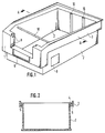
- Fig. 1 shows the storage box in an overall view.
- the box made of plastic has at its upper edge a circumferential hollow chamber profile, the outer walls of which are drawn relatively far downward in the area of the end wall 1 and around a viewing opening. Sufficient free space remains, however, up to the lower edge of the box, so that for handling the box, one can reach into the hollow chambers of the end wall which are open from below and are designed as a recessed grip.
- the downward-drawn hollow chamber profile continues around the front corners of the box and merges into narrower sections on the longitudinal sides 2 of the box.
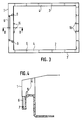
- the hollow chamber profile adjoins the side walls 2 or the rear wall of the box at right angles, horizontal sections 4 (FIG. 2) and, in turn, adjoining them, extending upwards and downwards Flanges 3, which run parallel to the corresponding side wall or rear wall.
- the part of the flange 3 which extends upwards forms a stacking edge together with the section 4 and the part which extends downwards forms the actual hollow chamber profile.
- This downwardly extending part of the flange 3 is connected to the wall 2 by webs 5 (FIGS. 2, 3) running perpendicular to the wall 2.
- the free lower edges of the webs 5 are curved upwards or concavely in order to make it easier to pick up the box on the side walls with mechanical gripping devices acting on the webs.
- the lower edge of the box can additionally be provided with a stacking edge which interacts with the upper stacking edge when the boxes are placed on top of one another and which reinforces the lower edge.
- a label field is arranged in the end wall 1 of the box, which has a groove 6 (FIGS. 1, 4) running around on three sides, into which a label card or the like can be inserted from above, from the side of the viewing opening .
- the lower groove has an inwardly directed nose 7. The label is held particularly securely by the nose 7 when the label is placed in a transparent envelope which is folded once so that the fold can be pushed under the nose 7.
- markings 8 can additionally be made, which always facilitate the arrangement of machine-readable coding fields in the same place on the box, so that it is ensured that e.g. Optical identifiers can also be read automatically and a rotation of the box (turned upside down) can also be automatically recognized.
- These markings 8 can consist of elevations, depressions or the like formed on the walls.
- cavities of the hollow chamber profile can also be designed such that active coding elements can be inserted therein and fastened, for example, by snapping in, which interact with an automatic storage system for the automatic detection of the boxes.
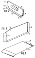
- Recesses 9 are arranged in the lateral boundary of the viewing opening of the box and accommodate corresponding locking and pivot pins 11 of a viewing window 10 (FIG. 5).
- the recesses 9 and the pin 11 cooperate so that the lens can only be mounted on the box in such a position that does not normally occur during operation, so that the lens is captively connected to the box.
- the lens 10 is provided with an angled leg 12 on which the lower pivot 11 are arranged. In the area of these pivots, the lens or the leg 12 has a shoulder or a recess 12a which, when the lens is in a position of exactly 90 ° to the front of the box, and only in this position, the insertion and removal of the lower pivot 11 in the lower recesses 9 of the viewing opening allowed.
- the recess 12a has the shape of an incision with 90 ° side walls, in which a web-shaped section of the end wall 1 can engage in the region of one of the recesses 9 in the case of a lateral movement only in the 90 ° position mentioned.
- the incision and the wall section are tilted against each other and cannot interlock, that is, the viewing window is fixed laterally.
- the visor 10 can be folded down in the assembled state by lifting and rotating about the pivot pin 11, with the angled leg 12 on the visor on which the pivot pins are arranged ensures that they are flush with the front of the folded-down state Front wall 1 of the box rests and forms a unit with it.
- the lens 10 has an extension 13 which, when the lens is folded down, engages under the lower edge of the front of the front wall 1.
- the approach 13 is hollow so that it forms a recessed grip when the lens is folded down. When lifting the box on this recessed grip of the lens, this is secured by the interaction of the approach 13 and the lower edge of the front of the end wall 1, so that the box can be lifted manually and mechanically on the lens recessed grip.
- the lens does not interfere with the handling of the box even when it is folded down.
- compartment dividers 14 For dividing the box in the longitudinal or transverse direction (usually a division in the longitudinal direction is provided) compartment dividers 14 (FIG. 6) can be used. These compartment dividers 14 are provided on the edges or narrow sides with which they rest on the walls of the box, and possibly also on the narrow side lying against the bottom of the box with relatively wide flanges 15 which are supported on the box walls. The flanges 15 form an angle of slightly more than 90 ° on both sides with the plane of the compartment divider, so that a flat "V" is formed. In the event of a bending load, the flanges 15 are supported on the side opposite the bending load against the box walls. The compartment dividers 14 are fixed in the box 15 by means of low strips 16 on the inside of the walls of the box.
- the top of the box can be covered with a dust cover 17 (FIG. 7).
- the dust cover 17 lies on the upper stack edge of the box and has on the back two tabs 19 which are bent upwards at an angle of approximately 30 ° and which engage in corresponding openings in the rear stack edge of the box.
- the dust cover can thus only be inserted and removed in an inclined position of approximately this 30 °, so that the dust cover is also captively attached to the box.
- the dust cover 17 closes the box completely.
- the box can be provided with a support rod 18 (Fig. 1), which consists of a steel tube.
- a spring is arranged in the steel tube between two outwardly projecting plastic mandrels.
Abstract
Description
Die Erfindung betrifft einen Sichtlagerkasten mit einem umlaufenden Versteifungsprofil, das einen oberen Stapelrand bildet und eine Sichtöffnung aufweist, in die eine abklappbare Sichtscheibe einsetzbar ist, wobei die Sichtscheibe zum Abklappen um einen Drehzapfen schwenkbar ist, der in einer Aussparung gelagert ist. Ein solcher Sichtlagerkasten ist aus der DE-OS 29 15 812 bekannt.The invention relates to a face storage box with a circumferential stiffening profile, which forms an upper stacking edge and has a viewing opening into which a hinged viewing window can be inserted, the viewing window being pivotable about a pivot which is mounted in a recess for folding down. Such a storage box is known from DE-OS 29 15 812.
Der bekannte Sichtlagerkasten weist an seiner Stirnwand ein Hohlkammerprofil auf, das die Sichtöffnung an drei Seiten umgibt. Das Hohlkammerprofil geht am oberen umlaufenden Rand des Kastens in einen Stapelrand mit einer horizontalen Stapelkante und einem nach oben weisenden vertikalen Begrenzungsrand über.The known storage box has a hollow chamber profile on its end wall, which surrounds the viewing opening on three sides. The hollow chamber profile merges at the upper peripheral edge of the box into a stacking edge with a horizontal stacking edge and an upward-facing vertical boundary edge.
Ein Sichtlagerkasten mit einem um den ganzen Kasten herumgezogenen Hohlkammerprofil, jedoch ohne nach oben weisenden Begrenzungsrand, ist aus der DE-OS 30 14 387 bekannt.A face storage box with a hollow chamber profile drawn around the entire box, but without an upwardly facing boundary edge, is known from DE-OS 30 14 387.
In die Sichtöffnung des Kastens der erstgenannten DE-OS 29 15 812 kann eine Sichtscheibe eingesetzt werden. Dazu sind die Ränder der Sichtöffnung mit Haltenuten und Stegen versehen. An ihrem unteren Ende hat die bekannte Sichtscheibe einen nach vorne abgewinkelten Schenkel, an den seitwärts vorstehende Drehzapfen angeformt sind. Die Dreh zapfen hintergreifen Stege, die in die Sichtöffnung ragen. Durch Anheben kann die Sichtscheibe aus den Haltenuten ausgeklinkt und anschließend um die Drehzapfen nach vorne abgeklappt werden. Im abgeklappten Zustand hängt die Sichtscheibe mehr oder weniger frei pendelnd vor der Kastenstirnwand.A viewing window can be inserted into the viewing opening of the box of the first-mentioned DE-OS 29 15 812. For this purpose, the edges of the viewing opening are provided with retaining grooves and webs. At its lower end, the known lens has an angled forward leg, on which pivot pins projecting sideways are formed. The spin reach behind bars that protrude into the viewing opening. The visor can be released from the holding grooves by lifting and then folded down around the pivot pin to the front. When folded down, the visor hangs more or less freely in front of the box front wall.
Diese Anordnung hat den Nachteil, nicht sicher gehandhabt werden zu können, insbesondere nicht mit mechanischen Einrichtungen. So kann die Sichtscheibe bereits bei manueller Handhabung des Kastens versehentlich leicht aus ihrer geschlossenen Stellung in die geöffnete Stellung geraten. Bei einem Transport des Kastens durch mechanische Einrichtungen kann ein unbeabsichtigtes Abklappen der Sichtscheibe durch die dabei unvermeidlichen Erschütterungen erfolgen. Dies hat einige unerwünschte Folgen: Zum einen kann neben Teilen des Kasteninhalts auch die Sichtscheibe selbst verlorengehen. Eine entsprechende Sicherung der Sichtscheibe ist zwar durch in Öffnungen des bekannten Kastens einsetzbare Stopfen möglich, solche zusätzlichen Sicherungselemente neigen jedoch erfahrungsgemäß dazu, bei Bedarf nicht vorhanden zu sein. Bei einem Transport des Kastens etwa auf einer geneigten Rollenbahn, wobei die Kästen mit erheblicher Wucht aufeinanderprallen können, werden abgeklappte Sichtscheiben leicht zerstört, wobei scharfkantige Splitter entstehen, die eine erhebliche Gefahr darstellen. Vor allem aber verhindert eine abgeklappte Sichtscheibe ein sicheres manuelles oder mechanisches Ergreifen und Hochheben des Kastens, da sie von der Frontseite des bekannten Kastens absteht.This arrangement has the disadvantage that it cannot be handled safely, especially not with mechanical devices. This means that even with manual handling of the box, the lens can easily accidentally move from its closed position into the open position. When the box is transported through mechanical devices, the lens can be unintentionally folded down due to the inevitable vibrations. This has some undesirable consequences: First, in addition to parts of the contents of the box, the viewing window itself can also be lost. Appropriate securing of the viewing window is possible by means of plugs which can be inserted into openings in the known box, but experience has shown that such additional securing elements tend not to be present if required. When the box is transported, for example on an inclined roller conveyor, the boxes being able to collide with considerable force, the viewing panes are easily destroyed, resulting in sharp-edged splinters which represent a considerable danger. Above all, however, a folded down viewing window prevents safe manual or mechanical gripping and lifting of the box, since it protrudes from the front of the known box.
Darüberhinaus läßt sich der bekannte Sichtlagerkasten wegen dieser Sicherheitsmängel schlecht mit Gefachen und zusätzlichen Elementen versehen, da diese weitere Unsicherheitsfaktoren bei der Handhabung der Sichtscheibe darstellen.In addition, the known face storage box is difficult to provide with compartments and additional elements because of these safety deficiencies, since these represent further uncertainty factors when handling the faceplate.
Aufgabe der Erfindung ist es, den eingangs beschriebenen Sichtlagerkasten so auszubilden, daß insbesondere bei der Verwendung von Gefachen eine einfache, gegen Verlust und Zerstörung gesicherte Handhabung auch mit mechanischen Einrichtungen möglich ist.The object of the invention is to design the open fronted storage box so that, in particular when using compartments, simple handling, secured against loss and destruction, is also possible with mechanical devices.
Diese Aufgabe wird erfindungsgemäß dadurch gelöst, daß die Sichtscheibe im abgeklappten Zustand bündig an der Stirnwand des Kastens anliegt, und daß im Bereich des Drehzapfens die Sichtscheibe eine Ausnehmung aufweist, die bei einer Stellung der Sichtscheibe zur Stirnwand des Kastens von exakt 90 Grad, und nur in dieser Stellung, das Einsetzen und Herausnehmen des Drehzapfens in die bzw. aus der Aussparung durch seitliches Verschieben aus der zur Sichtöffnung mittigen Position ermöglicht.This object is achieved in that the visor lies flush against the end wall of the box in the folded state, and that in the region of the pivot, the visor has a recess which, when the visor is in a position relative to the end wall of the box, of exactly 90 degrees, and only in this position, the insertion and removal of the pivot pin in or out of the recess by lateral displacement from the central position to the viewing opening.
Der erfindungsgemäße Sichtlagerkasten hat den Vorteil, daß die Sichtscheibe mit dem Kasten eine Einheit bildet und weder im nach oben geklappten Zustand noch im nach unten geklappten Zustand das manuelle oder mechanische Ergreifen des Kastens behindert, da sie in jedem Fall bündig am Kasten anliegt und unverlierbar damit verbunden ist. Die Handhabung ist somit unabhängig davon, ob die Sichtscheibe abgeklappt ist oder nicht. Die Sichtscheibe kann im abgeklappten Zustand nicht mehr zu Bruch gehen, da sie sich flächig an der Stirnseite des Kastens abstützt.The open front storage box according to the invention has the advantage that the viewing window forms a unit with the box and does not hinder manual or mechanical gripping of the box neither in the folded-up state nor in the folded-down state, since in any case it lies flush against the box and cannot be lost connected is. Handling is therefore independent of whether the lens is folded down or not. When the window is folded down, it can no longer break because it is supported flatly on the front of the box.
Die Sichtscheibe weist bevorzugt einen Ansatz auf, der im abgeklappten Zustand unter die Vorderkante an der Stirnwand des Kastens greift und eine Griffmulde bildet. Dadurch wird das sichere Ergreifen und Hochheben des Kastens auch an einer heruntergeklappten Sichtscheibe unterstützt.The lens preferably has an extension which, when folded down, engages under the front edge on the front wall of the box and forms a recessed grip. This supports the safe gripping and lifting of the box even when the viewing window is folded down.
Bei einer zusätzlichen Ausrüstung des Sichtlagerkastens mit einem Staubdeckel trägt zur sicheren Handhabung insbesondere durch mechanische Greifeinrichtungen eine Ausgestaltung bei, in der der Staubdeckel an seiner Rückseite zwei nach oben gebogene Laschen aufweist, die in Öffnungen im rückwärtigen Stapelrand des Kastens einrastbar sind, so daß der Staubdeckel ebenso wie die Sichtscheibe unverlierbar aufgesetzt werden kann, wobei die nach oben gebogenen Laschen einen Scharniereffekt haben, so daß der Staubdeckel auch im aufgeklappten Zustand am Kasten gehalten ist.With an additional equipment of the storage box with a dust cover contributes to safe handling, in particular by mechanical gripping devices, an embodiment in which the dust cover has two upwardly bent tabs on its back, which can be snapped into openings in the rear stacking edge of the box, so that the dust cover just as the lens can be placed captively, the upwardly bent tabs have a hinge effect, so that the dust cover is held on the box even when open.
Es kann bei dem erfindungsgemäßen Sichtlagerkasten auch ein Fachteiler verwendet werden, der zwischen Leisten im Kasten einsetzbar ist, wobei der Fachteiler vorteilhaft wenigstens an seinen an den Wänden des Sichtlagerkastens anliegenden Rändern breite Flansche aufweist. Dadurch wird die gute Handhabung des Kasten nicht beeinträchtigt, da sich der Fachteiler mit seinen breiten Rändern an den Wänden des Kastens abstützt und nicht verrutschen kann. Zur Festlegung des Fachteilers sind dabei nur mehr schwach auftragende Leisten an den Kasteninnenwänden erforderlich, die nicht stören und die sich nicht mit Kleinteilen oder Schmutz zusetzen können.A compartment divider can also be used in the open front storage box according to the invention, which can be inserted between strips in the box, the compartment divider advantageously having wide flanges at least on its edges abutting the walls of the open front storage box. This does not affect the good handling of the box, since the compartment divider with its wide edges is supported on the walls of the box and cannot slip. To define the compartment divider, only slightly bulky strips on the inside of the box are required, which do not interfere and which cannot clog with small parts or dirt.
Die Ausbildung mit einer Etikettenhalterung mit Nuten an der Stirnwand, wobei vorteilhaft die Nuten eine Nase zum Festhalten der Etiketten aufweisen, trägt schließlich dazu bei, daß auch Etiketten unverlierbar am Kasten angebracht werden können, so daß Störungen durch fehlende oder halb aus ihren Halterungen herausgesprungene Etikettenschilder vermieden werden.The training with a label holder with grooves on the end wall, the grooves advantageously having a nose for holding the labels, ultimately contributes to the fact that labels can also be captively attached to the box, so that faults due to missing label labels or half-jumped out of their holders be avoided.
Der erfindungsgemäße Sichtlagerkasten weist somit ein längs des oberen Randes um den ganzen Kasten und insbesondere um die Sichtöffnung herumgezogenes Hohlkammerprofil auf. Zur sicheren, insbesondere mechanischen Handhabung tragen unverlierbare Sichtscheiben, Etiketten und Staubdeckel sowie nicht verrutschende Fachteiler bei. Die Sichtscheibe bildet mit dem Kasten derart eine Einheit, daß der Kasten auch an einer abgeklappten Sichtscheibe hochgehoben werden kann.The storage bin according to the invention thus has a along the upper edge around the entire box and in particular around the hollow chamber profile pulled around the viewing opening. Captive lenses, labels and dust covers as well as non-slipping compartment dividers contribute to safe, in particular mechanical handling. The lens forms a unit with the box in such a way that the box can also be lifted when the lens is folded down.
Ein Ausführungsbeispiel des erfindungsgemäßen Sichtlagerkastens wird im folgenden anhand der Zeichnung näher erläutert. Es zeigen:
- Fig. 1 eine perspektivische Gesamtansicht eines Sichtlagerkastens;
- Fig. 2 einen Querschnitt längs A - A in Fig. 1;
- Fig. 3 eine Aufsicht auf den Sichtlagerkasten;
- Fig. 4 einen Querschnitt längs B - B in Fig. 3;
- Fig. 5 eine Sichtscheibe für den Sichtlagerkasten;
- Fig. 6 einen Fachteiler für den Sichtlagerkasten; und
- Fig. 7 einen Staubdeckel für den Sichtlagerkasten.
- Figure 1 is an overall perspective view of a storage bin.
- FIG. 2 shows a cross section along A - A in FIG. 1;
- Figure 3 is a plan view of the storage box.
- FIG. 4 shows a cross section along BB in FIG. 3;
- 5 shows a viewing window for the storage box;
- 6 shows a compartment divider for the open storage bin; and
- Fig. 7 is a dust cover for the storage bin.
Die Fig. 1 zeigt den Sichtlagerkasten in einer Gesamtansicht. Der aus Kunststoff bestehende Kasten weist an seinem oberen Rand ein umlaufendes Hohlkammerprofil auf, dessen äußere Wände im Bereich der Stirnwand 1 und um eine Sichtöffnung herum relativ weit nach unten gezogen sind. Bis zum unteren Rand des Kastens verbleibt jedoch genügend freier Raum, so daß zur Handhabung des Kastens in die von unten offenen, als Griffmulde ausgebildeten Hohlkammern der Stirnwand gegriffen werden kann. Das nach unten gezogene Hohlkammerprofil setzt sich um die vorderen Ecken des Kastens herum fort und geht an den Längsseiten 2 des Kastens in schmalere Abschnitte über.Fig. 1 shows the storage box in an overall view. The box made of plastic has at its upper edge a circumferential hollow chamber profile, the outer walls of which are drawn relatively far downward in the area of the end wall 1 and around a viewing opening. Sufficient free space remains, however, up to the lower edge of the box, so that for handling the box, one can reach into the hollow chambers of the end wall which are open from below and are designed as a recessed grip. The downward-drawn hollow chamber profile continues around the front corners of the box and merges into narrower sections on the longitudinal sides 2 of the box.
An den Längsseiten und ebenso an der Rückseite des Kastens weist das Hohlkammerprofil sich an die Seitenwände 2 bzw. an die Rückwand des Kasten im rechten Winkel anschließende, horizontale Abschnitte 4 (Fig. 2) und daran sich wiederum anschließende, davon nach oben und unten erstreckende Flansche 3 auf, die parallel zur entsprechenden Seitenwand bzw. Rückwand verlaufen. Der sich nach oben erstreckende Teil des Flansches 3 bildet zusammen mit dem Abschnitt 4 einen Stapelrand und der sich nach unten erstreckende Teil das eigentliche Hohlkammerprofil. Dieser sich nach unten erstreckende Teil des Flansches 3 ist durch senkrecht zur Wand 2 verlaufende Stege 5 (Fig. 2, 3) mit der Wand 2 verbunden. Die freien unteren Ränder der Stege 5 sind nach oben bzw. konkav gewölbt, um das Aufnehmen das Kastens an den Seitenwänden mit an den Stegen angreifenden mechanischen Greifeinrichtungen zu erleichtern.On the long sides and also on the back of the box, the hollow chamber profile adjoins the side walls 2 or the rear wall of the box at right angles, horizontal sections 4 (FIG. 2) and, in turn, adjoining them, extending upwards and downwards Flanges 3, which run parallel to the corresponding side wall or rear wall. The part of the flange 3 which extends upwards forms a stacking edge together with the section 4 and the part which extends downwards forms the actual hollow chamber profile. This downwardly extending part of the flange 3 is connected to the wall 2 by webs 5 (FIGS. 2, 3) running perpendicular to the wall 2. The free lower edges of the
Der untere Rand des Kastens kann zusätzlich mit einer Stapelkante versehen sein, die beim Aufeinandersetzen der Kästen mit dem oberen Stapelrand zusammenwirkt und die den unteren Rand verstärkt.The lower edge of the box can additionally be provided with a stacking edge which interacts with the upper stacking edge when the boxes are placed on top of one another and which reinforces the lower edge.
Unterhalb der Sichtöffnung ist in der Stirnwand 1 des Kastens ein Etikettenfeld angeordnet, das eine an drei Seiten umlaufende Nut 6 (Fig. 1, 4) aufweist, in die von oben, von der Seite der Sichtöffnung her, eine Etikettenkarte oder dergleichen eingesteckt werden kann. Um die Etikette auch bei gekipptem Kasten unverlierbar festzuhalten, weist die untere Nut eine nach innen gerichtete Nase 7 auf. Besonders sicher wird die Etikette von der Nase 7 gehalten, wenn die Etikette in eine durchsichtige Hülle gegeben wird, die einmal so gefalzt ist, daß der Falz unter die Nase 7 geschoben werden kann.Below the viewing opening, a label field is arranged in the end wall 1 of the box, which has a groove 6 (FIGS. 1, 4) running around on three sides, into which a label card or the like can be inserted from above, from the side of the viewing opening . In order to hold the label captively even when the box is tilted, the lower groove has an inwardly directed nose 7. The label is held particularly securely by the nose 7 when the label is placed in a transparent envelope which is folded once so that the fold can be pushed under the nose 7.
An den Wänden, z.B. an den Seitenwänden 2 des Kastens können zusätzlich Markierungen 8 (Fig. 1) angebracht sein, die das Anordnen von maschinenlesbaren Kodierungsfeldern immer an der gleichen Stelle des Kastens erleichtern, so daß sichergestellt ist, daß z.B. optische Kennungen auch automatisch gelesen werden können und etwa eine Verdrehung des Kastens (verkehrt herum abgestellt) ebenfalls automatisch erkannt werden kann. Diese Markierungen 8 können aus an den Wänden ausgebildete Erhöhungen, Vertiefungen oder ähnlichem bestehen.On the walls, e.g. On the side walls 2 of the box, markings 8 (FIG. 1) can additionally be made, which always facilitate the arrangement of machine-readable coding fields in the same place on the box, so that it is ensured that e.g. Optical identifiers can also be read automatically and a rotation of the box (turned upside down) can also be automatically recognized. These
Auch können darüberhinaus einige der Hohlräume des Hohlkammerprofils so ausgebildet sein, daß darin aktive Kodierelemente eingeschoben und beispielsweise durch Einrasten befestigt werden können, die mit einem automatischen Lagersystem zur selbsttätigen Erkennung der Kästen zusammenwirken.Furthermore, some of the cavities of the hollow chamber profile can also be designed such that active coding elements can be inserted therein and fastened, for example, by snapping in, which interact with an automatic storage system for the automatic detection of the boxes.
In der seitlichen Begrenzung der Sichtöffnung des Kastens sind Aussparungen 9 angeordnet, die entsprechende Rast- und Drehzapfen 11 einer Sichtscheibe 10 (Fig. 5) aufnehmen. Die Aussparungen 9 und die Zapfen 11 wirken dabei so zusammen, daß die Sichtscheibe nur in einer solchen Position am Kasten montierbar ist, die im Betrieb normalerweise nicht auftritt, so daß die Sichtscheibe unverlierbar mit dem Kasten verbunden ist. Dazu ist die Sichtscheibe 10 mit einem abgewinkelten Schenkel 12 versehen, an dem die unteren Drehzapfen 11 angeordnet sind. Im Bereich dieser Drehzapfen weist die Sichtscheibe bzw. der Schenkel 12 einen Absatz oder eine Ausnehmung 12a auf, die bei einer Stellung der Sichtscheibe zur Frontseite des Kastens von exakt 90°, und nur in dieser Stellung, das Einsetzen und Herausnehmen der unteren Drehzapfen 11 in die unteren Aussparungen 9 der Sichtöffnung erlaubt. In allen anderen Stellungen läßt sich die Sicht scheibe seitlich nicht aus einer zur Sichtöffnung mittigen Position, in der beide der unteren Drehzapfen 11 in den entsprechenden Aussparungen 9 sitzen, verschieben. Dazu hat die Ausnehmung 12a die Form eines Einschnittes mit 90°-Seitenwänden, in den bei einer seitlichen Bewegung nur in der genannten 90°-Stellung ein stegförmiger Abschnitt der Stirnwand 1 im Bereich einer der Aussparungen 9 eingreifen kann. Bei jedem anderen Winkel als 90° sind der Einschnitt und der Wandabschnitt gegeneinander verkantet und können nicht ineinandergreifen, das heißt, die Sichtscheibe liegt seitlich fest.
Die Sichtscheibe 10 kann im montierten Zustand durch Anheben und Drehen um den Drehzapfen 11 nach unten geklappt werden, wobei durch den abgewinkelten Schenkel 12 an der Sichtscheibe, an dem die Drehzapfen angeordnet sind, erreicht wird, daß diese im heruntergeklappten Zustand bündig an der Vorderseite der Stirnwand 1 des Kastens anliegt und mit diesem eine Einheit bildet.The
Die Sichtscheibe 10 weist einen Ansatz 13 auf, der bei heruntergeklappter Sichtscheibe unter die untere Kante der Vorderseite der Stirnwand 1 greift. Der Ansatz 13 ist hohl ausgebildet, so daß er bei heruntergeklappter Sichtscheibe eine Griffmulde bildet. Beim Anheben des Kastens an dieser Griffmulde der Sichtscheibe wird diese durch das Zusammenwirken des Ansatzes 13 und des unteren Randes der Vorderseite der Stirnwand 1 gesichert, so daß der Kasten manuell und maschinell auch an der Sichtscheiben-Griffmulde hochgehoben werden kann. Die Sichtscheibe stört somit auch im heruntergeklappten Zustand die Handhabung des Kastens nicht.The
Zur Unterteilung des Kastens in Längs- oder Querrichtung (meist ist eine Unterteilung in Längsrichtung vorgesehen) können Fachteiler 14 (Fig. 6) eingesetzt werden. Diese Fachteiler 14 sind an den Rändern oder Schmalseiten, mit denen sie an den Wänden des Kastens anliegen, und evtl. auch noch an der am Boden des Kastens anliegenden Schmalseite mit relativ breiten Flanschen 15 versehen, die sich an den Kastenwänden abstützen. Die Flansche 15 schließen nach beiden Seiten mit der Ebene des Fachteilers einen Winkel von etwas mehr als 90° ein, so daß ein flaches "V" gebildet wird. Bei einer Biegebelastung stützen sich die Flansche 15 auf der der Biegelast gegenüberliegenden Seite gegen die Kastenwände ab. Die Fixierung der Fachteiler 14 im Kasten 15 erfolgt durch niedrige Leisten 16 an den Innenseiten der Wände des Kastens.For dividing the box in the longitudinal or transverse direction (usually a division in the longitudinal direction is provided) compartment dividers 14 (FIG. 6) can be used. These
Der Kasten kann an der Oberseite mit einem Staubdeckel 17 (Fig. 7) abgedeckt werden. Der Staubdeckel 17 liegt am oberen Stapelrand des Kastens auf und weist auf der Rückseite zwei Laschen 19 auf, die um einem Winkel von etwa 30° nach oben gebogen sind und die in entsprechende Öffnungen im rückwärtigen Stapelrand des Kastens eingreifen. Der Staubdeckel kann somit nur in einer Schräglage von etwa diesen 30° eingesetzt und abgenommen werden, so daß auch der Staubdeckel unverlierbar am Kasten angebracht ist. In Verbindung mit der Sichtscheibe 10 schließt der Staubdeckel 17 den Kasten vollständig ab.The top of the box can be covered with a dust cover 17 (FIG. 7). The
Schließlich kann der Kasten noch mit einer Tragestange 18 (Fig. 1) versehen werden, die aus einem Stahlrohr besteht. In dem Stahlrohr ist zwischen zwei nach außen vorstehenden Kunststoffdornen eine Feder angeordnet. In den Wänden des Kastens befinden sich Öffnungen, in die die Kunststoffdorne der Tragestange eingreifen können. Zum Einbau werden die Kunststoffdorne in das Stahlrohr gedrückt und es wird die Tragestange einfach in die Öffnungen eingerastet.Finally, the box can be provided with a support rod 18 (Fig. 1), which consists of a steel tube. A spring is arranged in the steel tube between two outwardly projecting plastic mandrels. There are openings in the walls of the box, into which the plastic pins of the carrying bar can engage. For installation, the plastic mandrels are pressed into the steel tube and the support rod is simply snapped into the openings.
Claims (5)
- umlaufenden Versteifungsprofil, das einen oberen Stapelrand bildet und eine Sichtöffnung aufweist, in die eine abklappbare Sichtscheibe (10) einsetzbar ist,
-- wobei die Sichtscheibe (10) zum Abklappen um einen Drehzapfen (11) schwenkbar ist, der in einer Aussparung (9) gelagert ist,
dadurch gekennzeichnet, daß
- die Sichtscheibe (10) im abgeklappten Zustand bündig an der Stirnwand (1) des Kastens anliegt, und daß
- im Bereich des Drehzapfens (11) die Sichtscheibe eine Ausnehmung (12a) aufweist, die bei einer Stellung der Sichtscheibe (10) zur Stirnwand (1) des Kastens von exakt 90 Grad, und nur in dieser Stellung, das Einsetzen und Herausnehmen des Drehzapfens (11) in die bzw. aus der Aussparung (9) durch seitliches Verschieben aus der zur Sichtöffnung mittigen Position ermöglicht.1. Open fronted storage box with one
- All-round stiffening profile which forms an upper stack edge and has a viewing opening into which a hinged viewing window (10) can be inserted,
- The viewing pane (10) can be pivoted about a pivot (11) which is mounted in a recess (9),
characterized in that
- The lens (10) lies flush against the end wall (1) of the box in the folded state, and that
- In the region of the pivot pin (11), the viewing window has a recess (12a) which, when the viewing window (10) is in relation to the end wall (1) of the box, of exactly 90 degrees, and only in this position, the insertion and removal of the pivot pin (11) in or out of the recess (9) by lateral displacement from the central position to the viewing opening.
Applications Claiming Priority (2)
| Application Number | Priority Date | Filing Date | Title |
|---|---|---|---|
| DE3724828 | 1987-07-27 | ||
| DE19873724828 DE3724828C1 (en) | 1987-07-27 | 1987-07-27 | Open fronted storage bin |
Publications (2)
| Publication Number | Publication Date |
|---|---|
| EP0301482A2 true EP0301482A2 (en) | 1989-02-01 |
| EP0301482A3 EP0301482A3 (en) | 1990-01-31 |
Family
ID=6332444
Family Applications (1)
| Application Number | Title | Priority Date | Filing Date |
|---|---|---|---|
| EP88112056A Ceased EP0301482A3 (en) | 1987-07-27 | 1988-07-26 | Window storing case |
Country Status (2)
| Country | Link |
|---|---|
| EP (1) | EP0301482A3 (en) |
| DE (1) | DE3724828C1 (en) |
Cited By (5)
| Publication number | Priority date | Publication date | Assignee | Title |
|---|---|---|---|---|
| EP0484718A1 (en) * | 1990-11-07 | 1992-05-13 | Fritz Schäfer Gesellschaft mit beschränkter Haftung | Stackable metal bin |
| EP0549991A2 (en) * | 1991-12-30 | 1993-07-07 | Repsol-Butano, S.A. | Closing device for skeleton boxes for transporting liquefied gas bottles |
| EP0480994B1 (en) * | 1989-07-03 | 1995-02-15 | Torbjörn KARLSEN | Apparatus and the use thereof for handling of stackable boxes |
| CN109809050A (en) * | 2019-04-04 | 2019-05-28 | 贵州师范大学 | It is a kind of for storing the body structure of paleontological fossil sample |
| DE202021103124U1 (en) | 2021-06-09 | 2021-06-17 | POS TUNING Udo Voßhenrich GmbH & Co. KG | Device for the presentation of goods |
Families Citing this family (3)
| Publication number | Priority date | Publication date | Assignee | Title |
|---|---|---|---|---|
| DE8900310U1 (en) * | 1989-01-12 | 1989-03-09 | Bito-Lagertechnik Bittmann Gmbh, 6580 Idar-Oberstein, De | |
| DE19809394C2 (en) * | 1998-03-05 | 2002-01-17 | Sanacorp Pharmahandel Ag | Stackable storage arrangement box |
| DE102006017578B4 (en) * | 2006-04-13 | 2014-02-27 | Bito-Lagertechnik Bittmann Gmbh | Partitioning device for dividing the interior of a container |
Citations (3)
| Publication number | Priority date | Publication date | Assignee | Title |
|---|---|---|---|---|
| FR1401306A (en) * | 1964-04-20 | 1965-06-04 | Method and device for packaging articles in stackable storage bins | |
| US3259269A (en) * | 1965-05-10 | 1966-07-05 | Shell Oil Co | Stackable bin container |
| FR2556321A1 (en) * | 1983-12-09 | 1985-06-14 | Utz Ag Georg | Stackable container for storage and transport made of synthetic material |
Family Cites Families (5)
| Publication number | Priority date | Publication date | Assignee | Title |
|---|---|---|---|---|
| GB187882A (en) * | 1921-12-09 | 1922-11-02 | Bertram Thomas | Improvements in boxes |
| DE2915812C2 (en) * | 1979-04-19 | 1986-05-15 | Fritz Schäfer GmbH, 5908 Neunkirchen | Stackable plastic transport and storage box |
| DE2937666A1 (en) * | 1979-09-18 | 1981-04-02 | Fritz Schäfer GmbH Fabriken für Lager- und Betriebseinrichtungen, Salchendorf bei Neunkirchen, Kreis Siegen, 5908 Neunkirchen | TRANSPORT AND / OR STORAGE BOX, ESPECIALLY PLASTIC |
| DE3014387A1 (en) * | 1980-04-15 | 1981-10-22 | Fritz Schäfer GmbH Fabriken für Lager- und Betriebseinrichtungen, Salchendorf bei Neunkirchen, Kreis Siegen, 5908 Neunkirchen | STORAGE DISPLAY BOX |
| DE3310874A1 (en) * | 1982-04-19 | 1983-10-27 | Fritz Schäfer GmbH, 5908 Neunkirchen | Stackable transport and visible-storage box of plastic |
-
1987
- 1987-07-27 DE DE19873724828 patent/DE3724828C1/en not_active Expired
-
1988
- 1988-07-26 EP EP88112056A patent/EP0301482A3/en not_active Ceased
Patent Citations (3)
| Publication number | Priority date | Publication date | Assignee | Title |
|---|---|---|---|---|
| FR1401306A (en) * | 1964-04-20 | 1965-06-04 | Method and device for packaging articles in stackable storage bins | |
| US3259269A (en) * | 1965-05-10 | 1966-07-05 | Shell Oil Co | Stackable bin container |
| FR2556321A1 (en) * | 1983-12-09 | 1985-06-14 | Utz Ag Georg | Stackable container for storage and transport made of synthetic material |
Cited By (6)
| Publication number | Priority date | Publication date | Assignee | Title |
|---|---|---|---|---|
| EP0480994B1 (en) * | 1989-07-03 | 1995-02-15 | Torbjörn KARLSEN | Apparatus and the use thereof for handling of stackable boxes |
| EP0484718A1 (en) * | 1990-11-07 | 1992-05-13 | Fritz Schäfer Gesellschaft mit beschränkter Haftung | Stackable metal bin |
| EP0549991A2 (en) * | 1991-12-30 | 1993-07-07 | Repsol-Butano, S.A. | Closing device for skeleton boxes for transporting liquefied gas bottles |
| EP0549991A3 (en) * | 1991-12-30 | 1993-12-08 | Repsol Butano Sa | Closing device for skeleton boxes for transporting liquefied gas bottles |
| CN109809050A (en) * | 2019-04-04 | 2019-05-28 | 贵州师范大学 | It is a kind of for storing the body structure of paleontological fossil sample |
| DE202021103124U1 (en) | 2021-06-09 | 2021-06-17 | POS TUNING Udo Voßhenrich GmbH & Co. KG | Device for the presentation of goods |
Also Published As
| Publication number | Publication date |
|---|---|
| DE3724828C1 (en) | 1989-02-23 |
| EP0301482A3 (en) | 1990-01-31 |
Similar Documents
| Publication | Publication Date | Title |
|---|---|---|
| AT401765B (en) | CONTAINER WITH SWIVELING SIDEWALLS | |
| EP0786412B1 (en) | Transport and storage container | |
| EP0389802A1 (en) | Divisible container, especially a bottle crate | |
| DE3511321A1 (en) | Stackable containers | |
| EP2147867B1 (en) | Storage cabinet | |
| DE3724828C1 (en) | Open fronted storage bin | |
| DE3909352C2 (en) | ||
| EP0236380B1 (en) | Divisible crate for bottles | |
| DE102006012557A1 (en) | Grid repeated use | |
| DE2812052A1 (en) | CONTAINER WITH AN INTERCHANGEABLE TAPE CASSETTE | |
| DE2525169C3 (en) | Plastic bottle crate with locking device | |
| DE102019111950B4 (en) | Stackable storage unit and stacks of storage units | |
| EP0067323B1 (en) | Collapsible crate | |
| EP2500291A1 (en) | Collapsible transport and storage container | |
| EP1160170A2 (en) | Shipping container | |
| DE4109153C2 (en) | Device for storing CD cassettes | |
| DE2701698C3 (en) | Covering device for protecting guideways on machine tools | |
| EP0236514B1 (en) | Plastic transport and storage crate | |
| EP1713696B1 (en) | Storage bin | |
| DE202006004359U1 (en) | Lattice compartment unit for beverage industry, has lug, where width of lug and length and breadth of recess are choosen such that lug is gripped by recess and grips behind wall area of rod adjacent to recess, during flat condition of unit | |
| DE8620396U1 (en) | Cassette for storing elongated objects | |
| DE2645116C2 (en) | ||
| EP0423603B1 (en) | Drawer shelf | |
| EP0367168A1 (en) | Crate for bottles | |
| DE4204464C1 (en) | Magazine for transporting cheque, credit or identification card(s) - has cards stacked in channel section duct with spring loaded latches in side walls as base |
Legal Events
| Date | Code | Title | Description |
|---|---|---|---|
| PUAI | Public reference made under article 153(3) epc to a published international application that has entered the european phase |
Free format text: ORIGINAL CODE: 0009012 |
|
| AK | Designated contracting states |
Kind code of ref document: A2 Designated state(s): ES FR GB IT |
|
| PUAL | Search report despatched |
Free format text: ORIGINAL CODE: 0009013 |
|
| AK | Designated contracting states |
Kind code of ref document: A3 Designated state(s): ES FR GB IT |
|
| 17P | Request for examination filed |
Effective date: 19900514 |
|
| 17Q | First examination report despatched |
Effective date: 19911125 |
|
| STAA | Information on the status of an ep patent application or granted ep patent |
Free format text: STATUS: THE APPLICATION HAS BEEN REFUSED |
|
| 18R | Application refused |
Effective date: 19920806 |