EP0301244A1 - Device for inserting at least one insert in printed products - Google Patents
Device for inserting at least one insert in printed products Download PDFInfo
- Publication number
- EP0301244A1 EP0301244A1 EP88110167A EP88110167A EP0301244A1 EP 0301244 A1 EP0301244 A1 EP 0301244A1 EP 88110167 A EP88110167 A EP 88110167A EP 88110167 A EP88110167 A EP 88110167A EP 0301244 A1 EP0301244 A1 EP 0301244A1
- Authority
- EP
- European Patent Office
- Prior art keywords
- printed products
- clamping
- displacement
- printed
- products
- Prior art date
- Legal status (The legal status is an assumption and is not a legal conclusion. Google has not performed a legal analysis and makes no representation as to the accuracy of the status listed.)
- Granted
Links
Images


Classifications
-
- B—PERFORMING OPERATIONS; TRANSPORTING
- B65—CONVEYING; PACKING; STORING; HANDLING THIN OR FILAMENTARY MATERIAL
- B65H—HANDLING THIN OR FILAMENTARY MATERIAL, e.g. SHEETS, WEBS, CABLES
- B65H39/00—Associating, collating, or gathering articles or webs
- B65H39/02—Associating,collating or gathering articles from several sources
- B65H39/06—Associating,collating or gathering articles from several sources from delivery streams
- B65H39/065—Associating,collating or gathering articles from several sources from delivery streams by collecting in rotary carriers
-
- B—PERFORMING OPERATIONS; TRANSPORTING
- B65—CONVEYING; PACKING; STORING; HANDLING THIN OR FILAMENTARY MATERIAL
- B65H—HANDLING THIN OR FILAMENTARY MATERIAL, e.g. SHEETS, WEBS, CABLES
- B65H2301/00—Handling processes for sheets or webs
- B65H2301/40—Type of handling process
- B65H2301/43—Gathering; Associating; Assembling
- B65H2301/434—In channels, e.g. in which the articles are substantially vertical or inclined
- B65H2301/4341—In channels, e.g. in which the articles are substantially vertical or inclined with several channels on a rotary carrier rotating around an axis parallel to the channels
Definitions
- the present invention relates to a device for inserting at least one insert into printed products, in particular for inserting at least one insert into folded main printing products according to the preamble of claim 1.
- Such a device is known from CH-PS 649 267 and the corresponding US-PS 44 16 448.
- this device two printed products lying one above the other are transported together along a processing path, opened one after the other and an insert is inserted into the opening formed in each case.
- the leading edge of a printed product is exposed. This is done in that the conveyor device takes a printed product along a certain distance when it returns, while the other printed product is prevented from being carried along in the direction of the returning conveyor device by a stop. It can be seen that the displacement of two thin printed products lying on top of one another can lead to difficulties in this known device.
- the object of the present invention is to provide a device of the type mentioned at the outset which allows printed products of various thicknesses to be shifted safely and gently against one another without prior adjustment work.
- the superimposed printed products are held by the clamping element and sliding element and shifted against each other. Due to the fact that the two organs act on the outer surfaces of the printed products, the contact surface can be made large, which leads to low stresses in the printed products and, in particular, results in the edges of the printed products being protected. The thickness of the printed products has no influence on the size of the attack surfaces.
- the clamping member can preferably be pivoted about an axis parallel to the processing path and is preloaded against the clamping position and can be brought into the open position by means of a link control. This leads to a secure mounting of the printed products, regardless of the thickness of the printed products.
- the sliding member preferably has a slide which is mounted parallel to the processing path and a drive arrangement which acts on the slide and can be actuated by means of the returning carriage arrangement.
- the backward movement of the conveyor is used to move the printed products against each other.
- the clamping member and the sliding member are coated with a support which has a large coefficient of friction, preferably made of rubber or a plastic. This will safely move or Retention of the printed products guaranteed.
- the surfaces of the supports are advantageously sawtooth-like, which further increases the frictional drag.
- a driver lever of the drive element can be pivoted out of the area of the carriage arrangement.
- the displacement device can thus be switched off in a very simple manner.
- the displacement device is preferably arranged in an input section of a rotatingly driven cellular wheel, which has radially extending pockets for receiving the printed products and in the axial direction the input section successively has at least two feed sections for the inserts and a removal section. This enables a space-saving arrangement of the displacement device and its installation in existing cellular wheels.
- the clamping element is arranged on a pocket rear wall and the sliding element on a pocket front wall.
- the two organs can take over the function of limiting the pocket walls, which simplifies the device very much.
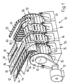
- the plug-in device 10 shown schematically in FIG. 1 is largely of a known type and is described in detail in CH-PS 575 303 and 584 153 and the corresponding US Pat. Nos. 4,058 202 and 3 951 399. For this reason, the explanations relating to the known structure and the known mode of operation are limited to the essentials below.
- the most important component of the plug-in device 10 is a horizontal-axis, elongated cell wheel 12, which is divided into several sections 14, 16, 18, 20, which are arranged next to one another in the direction of the axis 22 of the cell wheel 12 and are connected to one another in a rotationally fixed manner.
- An input section 14 is followed by two feed sections 16 and 18 and a removal section 20.
- Each section 14-20 has radial pockets 24 which are open to the outside and are separated from one another by pocket walls 26.
- the cellular wheel 12 is supported on rollers 28 which are freely rotatably mounted in a base frame 30. As shown schematically in Fig. 1, the cellular wheel 12 is driven by a drive 32 in the direction of arrow A about its axis 22.
- a feeder designated 34, 36 or 38 leads to the input section 14 and each feed section 16 or 18 and runs above the assigned section 14, 16 or 18. Every carrier 34 - 38 is in with Intervals arranged but not shown clamps equipped. Each feed dog is guided around a deflection roller 40.
- the conveyor 34 is used to feed two superimposed printing products 42 and 44 to the input section 14 in a shingled formation.
- the printed products 42 and 44 are parts of newspapers, magazines or the like which are folded at least once, single- or multi-leaf parts.
- the clamp pliers not shown, grip the printed products 42, 44 at their rear edge as seen in the conveying direction, ie in the fold removed Field of flower.
- the printed products 42, 44 After rotating around the deflection roller 40 and the deflection plate 46, the printed products 42, 44 reach a hanging position in which they protrude into the pockets 24 of the input section 14.
- the printed products 42, 44 are released by opening the clamping pliers, with the result that the printed products 42, 44 fall onto the bottom of the assigned pocket 24.
- preliminary products 48 and 50 (inserts) are fed to the feed section 16 and 18 by the transporter 36 and 38, respectively.
- the removal section 20 is also assigned an overshot conveyor 52 which also has clamping tongs 54 arranged at mutual intervals and is guided around a deflection roller 56.
- the clamping pliers 54 capture in a manner known per se (compare CH-PS 649 267 or US Pat. No. 4,416,448) the two end products 58 and 60 lying one on top of the other in a pocket 24 of the removal section 20 and lift these end products 58, 60 out of the pocket 24 out.
- the end products 58 transported in a hanging position, as shown in FIG. 1, 60 can now be processed.
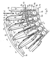
- the printed products 42, 44 introduced into the pockets 24 of the input section 14 in the manner described above come to rest on a pocket wall 26 during the rotation of the cellular wheel 12, as can be seen from FIG. 2.
- the printed product 44 is then displaced in the conveying direction B with respect to the printed product 42, as will be explained in more detail below.
- a wedge-shaped contact element 62 fastened to this pocket wall 26 through which the printed products 42, 44 lying on them move somewhat from the partition wall 26 in their leading region be lifted off.
- the opening of the printed product 44 at its leading edge 64 is carried out in a known manner, as described, for example, in CH-PSs 644 814 and 644 815, respectively.
- the corresponding U.S. Patents 4,398,710 and 4,420,146; the opening thereby formed in the printed product 44 is denoted by 66.
- the printed products 42 and 44 pass into the adjacent pocket 24 of the feed section 16 during their common advancement in the conveying direction B.
- each pocket 24 of this feed section 16 there is a stationary separating wedge 68 to which the printed product 44 runs.
- the separating wedge 68 engages in the opening 66 of the printed product 44 and, when the printed products 42, 44 move further, causes the two halves of the printed product 44 to open completely.
- the guide plates 70, 72 adjoining the separating wedge 68 keep the printed product 44 open.
- a preliminary product 48 (insert) is now introduced into the open printed product 44 through an insertion opening 74 opening into the space formed between the guide plates 70, 72.
- the other printed product 42 is also transported without being subjected to processing. Before the two printed products 42 and 44 are conveyed to the next feed section 18, they are, as described, for example, in the already mentioned CH-PS 575 303, respectively. US Pat. No. 4,058,202 is so oriented that the leading edges 64 of both printed products 42, 44 are arranged at the same height as seen in the conveying direction B. After the preliminary product 48 has been inserted into the printed product 44 and the two printed products 42 and 44 have been aligned, the second printed product 42 is opened in an analogous manner, as described above in connection with the opening of the printed product 44.
- the printed product 42 runs onto a separating wedge 76 which is arranged in the adjacent pocket 24 of the second feed section 18.
- This separating wedge 76 brings about a complete opening of this printed product 42 by moving into an opening 66 formed in the printed product 42, which is kept open by baffles 78, 80 adjoining the separating wedge 76.
- a preliminary product 50 is inserted into the open printed product 42 through an insertion opening 82, which communicates with the space formed between the guide plates 78, 80.
- the printed product 44 leaves the guide plates 70, 72 and is closed.
- the two printed products 42, 44, each provided with a preliminary product 48 or 50, are now transported from the feed section 18 into the removal section 20, the printed product 42 running off and closing from the guide plates 78, 80 during this displacement.
- the end products 58, 60 lying one on top of the other are pulled out of the pockets 24 of the removal section 20 by means of the conveyor 52 and transported away.
- a displacement device 84 with which the two printed products 42, 44 are displaced relative to one another in the input section 14, will now be explained in more detail with reference to FIGS.
- Fig. 3 shows a side view in the direction of the axis 22 (see Fig. 1) that part of the input section 14 of the cellular wheel 12, in which the printed products 42, 44 are inserted into the pockets 24 and shifted against each other, a cover 86, cf. also Fig. 4, is not shown. As in FIG. 4, only those parts are shown in FIG. 3 that are necessary for understanding the displacement device 84. In this context, again on the already mentioned CH-PS 575 303 resp. Reference is made to US Pat. No. 4,095,820 in which a conveying device 88 for transporting the printed products 42, 44 along the processing path is described in more detail.
- Fig. 3 pockets 24 '- 24'''' of the input section 14 are shown, the pockets 24 by front and rear pocket plates 90 and. 92 and the conveyor 88 are formed.
- Support ring 94 are arranged radially outwardly projecting and extending in the longitudinal direction of the cellular wheel 12 rails 96.
- the profile rails 96 have a substantially C-shaped profile, extend practically over the entire length of the cellular wheel 12 and are fastened, for example, to the support ring 94 by means of screw bolts.
- a carriage 98 is slidably mounted in each profile rail 96 by means of rollers 100.
- a v-shaped baffle 102 is arranged on the carriage 98, which forms the bottom of the pocket 24 and on which a stop 104 is arranged on the leg projecting from the carriage 98.
- a pivot shaft 106 is likewise pivotably mounted on the carriage 98, on which gripping fingers 108 are arranged in a rotationally fixed manner. The ends of the gripping fingers 108 protruding from the pivot shaft 106 are positioned in an open position outside of a space formed by the V-shaped legs of the guide plate 102, while they penetrate and open openings in the guide plate 102 which are not visible in the clamping position in this FIG the print products 42, 44 come to rest.
- the profile rails 96 are connected to one another at their ends remote from the support ring 94 with cover plates 110.
- the cover plates 110 are shown broken off at the pocket 24 '' 'and not shown at the pockets 24' '' 'and 24' '' ''. Seen in the axial direction, the cover plates 110 only expand over a first short part of the profile rails 96 (cf. FIG. 4).
- a partition profile 112 is fastened to each profile rail 96 in a manner not shown.
- the free end of the Partition profile 112 is bent forward in the direction of rotation A of the cellular wheel 12.
- Two torsion bars 114 are attached at one end to the offset of the partition profile 112 and at the other end to a connecting profile 126.
- an actuating lever 116 is arranged on the free end of which a follower 118, here two rollers, is rotatably mounted on a stub shaft 120, which are supported against the force of the torsion bars 114 on a stationary link 122.
- the link 122 coaxially encompasses the cellular wheel 12 in the region of the input section 14.
- a follower surface 124 of the link 122 on which the follower 118 slides is spaced further apart from the axis 22 in a clamping region C than over its remaining length. This allows a temporary deflection of the actuating lever 116 in the clockwise direction in the clamping area C.
- the rear pocket plate 92 is fastened in a rotationally fixed manner to the connecting profile 126.
- a rear insert plate 130 is connected by means of screw bolts 128.
- the rear insert plate 130 is provided with a clamping pad 132. The function of the clamping member 92, 114-132 is described in more detail below.
- the front pocket plate 90 is also fastened to the partition profile 112 by means of schematically illustrated connecting parts 134. In the upper area it is bent and covers the bent end of the partition profile 112. At the radially inward end, a front insert plate 138 is fastened to the front pocket plate 90 by means of screw bolts 136. On this front insert plate 138 there is a slide 142 provided with a sliding support 140, which will be described later. slidably mounted. A support profile 144 is arranged between the front insert plate 138 and the partition wall profile 112. A tension profile 146 is attached to the partition profile 112 opposite the support profile 144. The task and effect of this train profile 146 need not be discussed further in this context. Stop elements 148 are fastened to the tension profile 146, on which the screw bolts 128 come to rest when the rear pocket plate 92 is pivoted back.
- a guide body 150 is fastened to each cover plate 110 by means of screw bolts 152.
- a support body 154 is also fastened to the cover 86, not shown in this figure, by means of screw bolts 156, see FIG. 4.
- a driver lever 158 which interacts with the stop 104, the guide body 150 and the support body 154 are parts of the displacement device 84 and are associated with 4 and 5 described in more detail.
- Fig. 4 is a partially sectioned and broken side view in the direction of arrow IV of Fig. 3.
- the cover plate 110 connects the profile rail 96 to one of the neighboring ones and the guide body 150 is fastened to it with the screw bolts 152.
- a displacement rod 160 is slidably guided in the guide body 150.
- the driving lever 158 is arranged on the displacement rod 160 in a rotationally fixed manner by means of a screw 162, while on the other hand it is arranged on the displacement rod 160 by means of an adjusting nut 164 and an adjusting screw 166 with a pivot joint 168 is connected.
- the swivel joint 168 is connected to the displacement rod 160 in a rotatable manner but not displaceably in the axial direction.
- a ball 172 which slides in a guide groove 174 in the displacement rod 160, is arranged in a bore 170 in the guide body 150 in a spring-loaded manner. This prevents the displacement bar 160 from rotating about its longitudinal axis.
- a guide depression not visible in this figure, is arranged in the displacement rod 160 by approximately 120 ° to the guide groove 174. More about this in connection with FIG. 5.
- the partition profile 112 is arranged on the profile rail 96 and is connected to the adjacent partition profiles 112 by means of the cover 86.
- the support body 154 is fastened to the cover 86 by means of the screw bolt 156.
- the guide body 150 and the support body 154 are shown in section.
- a pinion 176 is rotatably mounted on a bearing shaft 174.
- the toothed pinion is in engagement with a toothed rack 178 and a toothing 182 arranged on a tappet 180.
- the toothed rack 178 can be rotated with the swivel joint 168 in the same way as the displacement rod 160, but is not displaceably connected in the axial direction.
- a tension spring 186 is fastened to a cantilever 184 of the rack 178, the other end of which is operatively connected to the supporting body 154 by means of a pin 190.
- the partition profile 112 is covered by the front pocket plate 90 in the area in which the printed products 42, 44 are introduced into the cellular wheel 12.
- the torsion bars 114 are also covered.
- the link 122 is supported by a bracket 192 which is attached to one only indicated frame 194 is attached.
- the front insert plate 138 is fastened to the broken front pocket plate 90 by means of screws or rivets 196.
- a return spring 202 is connected at one end to a holding member 204 which is also arranged on the front insert plate 138 and at the other end to a block 206 which is operatively connected to the slide 142.
- the sliding support 140 which is only partially indicated with oblique hatching, is arranged on the slide 142.
- the plunger 180 comes with its end remote from the support body 154 to a stop member 208 of the slide 142 to the plant.
- the two superimposed printed products 42, 44 are indicated by dash-dotted lines.
- the shifting device 84 transferred in the actuation position is also indicated by dash-dotted lines.
- FIG. 5 shows, in an enlarged representation compared to FIG. 3, the displacement device 84 with the adjacent parts which are only partially shown.
- the reference numbers in this figure correspond to the reference numbers already mentioned in the other figures. The parts marked with these are no longer specifically dealt with.
- the driver lever 158 is pivoted here from the position shown in FIGS. 3 and 4 with solid lines and in this FIG. 5 with dash-dotted lines by approximately 120 ° clockwise.
- the driver lever 158 is pivoted and fixed out of the area of the stop 104 and can no longer be actuated by the latter.
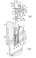
- FIG. 6 shows a perspective view of a section along the section line VI-VI in FIG. 4, the conveying device 88 not being shown.
- the clamping position shown with solid lines corresponds to the position of the clamping member, as shown in Fig. 3, pocket 24 '''', while the position shown in broken lines corresponds to the position of the clamping member in the other pockets 24 of Fig. 3.
- Sliding pad 132, 140 are made of a rubber or rubber-like material, which has a high coefficient of friction compared to paper.
- This high coefficient of friction and the surface structure of the clamping and sliding pad 132, 140 leads to good power transmission between the clamping or the sliding element onto the printed products 42, 44 clamped in between.
- the opposing surfaces of the front insert plate 138 and the slide 142 are provided with a surface coating with good sliding properties.
- the two main printing products 42, 44 in the input section 14 are shifted in their relative position to one another by means of the shifting device 84, before they are transported to the subsequent feed section 16.
- the carriage 98 with the parts arranged on it moves back and forth parallel to the axis 22 along a processing path, with the printed products 42, 44 from the input section 14 to the feed sections 16 and 18 and from there together with the inserted preliminary products 48, 50 to the removal section 20.
- the description of the actuation process of the pivot shaft 106 with the gripping fingers 108 can also be found in these mentioned patents.
- the cellular wheel 12 rotates in the direction of arrow A and the carriage 98 moves during the return movement against the direction of conveyance B.
- the main products 42, 44 released by the transporter 34 fall into the pocket denoted by 24 '. Since the rear pocket plate 92 is pressed against the stop piece 145 by means of the lever link arrangement 116, 122, the way is clear for the printed products 42, 44 to rest on the guide plate 102. So that they do not move against the conveying direction B with the carriage 98, they are held in their axial position by guides, not shown. Shortly before the carriage 98 reaches the position shown in Fig.
- the pocket 24 'in the direction of arrow A to the pocket 24''' further moves and the follower 118 reaches the clamping area C, which has a pivoting of the operating lever 116 and the rear pocket plate 92 in a counterclockwise direction.
- the printed products 42, 44 are clamped between the sliding pad 140 and the clamping pad 132.
- the stop 104 comes to rest on the driver lever 158 and shifts it into the position shown in broken lines in FIG. 4. This movement is transmitted to the rack 178 by the displacement rod 160 and the swivel joint 168, the tension spring 186 being tensioned.
- the movement of the rack 178 leads to a clockwise rotation of the pinion 176, which in turn leads to a displacement of the plunger 180 in the conveying direction B.
- the plunger 180 acts on the stop element 208 of the slide 142 and moves it against the force of the return spring 202 also in the conveying direction B, which in turn has the consequence that the printed product 44 resting on the sliding support 140 compared to the printed product 42 resting on the clamping support 132 is moved in the direction of conveyance B.
- the radius of the link 122 decreases again, which has the consequence that the rear pocket plate 92 is pivoted counterclockwise and the clamping pad 132 is lifted off the printed product 42.
- the direction of movement of the carriage 98 is reversed, the gripping fingers 108 are pivoted, so that the printed products 42, 44 which are displaced relative to one another are moved along with the carriage 98 in the conveying direction B.
- the displacement rod 160 and the plunger 180 are moved back into their original rest position by the force of the tension spring 186.
- the tensioned return spring 202 ensures that the slide 142 also returns to its rest position.
- the conveyor 88 transports the printed products 42, 44 to the feed section 16 and then runs back to the position shown in FIG. 4, the next pair of printed products 42, 44 being placed in the same pocket 24 again.
- the displacement device 84 must be able to be blocked.
- the driver lever 158 must be pivoted out of the area of the stop 104, as is shown in FIG. 5. In this position, the ball 172 is immersed in the bore 170 in the guide recess on the displacement rod 160, so that the displacement rod 160 is secured against rotation and pivoting about its longitudinal axis. In order to reactivate the displacement device, only the driver lever 158 therefore has to be pivoted back into the position shown in broken lines in FIG. 5.
Abstract
Description
Die vorliegende Erfindung betrifft eine Vorrichtung zum Einbringen wenigstens einer Einlage in Druckprodukte, insbesondere zum Einstecken mindestens einer Beilage in gefaltete Druckerei-Hauptprodukte gemäss dem Oberbegriff des Anspruches 1.The present invention relates to a device for inserting at least one insert into printed products, in particular for inserting at least one insert into folded main printing products according to the preamble of claim 1.
Eine solche Vorrichtung ist aus der CH-PS 649 267 und der entsprechenden US-PS 44 16 448 bekannt. Bei dieser Vorrichtung werden jeweils zwei übereinander liegende Druckprodukte gemeinsam entlang eines Verarbeitungsweges transportiert, nacheinander geöffnet und in die jeweils gebildete Qeffnung eine Einlage eingeführt. Um die aufeinanderliegenden Druckprodukte öffnen zu können, wird die vorlaufende Kante eines Druckproduktes freigelegt. Dies geschieht dadurch, dass die Fördereinrichtung beim Zurücklaufen ein Druckprodukt um eine gewisse Strecke mitnimmt, während das andere Druckprodukt durch einen Anschlag an einer Mitnahme in Richtung der zurücklaufenden Fördereinrichtung gehindert wird. Es ist einzusehen, dass bei dieser bekannten Vorrichtung das Verschieben zweier aufeinanderliegender dünner Druckprodukte zu Schwierigkeiten führen kann. Der durch das mitgenommene Produkut zu überfahrende Anschlag darf in einem solchen Fall nur sehr wenig vorstehen, um das zweite Druckprodukt nicht zu verletzen und er muss doch soweit vorstehen, dass das erste Druckprodukt sicher zurückgehalten wird. Es ist in einem solchen Fall notwendig, für die Verarbeitung von dickeren Druckprodukten den Anschlag anzupassen und zu verstellen. Dasselbe gilt analog für die Umstellung von dicken Druckprodukten auf dünnere. Dies führt zu Einstellarbeiten bevor die Vorrichtung in Betrieb genommen werden kann.Such a device is known from CH-PS 649 267 and the corresponding US-
Aufgabe der vorliegenden Erfindung ist es, eine Vorrichtung der eingangs genannten Art zu schaffen, die es erlaubt, Druckprodukte verschiedenster Dicke ohne vorgängige Einstellarbeiten sicher und schonend gegeneinander zu verschieben.The object of the present invention is to provide a device of the type mentioned at the outset which allows printed products of various thicknesses to be shifted safely and gently against one another without prior adjustment work.
Diese Aufgabe wird durch die Merkmale des kennzeichnenden Teiles des Anspruches 1 gelöst.This object is achieved by the features of the characterizing part of claim 1.
Die aufeinanderliegenden Druckprodukte werden vom Klemmorgan und Schiebeorgan gehalten und gegeneinander verschoben. Dadurch dass die beiden Organe auf den Aussenflächen der Druckprodukte angreifen, kann die Angriffsfläche gross ausgebildet werden, was zu geringen Beanspruchungen in den Druckprodukten führt und insbesondere eine Schonung der Kanten der Druckprodukte zur Folge hat. Die Dicke der Druckprodukte hat auf die Grösse der Angriffsflächen keinen Einfluss.The superimposed printed products are held by the clamping element and sliding element and shifted against each other. Due to the fact that the two organs act on the outer surfaces of the printed products, the contact surface can be made large, which leads to low stresses in the printed products and, in particular, results in the edges of the printed products being protected. The thickness of the printed products has no influence on the size of the attack surfaces.
Das Klemmorgan ist vorzugsweise um eine Achse parallel zum Verarbeitungsweg schwenkbar und gegen die Klemmstellung vorgespannt gelagert und mittels einer Kulissensteuerung in die Oeffungsstellung bringbar. Dies führt zu einer sicheren und von der Dicke der Druckprodukte unabhängigen Halterung derselben.The clamping member can preferably be pivoted about an axis parallel to the processing path and is preloaded against the clamping position and can be brought into the open position by means of a link control. This leads to a secure mounting of the printed products, regardless of the thickness of the printed products.
Vorzugsweise weist das Schiebeorgan einen parallel zum Verarbeitungsweg schiebbar gelagerten Schieber und ein auf den Schieber einwirkende, mittels der zurücklaufenden Wagenanordnung betätigbare Antriebsanordnung auf. Die Rückwärtsbewegung der Fördereinrichtung wird dabei ausgenützt, um die Druckprodukte gegeneinander zu verschieben.The sliding member preferably has a slide which is mounted parallel to the processing path and a drive arrangement which acts on the slide and can be actuated by means of the returning carriage arrangement. The backward movement of the conveyor is used to move the printed products against each other.
In einer bevorzugten Ausführungsform sind das Klemmorgan sowie das Schiebeorgan mit einer Auflage, welche einen grossen Reibungskoeffizienten aufweist vorzugsweise aus Gummi oder einem Kunststoff, überzogen. Dadurch wird das sichere Verschieben resp. Zurückhalten der Druckprodukte garantiert. Die Oberflächen der Auflagen sind vorteilhafterweise sägezahnartig ausgebildet, was die Reibungsmitnahme noch verstärkt.In a preferred embodiment, the clamping member and the sliding member are coated with a support which has a large coefficient of friction, preferably made of rubber or a plastic. This will safely move or Retention of the printed products guaranteed. The surfaces of the supports are advantageously sawtooth-like, which further increases the frictional drag.
In einer weiteren bevorzugten Ausführungsform ist ein Mitnehmerhebel des Antriebsorganes aus dem Bereich der Wagenanordnung schwenkbar. Damit kann auf sehr einfache Art und Weise die Verschiebeeinrichtung ausgeschaltet werden.In a further preferred embodiment, a driver lever of the drive element can be pivoted out of the area of the carriage arrangement. The displacement device can thus be switched off in a very simple manner.
Die Verschiebeeinrichtung ist bevorzugterweise in einem Eingabeabschnitt eines umlaufend angetriebenen Zellenrades angeordnet, das radial verlaufende Taschen zur Aufnahme der Druckprodukte und in axialer Richtung dem Eingabeabschnitt aufeinanderfolgend wenigstens zwei Zuführabschnitte für die Einlagen sowie einen Entnahmeabschnitt aufweist. Dies ermöglicht eine platzsparende Anordnung der Verschiebeeinrichtung und deren Einbau in bestehende Zellenräder.The displacement device is preferably arranged in an input section of a rotatingly driven cellular wheel, which has radially extending pockets for receiving the printed products and in the axial direction the input section successively has at least two feed sections for the inserts and a removal section. This enables a space-saving arrangement of the displacement device and its installation in existing cellular wheels.
In einer weiteren bevorzugten Ausführungsform ist das Klemmorgan an einer Taschenrückwand und das Schiebeorgan an einer Taschenvorderwand angeordnet. Die beiden Organe können dabei die Funktion der Begrenzung der Taschenwände übernehmen, was die Vorrichtung sehr vereinfacht.In a further preferred embodiment, the clamping element is arranged on a pocket rear wall and the sliding element on a pocket front wall. The two organs can take over the function of limiting the pocket walls, which simplifies the device very much.
Weitere bevorzugte Ausbildungen der Vorrichtung sind in der weiteren abhängigen Ansprüchen angegeben.Further preferred configurations of the device are specified in the further dependent claims.
Ein Ausführungsbeispiel des Erfindungsgegenstandes wird nun anhand der Figuren näher beschrieben. Es zeigen rein schematisch:
- Fig. 1 eine vereinfachte perspektivische Darstellung einer Vorrichtung zum Einstecken von Beilagen in Druckerei-Hauptprodukte,
- Fig. 2 in Draufsicht ein Teil des Zellenrades der Einrichtung gemäss der Fig. 1, wobei der Ablauf des Einsteckvorganges zeitlich gerafft dargestellt ist,
- Fig. 3 eine teilweise vereinfachte Seitenansicht eines Teils des Zellenrades gemäss der Fig. 1,
- Fig. 4 eine Ansicht des Zellenrades gemäss Fig. 3 in Pfeilrichtung IV,
- Fig. 5 eine vergrösserte Darstellung eines Teiles der Fig. 3 und
- Fig. 6 einen Schnitt entlang der Linie VI-VI in perspektivischer Darstellung des Zellenrades gemäss Fig. 4.
- 1 is a simplified perspective view of a device for inserting inserts into printing main products,
- FIG. 2 shows a top view of part of the cellular wheel of the device according to FIG. 1, the sequence of the insertion process being shown in time,
- 3 is a partially simplified side view of part of the cellular wheel according to FIG. 1,
- 4 shows a view of the cellular wheel according to FIG. 3 in the direction of arrow IV,
- Fig. 5 is an enlarged view of a part of FIGS. 3 and
- 6 shows a section along the line VI-VI in a perspective view of the cellular wheel according to FIG. 4.
Die in der Fig. 1 schematisch dargestellte Einsteckeinrichtung 10 ist weitgehend bekannter Bauart und in den CH-PS'en 575 303 und 584 153 bzw. den entsprechenden US-PS'en 4 058 202 und 3 951 399 ausführlich beschrieben. Aus diesem Grund beschränken sich im folgenden die den bekannten Aufbau und die bekannte Wirkungsweise betreffenden Ausführungen auf das Wesentliche.The plug-in
Der wichtigste Bestandteil der Einsteckeinrichtung 10 ist ein horizontalachsiges, langgestrecktes Zellenrad 12, das in mehrere Abschnitte 14, 16, 18, 20 unterteilt ist, die in Richtung der Achse 22 des Zellenrades 12 nebeneinander angeordnet und drehfest miteinander verbunden sind. An einen Eingabeabschnitt 14 schliessen zwei Zuführabschnitte 16 und 18 und ein Entnahmeabschnitt 20 an. Jeder Abschnitt 14 - 20 weist radiale nach aussen offene Taschen 24 auf, die durch Taschenwände 26 voneinander getrennt sind. Das Zellenrad 12 ist auf Rollen 28 abgestützt, die frei drehbar in einem Untergestell 30 gelagert sind. Wie in Fig. 1 schematisch dargestellt, ist das Zellenrad 12 durch einen Antrieb 32 in Richtung des Pfeiles A um seine Achse 22 angetrieben.The most important component of the plug-in
Zum Eingabeabschnitt 14 und jedem Zuführabschnitt 16 bzw. 18 führt ein mit 34, 36 bzw. 38 bezeichneter Transporteur, der oberhalb des zugeordneten Abschnittes 14, 16 bzw. 18 verläuft. Jeder Transporteur 34 - 38 ist mit in Abständen angeordneten aber nicht dargestellten Klemmzangen ausgerüstet. Jeder Transporteur wird um eine Umlenkrolle 40 herumgeführt. Der Transporteur 34 dient dazu, jeweils zwei aufeinanderliegende Druckerei-Hauptprodukte 42 und 44 in Schuppenformation dem Eingabeabschnitt 14 zuzuführen. Bei den Druckprodukten 42 und 44 handelt es sich um wenigstens einmal gefaltete, ein- oder mehrblättrige Teile von Zeitungen, Zeitschriften oder dgl. Die nicht dargestellten Klemmzangen ergreifen dabei die Druckprodukte 42, 44 an ihrem in Förderrichtung gesehen hinteren Rand, d.h. im dem Falz entfernten Bereich der Blume. Die Druckprodukte 42, 44 gelangen nach dem Umlaufen um die Umlenkrolle 40 und das Umlenkblech 46 in eine hängende Lage, in der sie in die Taschen 24 des Eingabe- abschnittes 14 hineinragen. Durch Oeffnen der Klemmzangen werden die Druckprodukte 42, 44 freigegeben, was zur Folge hat, dass die Druckprodukte 42, 44 auf den Grund der zugeordneten Tasche 24 fallen. Auf entsprechende Weise werden dem Zuführabschnitt 16 bzw. 18 durch den Transporteur 36 bzw. 38 Vorprodukte 48 bzw. 50 (Beilagen) zugeführt.A feeder designated 34, 36 or 38 leads to the
Dem Entnahmeabschnitt 20 ist ebenfalls ein oberschlächtiger Transporteur 52 zugeordnet, der auch in gegenseitigen Abständen angeordnete Klemmzangen 54 aufweist und um eine Umlenkrolle 56 herumgeführt wird. Die Klemmzangen 54 erfassen auf an sich bekannte Weise (vergleiche CH-PS 649 267 bzw. US-PS 4 416 448) jeweils die beiden in einer Tasche 24 des Entnahmeabschnittes 20 aufeinanderliegenden Endprodukte 58 und 60 und heben diese Endprodukte 58, 60 aus der Tasche 24 heraus. Die wie in Fig. 1 dargestellt in hängender Lage weitertransportierten Endprodukte 58, 60 können nun weiterverarbeitet werden.The
In jede Tasche 24 des Eingabeabschnittes 14 werden somit zwei Hauptprodukte 42 und 44 eingelegt. Wie das noch näher zu erläutern sein wird, werden nun diese Hauptprodukte 42 und 44 übereinanderliegend gemeinsam in Achsrichtung des Zellenrades 12 zum Entnahmeabschnitt 20 verschoben. Im Zuge dieser Bewegung wird in jedes der Druckprodukte 42, 44 ein Vorprodukt 48 bzw. 50 eingelegt. Die mit diesen Vorprodukten 48, 50 versehenen Endprodukte 58 und 60 werden wieder gemeinsam dem Entnahmeabschnitt 20 entnommen.Two
Anhand der Fig. 2 wird nun der Oeffnungs- und Einsteckvorgang näher erläutert. Bei der in dieser Fig. 2 gezeigten Darstellung ist die Drehung des Zellenrades 12 nicht berücksichtigt. In Wirklichkeit bewegen sich die Druckprodukte 42, 44 nicht wie gezeigt entlang einer geradlinigen Bewegungsbahn, sondern entlang einer wendel- oder schraubenlinienförmigen Bahn. Das gemeinsame Vorschieben der Druckprodukte 42, 44 vom Eingabeabschnitt 14 zum Entnahmeabschnitt 20 erfolgt auf die, in der bereits früher erwähnten CH-PS 575 303 (und der entsprechenden US-PS 4 058 202) bzw.in der CH-PS 584 153 (und der entsprechenden US-PS 3 951 399) beschriebene Weise. Betreffend Aufbau und Wirkungsweise der Fördereinrichtung zum Vorschieben der Druckprodukte 42, 44, die in den Figuren nicht oder nur teilweise dargestellt ist, wird daher auf diese vorstehend erwähnten Druckschriften verwiesen.The opening and insertion process will now be explained in more detail with reference to FIG. 2. In the illustration shown in FIG. 2, the rotation of the
Die auf die oben beschriebene Weise in die Taschen 24 des Eingabeabschnittes 14 eingeführten Druckprodukte 42, 44 kommen während der Drehung des Zellenrades 12 auf einer Taschenwand 26 zur Auflage, wie das aus der Fig. 2 hervorgeht. Anschliessend wird das Druckprodukt 44 gegenüber dem Druckprodukt 42 in Förderrichtung B verschoben, wie dies weiter unten im Detail noch zu erläutern sein wird. Beim anschliessenden gemeinsamen Transport der beiden Druckprodukte 42, 44 in Förderrichtung B entlang einem Verarbeitungsweg kommen diese auf ein keilförmig ausgebildetes, an dieser Taschenwand 26 befestigtes Anlageelement 62 zur Auflage, durch welches die aufliegenden Druckprodukte 42, 44 in ihrem vorlaufenden Bereich etwas von der Trennwand 26 abgehoben werden. Das Oeffnen des Druckproduktes 44 an seiner vorlaufenden Kante 64 erfolgt in bekannter Art und Weise wie dies z.B.in den CH-PS'en 644 814 und 644 815 resp. den entsprechenden US-PS'en 4 398 710 und 4 420 146 beschrieben ist; die dadurch im Druckprodukt 44 gebildete Oeffnung ist mit 66 bezeichnet.The printed
Die Druckprodukte 42 und 44 gelangen während ihres gemeinsamen Vorschiebens in Förderrichtung B in die benachbarte Tasche 24 des Zuführabschnittes 16. In jeder Tasche 24 dieses Zuführabschnittes 16 befindet sich ein ortsfester Trennkeil 68, auf den das Druckprodukt 44 zuläuft. Der Trennkeil 68 greift in die Oeffnung 66 des Druckproduktes 44 ein und bewirkt bei der Weiterbewegung der Druckprodukte 42, 44 ein vollständiges Oeffnen der beiden Hälften des Druckproduktes 44. Durch die an den Trennkeil 68 anschliessenden Leitbleche 70, 72 wird das Druckprodukt 44 offengehalten. Durch eine in den zwischen den Leitblechen 70, 72 gebildeten Raum einmündende Einführöffnung 74 wird nun ein Vorprodukt 48 (Beilage) in das offene Druckprodukt 44 eingeführt.The printed
Während dem Oeffnen des Druckproduktes 44 und dem Einführen des Vorproduktes 48 wird das andere Druckprodukt 42 mittransportiert, ohne dass es einer Verarbeitung unterworfen wird. Bevor die beiden Druckprodukte 42 und 44 zum nächsten Zuführabschnitt 18 gefördert werden, werden sie, wie dies beispielsweise in der schon mehrmals erwähnten CH-PS 575 303 resp. US-PS 4 058 202 beschrieben ist, so ausgerichtet, dass die vorlaufenden Kanten 64 beider Druckprodukte 42, 44 in Förderrichtung B gesehen auf gleicher Höhe angeordnet sind. Nach dem Einlegen des Vorproduktes 48 in das Druckprodukt 44 und das Ausrichten der beiden Druckprodukte 42 und 44 erfolgt eine Voröffnung des zweiten Druckproduktes 42 auf analoge Weise, wie dies weiter oben im Zusammenhang mit der Oeffnung des Druckproduktes 44 beschrieben ist. Während der gemeinsamen Weiterbewegung der beiden Druckprodukte 42, 44 läuft das Druckprodukt 42 auf einen Trennkeil 76 auf, der in der benachbarten Tasche 24 des zweiten Zuführabschnittes 18 angeordnet ist. Dieser Trennkeil 76 bewirkt gleich wie der Trennkeil 68 durch Einfahren in eine im Druckprodukt 42 gebildete Oeffnung 66 ein vollständiges Oeffnen dieses Druckproduktes 42, das durch, an den Trennkeil 76 anschliessende Leitbleche 78, 80 offengehalten wird. Durch eine Einführöffnung 82, die mit dem zwischen den Leitblechen 78, 80 gebildeten Raum in Verbindung steht, wird in das offene Druckprodukt 42 ein Vorprodukt 50 eingelegt. Während des Vorschiebens der Druckprodukte 42, 44 vom Zuführabschnitt 16 in den Zuführabschnitt 18 verlässt das Druckprodukt 44 die Leitbleche 70, 72 und wird geschlossen.During the opening of the printed
Vom Zuführabschnitt 18 werden nun die beiden je mit einem Vorprodukt 48 bzw. 50 versehenen Druckprodukte 42, 44 in den Entnahmeabschnitt 20 transportiert, wobei während dieser Verschiebung das Druckprodukt 42 von den Leitblechen 78, 80 abläuft und sich schliesst. Die aufeinanderliegenden Endprodukte 58, 60 werden wie bereits erwähnt mittels des Transporteurs 52 aus den Taschen 24 des Entnahmeabschnittes 20 herausgezogen und wegtransportiert.The two printed
Nun wird anhand der Figuren 3 - 6 eine Verschiebeeinrichtung 84 näher erläutert, mit welcher die beiden Druckprodukte 42, 44 im Eingabeabschnitt 14 relativ zueinander verschoben werden.A
Fig. 3 zeigt in Seitenansicht in Richtung der Achse 22 (siehe Fig. 1) jenen Teil des Eingabeabschnittes 14 des Zellenrades 12, in dem die Druckprodukte 42, 44 in die Taschen 24 eingeführt und gegeneinander verschoben werden, wobei eine Abdeckung 86, vergl. dazu auch Fig. 4, nicht gezeigt ist. Es sind in der Fig. 3 wie auch in der Fig. 4 nur jene Teile dargestellt, die für das Verständnis der Verschiebeeinrichtung 84 notwendig sind. In diesem Zusammenhang wird nochmals auf die schon mehrmals erwähnte CH-PS 575 303 resp. US-PS 4 0958 202 verwiesen, in welcher eine Fördereinrichtung 88 zum Transportieren der Druckprodukte 42, 44 entlang des Verarbeitungsweges näher beschrieben ist.Fig. 3 shows a side view in the direction of the axis 22 (see Fig. 1) that part of the
In der Fig. 3 sind 5 Taschen 24′ - 24′′′′′ des Eingabeabschnittes 14 dargestellt, wobei die Taschen 24 durch vordere und hintere Taschenbleche 90 resp. 92 und die Fördereinrichtung 88 gebildet sind. An einem nur teilweise dargestellten, um die Achse 22 drehbar gelagerten Stützring 94, sind radial nach aussen abstehende und in Längsrichtung des Zellenrades 12 verlaufende Profilschienen 96 angeordnet. Die Profilschienen 96 haben im wesentlichen ein C-förmiges Profil, verlaufen praktisch über die ganze Länge des Zellenrades 12 und sind beispielsweise mittels Schraubenbolzen am stützring 94 befestigt. In jeder Profilschiene 96 ist ein Wagen 98 mittels Rollen 100 verschiebbar gelagert. Am Wagen 98 ist ein v-förmiges Leitblech 102 angeordnet, welches den Boden der Tasche 24 bildet und an welchem am vom Wagen 98 abstehenden Schenkel eine Anschlag 104 angeordnet ist. Am Wagen 98 ist ebenfalls eine Schwenkwelle 106 schwenkbar gelagert, an welcher Greiffinger 108 drehfest angeordnet sind. Die von der Schwenkwelle 106 abstehenden Enden der Greiffinger 108 sind in einer Oeffnungsstellung ausserhalb eines durch die V-förmigen Schenkel des Leitbleches 102 gebildeten Raumes positioniert, während sie bei der Ueberführung in eine Klemmstellung in dieser Fig. nicht sichtbare Oeffnungen im Leitblech 102 durchdringen und auf die Druckprodukte 42, 44 zur Anlage kommen.In Fig. 3 5 pockets 24 '- 24''''' of the
Die Profilschienen 96 sind an ihren vom Stützring 94 entfernten Enden mit Abdeckblechen 110 miteinander verbunden. Um eine bessere Uebersicht zur gewährleisten, sind die Abdeckbleche 110 bei der Tasche 24′′′ abgebrochen gezeichnet und bei der Taschen 24′′′′ und 24′′′′′ nicht dargestellt. In Axialrichtung gesehen dehnen sich die Abdeckbleche 110 nur über einen ersten kurzen Teil der Profilschienen 96 aus (vergl. Fig. 4).The profile rails 96 are connected to one another at their ends remote from the
An jeder Profilschiene 96 ist auf nicht dargestellte Weise ein Trennwandprofil 112 befestigt. Das freie Ende des Trennwandprofils 112 ist in Drehrichtung A des Zellenrades 12 nach vorn abgekröpft. Zwei Torsionsstäbe 114 sind einerends an der Abkröpfung des Trennwandprofils 112 und andernends an einem Verbindungsprofil 126 befestigt. Am Verbindungsprofil 126 ist ein Betätigungshebel 116 angeordnet an dessen freien Ende ein Folgeglied 118, hier zwei Rollen, an einem Wellenstummel 120 drehbar gelagert ist, welche sich entgegen der Kraft der Torsionsstäbe 114 an einer ortsfesten Kulisse 122 abstützen. Die Kulisse 122 umgreift das Zellenrad 12 im Bereich des Eingabeabschnittes 14 koaxial. Eine Folgefläche 124 der Kulisse 122 auf welcher das Folgeglied 118 gleitet, ist in einem Klemmbereich C weiter von der Achse 22 beabstandet als auf seiner restlichen Länge. Dies erlaubt eine vorübergehende Auslenkung des Betätigungshebels 116 im Uhrzeigersinn im Klemmbereich C. Am Verbindungsprofil 126 ist das hintere Taschenblech 92 drehfest befestigt. Am radial nach innen gerichteten Ende des hinteren Taschenbleches 92 ist mittels Schraubenbolzen 128 ein hinteres Einsatzblech 130 verbunden. Das hintere Einsatzblech 130 ist mit einer Klemmauflage 132 versehen. Die Funktion des Klemmorgans 92, 114 - 132 ist weiter unten näher beschrieben.A
Am Trennwandprofil 112 ist ebenfalls das vordere Taschenblech 90 mittels schematisch dargestellten Verbindungsteilen 134 befestigt. Im oberen Bereich ist es abgebogen und überdeckt das abgekröpfte Ende des Trennwandprofiles 112. Am radial nach innen gerichteten Ende ist am vorderen Taschenblech 90 mittels Schraubenbolzen 136 ein vorderes Einsatzblech 138 befestigt. An diesem vorderen Einsatzblech 138 ist ein, mit einer Schiebeauflage 140 versehener Schieber 142, die später noch zu beschreiben ist, verschiebbar gelagert. Zwischen dem vorderen Einsatzblech 138 und dem Trennwandprofil 112 ist ein Stützprofil 144 angeordnet. Dem Stützprofil 144 gegenüberliegend ist am Trennwandprofil 112 ein Zugprofil 146 befestigt. Die Aufgabe und Wirkung dieses Zugprofiles 146 muss in diesem Zusammenhang nicht weiter erörtert werden. Am Zugprofil 146 sind Anschlagstücke 148 befestigt, an welchem die Schraubenbolzen 128 bei zurückgeschwenktem hinterem Taschenblech 92 zur Anlage kommen.The
An jedem Abdeckblech 110 ist ein Führungskörper 150 mittels Schraubenbolzen 152 befestigt. Ein Tragkörper 154 ist ebenfalls mittels Schraubenbolzen 156 an der in dieser Figur nicht dargestellten Abdeckung 86 befestigt, siehe Fig. 4. Ein mit dem Anschlag 104 zusammenwirkender Mitnehmerhebel 158, der Führungskörper 150 und der Tragkörper 154 sind Teile der Verschiebeeinrichtung 84 und werden im Zusammenhang mit den Fig. 4 und 5 näher beschrieben.A
Fig. 4 ist eine teilweise geschnitten und gebrochen dargestellte Seitenansicht in Pfeilrichtung IV der Fig. 3. In dieser Fig. 4 ist von der Fördereinrichtung 88 nur die Profilschiene 96 und ein Teil des Wagens 98 dargestellt. Das Abdeckblech 110 verbindet die Profilschiene 96 mit einer der benachbarten und an ihm ist mit den Schraubenbolzen 152 der Führungskörper 150 befestigt. Im Führungskörper 150 ist ein Verschiebestab 160 gleitend geführt. Einerends ist am Verschiebestab 160 der Mitnehmerhebel 158 mittels einer Schraube 162 drehfest angeordnet, während er andernends mittels einer Stellmutter 164 und einer Stellschraube 166 mit einem Drehgelenk 168 wirkverbunden ist. Das Drehgelenk 168 ist mit dem Verschiebestab 160 wohl drehbar aber in der Axialrichtung nicht verschiebbar verbunden. In einer Bohrung 170 im Führungskörper 150 ist federbelastet eine Kugel 172 angeordnet, welche in einer Führungsnut 174 im Verschiebestab 160 gleitet. Dies verhindert eine Drehung des Verschiebestabes 160 um seine Längsachse. Um etwa 120° zur Führungsnut 174 versetzt ist im Verschiebestab 160 eine in dieser Figur nicht sichtbare Führungsvertiefung angeordnet. Darüber mehr im Zusammenhang mit Fig. 5.Fig. 4 is a partially sectioned and broken side view in the direction of arrow IV of Fig. 3. In this Fig. 4 of the
Auf der Profilschiene 96 ist das Trennwandprofil 112 angeordnet, das mittels der Abdeckung 86 mit den benachbarten Trennwandprofilen 112 verbunden ist. An der Abdeckung 86 ist mittels dem Schraubenbolzen 156 der Tragkörper 154 befestigt. Der Führungskörper 150 sowie der Tragkörper 154 sind geschnitten dargestellt. An einer Lagerwelle 174 ist ein Zahritzel 176 drehbar gelagert. Das Zahnritzel ist in Eingriff mit einer Zahnstange 178 und einer an einem Stössel 180 angeordneten Verzahnung 182. Die Zahnstange 178 ist auf gleiche Weise wie der Verschiebestab 160 mit dem Drehgelenk 168 drehbar, aber in Axialrichtung nicht verschiebbar verbunden. An einem Ausleger 184 der Zahnstange 178 ist eine Zugfeder 186 befestigt, deren anderes Ende mittels einem Zapfen 190 mit dem Tragkörper 154 in Wirkverbindung steht.The
Das Trennwandprofil 112 ist in dem Bereich, in dem die Druckprodukte 42, 44 in das Zellenrad 12 eingeführt werden, vom vorderen Taschenblech 90 überdeckt. Ebenfalls überdeckt sind die Torsionsstäbe 114. Die Kulisse 122 wird von einem Ausleger 192 getragen, welcher an einem nur angedeuteten Gestell 194 befestigt ist.The
Am gebrochen gezeichneten vorderen Taschenblech 90 ist mittels Schrauben oder Nieten 196 das vordere Einsatzblech 138 befestigt. Am Schieber 136 sind Gleitschuhe 198, 198′ angeordnet, welche in Längsführungen 200, 200′ im vorderen Einsatzblech 138 schiebbar gelagert sind. Eine Rückholfeder 202 ist einerends an einem ebenfalls am vorderen Einsatzblech 138 angeordneten Halteglied 204 und andernends an einem mit dem Schieber 142 in Wirkverbindung stehenden Klötzchen 206 verbunden. Auf dem Schieber 142 ist die nur teilweise mit schräger Schraffur angedeutete Schiebeauflage 140 angeordnet. Der Stössel 180 kommt mit seinem dem Tragkörper 154 entfernten Ende an einem Anschlagorgan 208 des Schiebers 142 zur Anlage.The
Strichpunktiert sind die beiden übereinanderliegenden Druckprodukte 42, 44 angedeutet. Ebenfalls strichpunktiert angegeben ist die im Betätigungsstellung überführte Verschiebeeinrichtung 84.The two superimposed printed
Fig. 5 zeigt in einer vergrösserten Darstellung gegenüber Fig. 3 die Verschiebeeinrichtung 84 mit den benachbarten nur teilweise dargestellten Teilen. Die Bezugsziffern in dieser Figur stimmen mit den schon oben erwähnten Bezugsziffern in den andern Figuren überein. Auf die mit diesen bezeichneten Teile wird nicht mehr speziell eingegangen. Der Mitnehmerhebel 158 ist hier aus der, in der Fig. 3 und 4 mit ausgezogenen Linien und in dieser Fig. 5 mit strichpunktierten Linien dargestellten Lage um ca. 120° im Uhrzeigersinn verschwenkt. Beim Verschwenken des Mitnehmerhebels 158 und somit auch des Verschiebestabes 160 wird die Kugel 172 entgegen der Federkraft aus der Führungsnut 174 gedrückt und rastet in der obenerwähnten Führungsvertiefung wieder ein, sobald die in der Fig. 5 dargestellte Schwenklage erreicht ist. Damit ist der Mitnehmerhebel 158 aus dem Bereich des Anschlages 104 geschwenkt und fixiert und kann von diesem nicht mehr betätigt werden.FIG. 5 shows, in an enlarged representation compared to FIG. 3, the
Fig. 6 zeigt in perspektivischer Darstellung einen Schnitt entlang der Schnittlinie VI-VI in Fig. 4, wobei die Fördereinrichtung 88 nicht dargestellt ist. Dafür sind aber die mit dem hinteren Taschenblech 92 bewegbaren Teile in zwei Stellungen dargestellt. Die mit ausgezogenen Linien dargestellte Klemmstellung entspricht der Stellung des Klemmorganes, wie sie in der Fig. 3, Tasche 24′′′′ dargestellt ist, während die strichpunktiert gezeigte Lage der Position des Klemmorganes in den andern Taschen 24 der Fig. 3 entspricht. Besonders gut sichtbar ist die sägezahnförmige, gegeneinander gerichtete schrägverlaufende Abstufung der sich gegenüberliegenden Oberflächen der Klemm- resp. Schiebeauflage 132, 140. Diese Auflagen bestehen aus einem Gummi oder gummiähnlichen Material, welches gegenüber Papier einen hohen Reibungskoeffizienten aufweist. Dieser hohe Reibungskoeffizient sowie die Oberflächenstruktur der Klemm- und Schiebeauflage 132, 140 führt zu einer guten Kraftübertragung zwischen den Klemm- resp. dem Schiebeorgan auf die dazwischen eingeklemmten Druckprodukte 42, 44. Die gegeneinander gerichteten Oberflächen des vorderen Einsatzbleches 138 und des Schiebers 142 sind mit einer Oberflächenbeschichtung mit guten Gleiteigenschaften versehen.FIG. 6 shows a perspective view of a section along the section line VI-VI in FIG. 4, the conveying
Wie in den Erläuterungen zur Fig. 2 weiter oben beschrieben, werden mittels der Verschiebeeinrichtung 84 die beiden Druckerei-Hauptprodukte 42, 44 im Eingabeabschnitt 14, bevor sie zum anschliessenden Zuführabschnitt 16 transportiert werden, in ihrer relativen Lage zueinander verschoben. Dies wird nun mit Hilfe der Fig. 3 und 4 näher beschrieben. Wie in der CH-PS 575 303 und der entsprechenden US-PS 4 058 202 beschrieben, bewegt sich der Wagen 98 mit den an ihm angeordneten Teilen parallel zur Achse 22 entlang eines Verarbeitungsweges hin und her, wobei er in Förderrichtung B die Druckprodukte 42, 44 vom Eingabeabschnitt 14 zu den Zuführabschnitten 16 und 18 und von dort zusammen mit den eingelegten Vorprodukten 48, 50 zum Entnahmeabschnitt 20 fördert. Auch die Beschreibung des Betätigungsvorganges der Schwenkwelle 106 mit den Greiffingern 108 kann aus diesen erwähnten Patentschriften entnommen werden.As described in the explanations for FIG. 2 further above, the two
Das Zellenrad 12 dreht sich in Pfeilrichtung A und der Wagen 98 bewegt sich während des Zurücklaufens entgegen der Förderrichtung B. Die vom Transporteur 34 freigegebenen Druckerei-Hauptprodukte 42, 44 fallen in die mit 24′ bezeichnete Tasche. Da das hintere Taschenblech 92 mittels der Hebel-Kulissenanordnung 116, 122 an das Anschlagstück 145 gedrückt wird, ist der Weg frei, dass die Druckprodukte 42, 44 auf dem Leitblech 102 zur Auflage kommen. Damit diese sich nicht mit dem Wagen 98 entgegen der Förderrichtung B verschieben, werden sie durch nicht dargestellte Führungen in ihrer axialen Position gehalten. Kurz bevor der Wagen 98 die in der Fig. 4 dargestellte Lage erreicht, hat sich die Tasche 24′ im Pfeilrichtung A zur Tasche 24′′′ weiter bewegt und das Folgeglied 118 erreicht den Klemmbereich C, was eine Verschwenkung des Betätigungshebels 116 und des hinteren Taschenbleches 92 im Gegenuhrzeigersinn zur Folge hat. Wie dies in der Tasche 24′′′′ dargestellt ist, werden die Druckprodukte 42, 44 zwischen der Schiebeauflage 140 und der Klemmauflage 132 festgeklemmt. Sobald dies geschehen ist, kommt der Anschlag 104 auf den Mitnehmerhebel 158 zur Auflage und verschiebt diesen in die in der Fig. 4 strichpunktiert dargestellte Stellung. Diese Bewegung wird durch den Verschiebestab 160 und das Drehgelenk 168 auf die Zahnstange 178 übertragen, wobei die Zugfeder 186 gespannt wird. Die Bewegung der Zahnstange 178 führt zu einer Drehung des Zahnritzels 176 im Uhrzeigersinn, was wiederum zu einer Verschiebung des Stössels 180 in Förderrichtung B führt. Der Stössel 180 wirkt auf das Anschlagorgan 208 des Schiebers 142 ein und verschiebt diesen entgegen der Kraft der Rückholfeder 202 auch in Förderrichtung B, was wiederum zur Folge hat, dass das an der Schiebeauflage 140 anliegende Druckprodukt 44 gegenüber dem an der Klemmauflage 132 anliegenden Druckprodukt 42 in Förderrichtung B verschoben wird. Gegen Ende des Klemmbereiches C verkleinert sich wieder der Radius der Kulisse 122, was zur Folge hat, dass das hintere Taschenblech 92 im Gegenuhrzeigersinn verschwenkt wird und die Klemmauflage 132 vom Druckprodukt 42 abgehoben wird. Die Bewegungsrichtung des Wagens 98 kehrt um, die Greiffinger 108 werden verschwenkt, so dass die gegeneinander verschobenen Druckprodukte 42, 44 zusammen mit dem Wagen 98 in Förderrichtung B weiterverschoben werden. Durch die Kraft der Zugfeder 186 wird der Verschiebestab 160 sowie der Stössel 180 in seine ursprüngliche Ruhelage zurückbewegt. Die gespannte Rückholfeder 202 ist dafür besorgt, dass auch der Schieber 142 in seine Ruhelage zurückkehrt. Während der restlichen Umdrehung des Zellenrades transportiert die Fördereinrichtung 88 die Druckprodukte 42, 44 zum Zuführabschnitt 16 und läuft dann zurück in die in Fig. 4 gezeigt Position, wobei das nächste Druckproduktepaar 42, 44 wieder in dieselbe Tasche 24 eingelegt wird.The
Falls nicht zwei Druckprodukte 42, 44 miteinander verarbeitet werden sollen, sondern nur ein einzelnes, so muss die Verschiebeeinrichtung 84 blockiert werden können. Um dies zu erreichen, ist der Mitnehmerhebel158 aus dem Bereich des Anschlages 104 zu schwenken,wie dies in der Fig. 5 gezeigt ist. In dieser Stellung ist die Kugel 172 in der Bohrung 170 in die Führungsvertiefung am Verschiebestab 160 eingetaucht, so dass der Verschiebestab 160 gegen Verdrehung und Verschwenkung um seine Längsachse gesichert ist. Um die Verschiebeeinrichtung wieder zu aktivieren muss folglich nur der Mitnehmerhebel 158 wieder in die strichpunktiert gezeichnete Lage in der Fig. 5 zurückgeschwenkt werden.If it is not intended to process two printed
Aus den bisherigen Ausführungen lässt sich ohne weiteres erkennen, dass das beschriebene Verarbeiten der Druckprodukte 42, 44 nicht auf die beschriebene Art der Einsteckmaschine beschränkt ist. Anstelle eines Zellenrades 12 lassen sich somit auch andere Einrichtungen verwenden, bei denen die Druckprodukte 42, 44 einen geradlinigen, kreisbogenförmigen oder andersartigen zweidimensionalen Verarbeitungsweg durchlaufen.It can easily be seen from the previous statements that the processing of the printed
Claims (18)
Priority Applications (1)
| Application Number | Priority Date | Filing Date | Title |
|---|---|---|---|
| AT88110167T ATE61999T1 (en) | 1987-07-30 | 1988-06-25 | DEVICE FOR INSTALLING AT LEAST ONE INSERTION IN PRINTED PRODUCTS. |
Applications Claiming Priority (2)
| Application Number | Priority Date | Filing Date | Title |
|---|---|---|---|
| CH291787 | 1987-07-30 | ||
| CH2917/87 | 1987-07-30 |
Publications (2)
| Publication Number | Publication Date |
|---|---|
| EP0301244A1 true EP0301244A1 (en) | 1989-02-01 |
| EP0301244B1 EP0301244B1 (en) | 1991-03-27 |
Family
ID=4244522
Family Applications (1)
| Application Number | Title | Priority Date | Filing Date |
|---|---|---|---|
| EP88110167A Expired - Lifetime EP0301244B1 (en) | 1987-07-30 | 1988-06-25 | Device for inserting at least one insert in printed products |
Country Status (9)
| Country | Link |
|---|---|
| US (1) | US4867429A (en) |
| EP (1) | EP0301244B1 (en) |
| JP (1) | JP2652670B2 (en) |
| AT (1) | ATE61999T1 (en) |
| AU (1) | AU598947B2 (en) |
| CA (1) | CA1299210C (en) |
| DE (1) | DE3862177D1 (en) |
| FI (1) | FI93094C (en) |
| SG (1) | SG59291G (en) |
Cited By (4)
| Publication number | Priority date | Publication date | Assignee | Title |
|---|---|---|---|---|
| EP0586946A2 (en) * | 1992-08-26 | 1994-03-16 | KOENIG & BAUER-ALBERT AKTIENGESELLSCHAFT | Rotary web printing press |
| CH688375A5 (en) * | 1994-05-31 | 1997-08-29 | Ferag Ag | Means for processing printing products. |
| EP1637491A1 (en) * | 2004-09-15 | 2006-03-22 | Ferag AG | Method and device for producing printed products |
| EP1637492A1 (en) * | 2004-09-15 | 2006-03-22 | Ferag AG | Method and device for producing printed products |
Families Citing this family (2)
| Publication number | Priority date | Publication date | Assignee | Title |
|---|---|---|---|---|
| CH696637A5 (en) * | 1997-01-31 | 2007-08-31 | Ferag Ag | A method of inserting printed products into a folded main product. |
| WO2008080236A1 (en) * | 2006-12-29 | 2008-07-10 | Ferag Ag | Device for fitting printed products with inserts |
Citations (2)
| Publication number | Priority date | Publication date | Assignee | Title |
|---|---|---|---|---|
| DE1817030A1 (en) * | 1968-02-02 | 1969-08-07 | Ferag Ag | Method for opening multi-sheet, folded printed matter, in particular newspapers, as well as a device for carrying out the method |
| US4416448A (en) * | 1980-11-17 | 1983-11-22 | Ferag Ag | Method and apparatus for the insertion of at least one insert or supplement into printed products |
Family Cites Families (5)
| Publication number | Priority date | Publication date | Assignee | Title |
|---|---|---|---|---|
| US3580652A (en) * | 1968-12-19 | 1971-05-25 | Max Bodenhoff As | Typewriter table |
| CH575303A5 (en) * | 1975-02-26 | 1976-05-14 | Ferag Ag | |
| CH644814A5 (en) * | 1980-01-08 | 1984-08-31 | Ferag Ag | METHOD AND DEVICE FOR OPENING FOLDED, BINDED OR STAPLED MULTI-SHEET PRODUCTS, IN PARTICULAR PRINTED PRODUCTS. |
| EP0237701B1 (en) * | 1986-02-14 | 1989-05-17 | Ferag AG | Method and apparatus for the insertion of at least one insert into, preferably, folded printed products |
| ATE42940T1 (en) * | 1986-02-14 | 1989-05-15 | Ferag Ag | DEVICE FOR PROCESSING PRINTED PRODUCTS. |
-
1988
- 1988-06-25 EP EP88110167A patent/EP0301244B1/en not_active Expired - Lifetime
- 1988-06-25 DE DE8888110167T patent/DE3862177D1/en not_active Expired - Lifetime
- 1988-06-25 AT AT88110167T patent/ATE61999T1/en not_active IP Right Cessation
- 1988-07-22 US US07/222,902 patent/US4867429A/en not_active Expired - Lifetime
- 1988-07-25 JP JP63185332A patent/JP2652670B2/en not_active Expired - Lifetime
- 1988-07-28 AU AU20111/88A patent/AU598947B2/en not_active Ceased
- 1988-07-29 CA CA000573395A patent/CA1299210C/en not_active Expired - Fee Related
- 1988-07-29 FI FI883579A patent/FI93094C/en not_active IP Right Cessation
-
1991
- 1991-07-25 SG SG592/91A patent/SG59291G/en unknown
Patent Citations (2)
| Publication number | Priority date | Publication date | Assignee | Title |
|---|---|---|---|---|
| DE1817030A1 (en) * | 1968-02-02 | 1969-08-07 | Ferag Ag | Method for opening multi-sheet, folded printed matter, in particular newspapers, as well as a device for carrying out the method |
| US4416448A (en) * | 1980-11-17 | 1983-11-22 | Ferag Ag | Method and apparatus for the insertion of at least one insert or supplement into printed products |
Cited By (8)
| Publication number | Priority date | Publication date | Assignee | Title |
|---|---|---|---|---|
| EP0586946A2 (en) * | 1992-08-26 | 1994-03-16 | KOENIG & BAUER-ALBERT AKTIENGESELLSCHAFT | Rotary web printing press |
| EP0586946A3 (en) * | 1992-08-26 | 1994-05-18 | Koenig & Bauer Ag | Rotary web printing press |
| CH688375A5 (en) * | 1994-05-31 | 1997-08-29 | Ferag Ag | Means for processing printing products. |
| EP1637491A1 (en) * | 2004-09-15 | 2006-03-22 | Ferag AG | Method and device for producing printed products |
| EP1637492A1 (en) * | 2004-09-15 | 2006-03-22 | Ferag AG | Method and device for producing printed products |
| US7422203B2 (en) | 2004-09-15 | 2008-09-09 | Ferag Ag | Apparatus for producing final printed products |
| US7490821B2 (en) | 2004-09-15 | 2009-02-17 | Ferag Ag | Method and apparatus for producing final printed products |
| US7556248B2 (en) | 2004-09-15 | 2009-07-07 | Ferag Ag | Method and apparatus for producing final printed products |
Also Published As
| Publication number | Publication date |
|---|---|
| CA1299210C (en) | 1992-04-21 |
| US4867429A (en) | 1989-09-19 |
| ATE61999T1 (en) | 1991-04-15 |
| JPS6443459A (en) | 1989-02-15 |
| DE3862177D1 (en) | 1991-05-02 |
| FI883579A (en) | 1989-01-31 |
| FI93094C (en) | 1995-02-27 |
| EP0301244B1 (en) | 1991-03-27 |
| FI93094B (en) | 1994-11-15 |
| AU598947B2 (en) | 1990-07-05 |
| AU2011188A (en) | 1989-02-02 |
| SG59291G (en) | 1991-08-23 |
| JP2652670B2 (en) | 1997-09-10 |
| FI883579A0 (en) | 1988-07-29 |
Similar Documents
| Publication | Publication Date | Title |
|---|---|---|
| EP0606550B1 (en) | Device for bringing flat products to a processing device for printed products | |
| DE1761688B2 (en) | Transport device for flat structures occurring in a scale formation | |
| EP0341425A2 (en) | Device for collecting folded printed sheets | |
| EP0476718B1 (en) | Wire-stitching device for printed products with several parts | |
| DD287464A5 (en) | DEVICE FOR PROCESSING PRINTED PRODUCTS | |
| EP0473902B1 (en) | Device for stapling multiple-part printed products | |
| EP0399322A2 (en) | Stitching device | |
| DE19916668B4 (en) | Device for transporting flat blanks | |
| EP1943173B1 (en) | Method of, and apparatus for, transferring sheet-like products from a stack of products to a conveying belt | |
| EP0686463B1 (en) | Apparatus for cutting printed products, like newspapers, magazines, brochures, on at least two sides | |
| EP0564812A1 (en) | Method and device for opening folded printing products | |
| EP0606549A1 (en) | Device for transporting flat products | |
| EP0600216A1 (en) | Method and device for opening folded printing products | |
| EP0218804B1 (en) | Device for taking over and transferring folded sheets from a conveyor | |
| EP0301244B1 (en) | Device for inserting at least one insert in printed products | |
| DE3126808A1 (en) | GATHERING MACHINE | |
| DE1302083B (en) | Device for transferring sets of sheets from a stack of sheets to a conveyor device | |
| DE19612924A1 (en) | Device for automatically feeding one end of a web of material | |
| DE1561141A1 (en) | Device for opening a multi-sheet paper product at a place predetermined by reducing friction and for introducing an insert into the opened product | |
| EP0574741B1 (en) | Method and device for opening multi-sheet products, in particular printed products | |
| DE2514838A1 (en) | DEVICE FOR LIFTING AND FEEDING A PAPER INTO A WEDGE-SHAPED SADDLE | |
| EP0699611A1 (en) | Conveying device for feeding flat printed products to a processing machine | |
| EP1348571B1 (en) | Devie for binding flat, stacked elements | |
| DE19540711C2 (en) | Device for releasing folded products | |
| CH672761A5 (en) |
Legal Events
| Date | Code | Title | Description |
|---|---|---|---|
| PUAI | Public reference made under article 153(3) epc to a published international application that has entered the european phase |
Free format text: ORIGINAL CODE: 0009012 |
|
| AK | Designated contracting states |
Kind code of ref document: A1 Designated state(s): AT CH DE FR GB IT LI SE |
|
| 17P | Request for examination filed |
Effective date: 19890210 |
|
| 17Q | First examination report despatched |
Effective date: 19900313 |
|
| GRAA | (expected) grant |
Free format text: ORIGINAL CODE: 0009210 |
|
| AK | Designated contracting states |
Kind code of ref document: B1 Designated state(s): AT CH DE FR GB IT LI SE |
|
| REF | Corresponds to: |
Ref document number: 61999 Country of ref document: AT Date of ref document: 19910415 Kind code of ref document: T |
|
| ET | Fr: translation filed | ||
| GBT | Gb: translation of ep patent filed (gb section 77(6)(a)/1977) | ||
| REF | Corresponds to: |
Ref document number: 3862177 Country of ref document: DE Date of ref document: 19910502 |
|
| ITF | It: translation for a ep patent filed |
Owner name: FUMERO BREVETTI S.N.C. |
|
| PLBE | No opposition filed within time limit |
Free format text: ORIGINAL CODE: 0009261 |
|
| STAA | Information on the status of an ep patent application or granted ep patent |
Free format text: STATUS: NO OPPOSITION FILED WITHIN TIME LIMIT |
|
| 26N | No opposition filed | ||
| PGFP | Annual fee paid to national office [announced via postgrant information from national office to epo] |
Ref country code: AT Payment date: 19940517 Year of fee payment: 7 |
|
| EAL | Se: european patent in force in sweden |
Ref document number: 88110167.9 |
|
| PG25 | Lapsed in a contracting state [announced via postgrant information from national office to epo] |
Ref country code: AT Effective date: 19950625 |
|
| REG | Reference to a national code |
Ref country code: GB Ref legal event code: IF02 |
|
| PGFP | Annual fee paid to national office [announced via postgrant information from national office to epo] |
Ref country code: FR Payment date: 20020611 Year of fee payment: 15 |
|
| PG25 | Lapsed in a contracting state [announced via postgrant information from national office to epo] |
Ref country code: FR Free format text: LAPSE BECAUSE OF NON-PAYMENT OF DUE FEES Effective date: 20040227 |
|
| REG | Reference to a national code |
Ref country code: FR Ref legal event code: ST |
|
| REG | Reference to a national code |
Ref country code: CH Ref legal event code: PFA Owner name: FERAG AG Free format text: FERAG AG#ZUERICHSTRASSE 74#8340 HINWIL (CH) -TRANSFER TO- FERAG AG#PATENTABTEILUNG Z. H. MARKUS FELIX ZUERICHSTRASSE 74#8340 HINWIL (CH) |
|
| PG25 | Lapsed in a contracting state [announced via postgrant information from national office to epo] |
Ref country code: IT Free format text: LAPSE BECAUSE OF NON-PAYMENT OF DUE FEES Effective date: 20050625 |
|
| PGFP | Annual fee paid to national office [announced via postgrant information from national office to epo] |
Ref country code: CH Payment date: 20070530 Year of fee payment: 20 |
|
| PGFP | Annual fee paid to national office [announced via postgrant information from national office to epo] |
Ref country code: SE Payment date: 20070614 Year of fee payment: 20 |
|
| PGFP | Annual fee paid to national office [announced via postgrant information from national office to epo] |
Ref country code: DE Payment date: 20070622 Year of fee payment: 20 |
|
| PGFP | Annual fee paid to national office [announced via postgrant information from national office to epo] |
Ref country code: GB Payment date: 20070621 Year of fee payment: 20 |
|
| REG | Reference to a national code |
Ref country code: GB Ref legal event code: PE20 Expiry date: 20080624 |
|
| REG | Reference to a national code |
Ref country code: CH Ref legal event code: PL |
|
| EUG | Se: european patent has lapsed | ||
| PG25 | Lapsed in a contracting state [announced via postgrant information from national office to epo] |
Ref country code: GB Free format text: LAPSE BECAUSE OF EXPIRATION OF PROTECTION Effective date: 20080624 |