EP0564812A1 - Method and device for opening folded printing products - Google Patents
Method and device for opening folded printing products Download PDFInfo
- Publication number
- EP0564812A1 EP0564812A1 EP93103235A EP93103235A EP0564812A1 EP 0564812 A1 EP0564812 A1 EP 0564812A1 EP 93103235 A EP93103235 A EP 93103235A EP 93103235 A EP93103235 A EP 93103235A EP 0564812 A1 EP0564812 A1 EP 0564812A1
- Authority
- EP
- European Patent Office
- Prior art keywords
- gripper
- product part
- conveying direction
- product
- printed products
- Prior art date
- Legal status (The legal status is an assumption and is not a legal conclusion. Google has not performed a legal analysis and makes no representation as to the accuracy of the status listed.)
- Granted
Links
Images


Classifications
-
- B—PERFORMING OPERATIONS; TRANSPORTING
- B65—CONVEYING; PACKING; STORING; HANDLING THIN OR FILAMENTARY MATERIAL
- B65H—HANDLING THIN OR FILAMENTARY MATERIAL, e.g. SHEETS, WEBS, CABLES
- B65H5/00—Feeding articles separated from piles; Feeding articles to machines
- B65H5/30—Opening devices for folded sheets or signatures
- B65H5/308—Opening devices for folded sheets or signatures the folded sheets or signatures travelling in hanging position
-
- B—PERFORMING OPERATIONS; TRANSPORTING
- B65—CONVEYING; PACKING; STORING; HANDLING THIN OR FILAMENTARY MATERIAL
- B65H—HANDLING THIN OR FILAMENTARY MATERIAL, e.g. SHEETS, WEBS, CABLES
- B65H29/00—Delivering or advancing articles from machines; Advancing articles to or into piles
- B65H29/003—Delivering or advancing articles from machines; Advancing articles to or into piles by grippers
-
- B—PERFORMING OPERATIONS; TRANSPORTING
- B65—CONVEYING; PACKING; STORING; HANDLING THIN OR FILAMENTARY MATERIAL
- B65H—HANDLING THIN OR FILAMENTARY MATERIAL, e.g. SHEETS, WEBS, CABLES
- B65H5/00—Feeding articles separated from piles; Feeding articles to machines
- B65H5/32—Saddle-like members over which partially-unfolded sheets or signatures are fed to signature-gathering, stitching, or like machines
-
- B—PERFORMING OPERATIONS; TRANSPORTING
- B65—CONVEYING; PACKING; STORING; HANDLING THIN OR FILAMENTARY MATERIAL
- B65H—HANDLING THIN OR FILAMENTARY MATERIAL, e.g. SHEETS, WEBS, CABLES
- B65H2301/00—Handling processes for sheets or webs
- B65H2301/30—Orientation, displacement, position of the handled material
- B65H2301/32—Orientation of handled material
- B65H2301/323—Hanging
-
- B—PERFORMING OPERATIONS; TRANSPORTING
- B65—CONVEYING; PACKING; STORING; HANDLING THIN OR FILAMENTARY MATERIAL
- B65H—HANDLING THIN OR FILAMENTARY MATERIAL, e.g. SHEETS, WEBS, CABLES
- B65H2301/00—Handling processes for sheets or webs
- B65H2301/40—Type of handling process
- B65H2301/44—Moving, forwarding, guiding material
- B65H2301/447—Moving, forwarding, guiding material transferring material between transport devices
- B65H2301/4471—Grippers, e.g. moved in paths enclosing an area
- B65H2301/44712—Grippers, e.g. moved in paths enclosing an area carried by chains or bands
-
- B—PERFORMING OPERATIONS; TRANSPORTING
- B65—CONVEYING; PACKING; STORING; HANDLING THIN OR FILAMENTARY MATERIAL
- B65H—HANDLING THIN OR FILAMENTARY MATERIAL, e.g. SHEETS, WEBS, CABLES
- B65H2301/00—Handling processes for sheets or webs
- B65H2301/40—Type of handling process
- B65H2301/44—Moving, forwarding, guiding material
- B65H2301/447—Moving, forwarding, guiding material transferring material between transport devices
- B65H2301/44795—Saddle conveyor with saddle member extending transversally to transport direction
Definitions
- the present invention relates to a method and a device for opening folded printed products, in particular newspapers, magazines and parts thereof, according to the preamble of claims 1 and 7, respectively.
- the upper part of the product has an edge section in the end region, which protrudes beyond the shorter, lower part of the product.
- This edge section is gripped by a gripper of the opening device and clamped between itself and the belt, and the shorter, lower part of the product is moved in the direction of conveyance by the faster running small conveyor belt moved away from the held part of the product with bulging and thus opened the printed product.
- a collecting bar of a collecting device runs into the opened printed product between the separated parts of the product and after the release of the printed products by the transport clips, they fall astride the collecting bars.
- EP-A-0 208 081 and the corresponding US-A-4,684,117 disclose a method and a device for opening eccentrically folded printed products with a fold trailing in the conveying direction and a leading edge region opposite the fold.
- the printed products are held by individually controllable grippers of a conveying device and transported with the conveying direction running obliquely from above to below.
- An opening device is provided below the conveying device, which has grippers arranged on a rotatingly driven pulling element.
- a fixed support plate is provided to the side of the traction element and this is preceded by an endless support belt driven in rotation in order to support the printed products in the leading end region.
- the edge section under which a gripping tongue of the gripper is opened is raised and the relevant transport clamp is briefly opened, so that the shorter product part below slides into the effective area of the gripper.
- the shorter product part held thereby is again deflected in a direction transverse to the conveying direction when the gripper rotates around the deflection wheel and is moved away from the non-held product part above to open the printed product.
- the abutting product parts of the printed products supported in their end area are lifted away from each other transversely to the conveying direction. This only has to be done in a small area, so that the product parts can be gripped easily by appropriate grippers of the opening device. Due to the grippers being driven at different speeds, the end edges of the product parts are now moved away from each other in the conveying direction. Since the product parts are held by the grippers, a forced separation of the product parts from one another is ensured, even if they should stick to one another. Since the grippers are moved in the conveying direction, there is a considerable amount of time available for opening. Furthermore, at least one of the product parts is bulged or brought into a position that is more stretched with respect to the other product part, so that the product parts are lifted from one another not only in the end region but up to the transport clamp.
- the product part located at the top is raised, which can take place when the gripper assigned to the product part located at the bottom is opened by its moving clamping tongue engaging under the upper product part.
- the opening device can thereby be particularly simple. If the product part with the edge section lying on top, it is easy to reach under the edge section, especially if the end edge of the printed product is brought into abutment against a stop on the gripper. The position of the end section is then precisely defined with respect to the clamping tongue.
- the bottom product part is bulged in the end area against the top product part, so that the top product part lifts off from the bottom product part due to its inherent rigidity. Since this lifting off only has to take place along a small section of the end edge of the product part, it is also guaranteed for printed products with low inherent rigidity.
- the bulging of the underlying product part of printed products which are held in their fold and are supported in the end region in such a way that they are bent can be done in a simple manner in that the edge section is bent on one side towards the bottom and with its end edge in the direction is pushed against the end edge of the overhead product part. It is possible that the top part of the product is now gripped directly by the corresponding gripper, without that being raised further by means of the clamping tongue of the gripper assigned to the bottom part of the product.
- the device has a conveyor device 10 of a generally known type with transport brackets 14 arranged one behind the other at a fixed distance A on a chain conveyor 12 indicated by dash-dotted lines.
- the conveyor chain 12 is guided in a C-shaped channel 16 which is open towards the bottom and extends in the horizontal direction.
- the transport clamps 14, which are driven continuously rotating in the conveying direction F at a conveying speed v, have a downward-directed in the vertical direction Clamping mouth 18 with which they hold a folded printed product 20, preferably a multi-leaf newspaper, magazine or parts thereof, at the fold 22 running at right angles to the conveying direction.
- an opening device 24 which has a support element 26 running parallel to the conveying direction F, on which the printed products 20 lie flat with their end region 28 facing away from the fold 22.
- the printed products 20 hanging freely on the transport clamps 14 are bent backwards when they run onto the support element 26, which in the present case is formed by a fixed support member 30, as can be clearly seen from FIGS. 1 and 2.
- the printed products 20 are folded off-center.
- the one longer product part 32 has in the end region 28 an edge section 34 which protrudes over the other shorter product part 36.
- the printed products 20 are conveyed in such a way that the shorter product part 36 is leading and thus in the region of the support member 30 the longer product part 32 with the edge section 34 is on top.
- the opening device 24 is only so far from the conveying device 10 in the vertical direction that the printed products 20 can rest with their end region 28 on the support element 26.
- the opening device 24 is adjustable in the vertical direction.
- the opening device 24 has the respective lower product part, in the present case the first gripper 38 assigned to the shorter product part 36 and the respective upper product part, in the present case the second gripper 40 assigned to the longer product part 32.
- a plurality of first grippers 38 are arranged on an endless first traction element 42, preferably a chain, at a fixed distance B which is greater than the distance A between the transport clips 14 (FIG. 1).
- a plurality of second grippers 40 are arranged on a second pulling element 44, likewise preferably a chain, at a fixed distance C which corresponds approximately to the distance A between the transport clips 14.
- the traction elements 42, 44 run in mutually parallel planes and the active strands run side by side and parallel to the conveying direction F.
- the traction elements 42, 44 are each by three deflection wheels 46, 46 ', 48, 48', 50, 50 'which are mounted on the same axis. guided, the deflecting wheels 46, 48 'and 46', 48 'delimiting the active strands 42', 44 'in the present case having the same diameter, whereas the deflecting wheel 50, around which the rear strand of the first pulling element 42 is guided, has a larger one Has a diameter than the deflection wheel 50 'around which the rear run of the second tension member 44 runs. The ratio of these diameters is equal to the ratio of the distance B to the distance C. Since the deflection wheels 50, 50 'sit on a common drive shaft 52 in a rotationally fixed manner (FIGS.
- the ratio is the circulation speed vl of the first pulling element 42 and the first grippers 38 to the speed v2 of the second pulling element 44 and the second grippers 40 is equal to the ratio between the distance B between the first grippers 38 and the distance C between the second grippers 40.
- One deflection wheel 50 or 50 'or both deflection wheels 50, 50' can be arranged on the drive shaft 52 so as to be adjustable in the direction of rotation in order to adjust the phase position between the first and second pulling elements 42, 44 and the conveyor device 10, so that in each case at the desired location, Viewed in the direction of conveyance F, a first gripper 38 and a second gripper 40 are located next to one another in the initial region of the active runs 42 ', 44', as is clearly shown in FIG. 1.
- the first gripper 38 has a gripper body 54, through which an essentially cylindrical passage 56 runs.
- the axis 56 'of the passage 56 extends at right angles to the first tension member 42, which is indicated by dash-dotted lines in FIG. 7.
- the gripper body 54 is connected in a rotationally fixed manner to the first pulling element 42 by means of two fastening bolts 58 which pass through the gripper body 54 through corresponding bores 60.
- a shaft 62 is guided in the passage 56 so as to be displaceable in the direction of the axis 56 '.
- a sheet-like clamping tongue 64 protrudes from the shaft 62 and interacts with a clamping jaw 66 formed on the gripper body 54.
- the clamping tongue 64 and clamping jaw 66 form a gripper jaw 68 which, in the opening device 24 according to FIGS. 1-4, is directed forward in the conveying direction.
- the first grippers 38 can be arranged reversely on the pulling element 42, so that the gripper mouth 68 is directed against the conveying direction F.
- the clamping tongue 64 is pretensioned in the closing direction by means of a compression spring 70 which engages around the shaft 62 and is supported on the top on a shoulder 72 of the gripper body 54 and at the bottom on a counter shoulder 74 on the shaft 62.
- the closed position of the first gripper 38 is shown in FIG. 9.
- a control roller 76 is freely rotatably mounted on the shaft 62 about an axis 76 'running at right angles to the axis 56' and at right angles to the conveying direction F.
- an opening link 78 By means of an opening link 78, the shaft 62 can be raised at right angles to the conveying direction F against the force of the compression spring 70, so that the clamping tongue 64 can be moved into the open position shown in FIG. 7.
- a stop is designated which limits the gripper mouth 68.
- the second gripper 40 is constructed similarly to the first gripper 38, as can be seen in particular from FIGS. 10-13.
- a gripper body 80 also has a substantially cylindrical passage 82, the axis of which is designated 82 '.
- a shaft 84 is also guided in the passage 82 so as to be displaceable in the direction of the axis 82 ′.
- the gripper body In the upper end region of the gripper body 80, the gripper body has a fixed gripper jaw 86 which, viewed in the conveying direction F, projects like a nose.
- Adjoining the gripper jaw 86 in the gripper body 80 is a guide slot 88 which extends in the direction of the axis 82 'and in which a clamping pin 90 is guided which penetrates the shaft 84 at right angles to the axis 82'.
- the Clamping pin 90 acts as a movable gripper jaw with the fixed gripper jaw 86, these form a gripper jaw, designated 92, which, in the opening device 24 according to FIGS. 1-5 viewed in the conveying direction F, is directed forward in the region of the conveying strand 44 '.
- These second grippers 40 can also be arranged on the second pulling element 44, so that the gripper mouth 92 is directed counter to the conveying direction F, as is described further below in connection with FIGS. 27 and 28.
- the upper end of the clamping pin 90 supports a closing spring 94 designed as a compression spring, which engages around the shaft 84 and is supported at the bottom on a gripper body shoulder 96.
- the closing spring 94 urges the clamping pin 90 against the fixed gripper jaw 86 in the closing direction.
- the closed position of the second gripper 40 is shown in FIG. 13.
- a bearing shaft 98 protrudes radially from the shaft 84, which penetrates an elongated hole-like opening 100 in the gripper body 80 and on which a control roller 102 is likewise freely rotatably mounted outside the gripper body 80.
- the clamping pin 90 can be moved against the force of the closing spring 94 into the open position shown in FIG. 11 by means of a further opening link designated 104 (FIG. 12).
- the gripper body 80 is fastened to the second pulling element 44 by means of a single fastening bolt 106 (see also FIG. 5), the fastening bolt 106 fastening the gripper body 80 penetrates through a bore 108, the axis of which is perpendicular to the axis 82 'and perpendicular to the conveying direction F.
- the bore 108 is offset forward in the conveying direction F with respect to the center of gravity of the second gripper 40, so that the second gripper 40, which is pivotably arranged in the second traction element 44, has the tendency in the region of the active run 44 ′ to move backwards, counterclockwise swivel. Therefore, the gripper body 80 is designed in its lower end region 80 'as a sliding shoe which interacts with a swivel link 110 provided in the region of the active run 44'.
- the shape and position of the opening link 78 interacting with the first gripper 38 and the opening link 104 and pivot link 110 acting on the second gripper 40 can be seen in FIGS. 1, 2, 4 and 5.
- the swivel link 110 begins in the conveying direction F following the deflection wheel 46 'and extends into the area of the deflection wheel 48'.
- the opening link 104 for the second gripper 40 is provided in the initial region of this pivot link 110 and above it.
- the opening backdrop 78 for the first gripper 38 is located adjacent to the opening backdrop 104.
- the opening device 24 has two cross members 114 interconnected bearing plates 116, on which the opening links 78, 78 ', 104, 104' via the shaft of the deflecting wheels 48, 48 'and the pivoting link 110 are optionally adjustably attached.
- a guide rail 118 is supported on the crossbeams 114, in which the traction elements 42, 44 designed as chains are guided in the area between the deflection wheels 46, 46 'and 48, 48'.
- the support member 30 designed as a support plate 120 is also fastened by this guide rail 118 and on the bearing plate 116 on the left in FIG. 3. This supports the printed products 20, as shown in FIG.
- the support plate 120 has a slot running in the conveying direction, which is penetrated by the second grippers 40 when they are in the region of the active strand 44 '.
- the first traction element 42 is guided in the region of the active run 42 ′ in such a way that the clamping jaw 66 of the first grippers 38 is approximately aligned with the upper surface of the support plate 120.
- the fixed gripper jaw 86 of the second gripper 40 viewed in the vertical direction, is at a greater distance from the support plate 120 than the upper end of the first gripper 38.
- the clamping pin 90 of the second gripper 40 is in the open position, this is seen below the upper one in the vertical direction Arranged end of the first gripper 38.
- the path of movement of the gripper mouth 92 when the second gripper 40 is closed therefore runs above the first grippers 38; this is always seen in the area of the active dreams 42 ', 44'.
- the endless chain 126 is driven in the circumferential direction U at a speed which corresponds to the conveying speed v of the conveying device 10 or preferably at a higher speed in order to keep the opened printed products 20 open during further transport and, if appropriate, the leading product part 36 even further from the trailing product part 32 to take off.
- the opening device 24 is followed by a collecting device 134, which has a multiplicity of collecting webs 136 which rotate in the direction of rotation D about a common rotational axis (not shown in FIGS. 1 and 2).
- a collecting web 136 engages from below into a printed product 20 opened by the opening device 24 and kept open by the holding device 124, and after opening the corresponding transport clamp 14 by means of an opening element 138, the printing product 20 in question straddles the saddle-shaped collecting web 136 in question.
- the collecting webs 136 can have means of transport in order to shift the stored printed products 20 in their longitudinal direction.
- FIGS. 14-18 show the first gripper 38 and the second gripper 40 in the initial area of the pivot link 110 and in the area of the opening link 78 and 104 at five successive times.
- the position shown in FIG. 14 is taken up by the grippers 38, 40 in the initial area of the active dreams 42 ', 44', as is also the case in FIG 42 ', 44' can be seen.
- the clamping tongue 64 of the first gripper 38 is in the closed position, whereas the clamping pin 90 of the second gripper 40 has already been transferred to the open position.
- the second gripper 40 assumes a position inclined backwards. Due to its speed v1, which is greater than the conveying speed v of the conveying device 10, the first gripper 38 now picks up the printed product 20, which rests with its end region 28 on the support plate 120, so that the end edge of the overhead product part 32 on the stop 79 of the gripper body 54 comes to rest, as shown in FIG. 15. Now the clamping tongue 64 of the first gripper 38 is moved into the open position as a result of the action of the opening link 78, whereby it engages under and raises the edge section 34 of the product part 32 located above, as shown in FIG. 16.
- the second gripper 40 runs onto the pivot link 110, whereby it is pivoted forward in a clockwise direction, into a position in which the axis 82 '(compare FIGS. 10-13) runs approximately in the vertical direction and thus approximately at right angles to the conveying direction F.
- the gripper mouth 92 now catches up with the edge section 34 in order to clamp it between the gripper jaw 86 and the clamping pin 90 when the second gripper 40 is subsequently closed.
- the clamping tongue 64 is transferred into the closed position, as a result of which the product part 36 located below is clamped at its end edge 32 '.
- the first gripper 38 is then opened as a result of the action of the opening link 78 ′ and the product part 36 is released (FIG. 1).
- the relevant second gripper 40 is then deflected by the deflection wheel 48 ', its gripper mouth 92 is opened under the action of the opening link 104' and the other product part 32 is released (FIG. 2).
- the first gripper 38 has a bending element 142 designed as a pivot cam 140, as can be seen from FIG. 3 and FIGS. 19-24.
- the double-armed swivel cam 140 is pivotally mounted on the rear fastening bolt 58 of the gripper body 54, as seen in the conveying direction F, and by means of a swivel link 144 (FIGS. 3 and 24) from a rest position (FIGS. 21-23) into a working position, as shown in FIGS.
- pivot link 144 can be moved out of the area of action on the pivot cam 140 and the mode of operation of the first gripper 38 is exactly the same as that described above with reference to FIGS. 1-18.
- the swivel cam 140 brought into the working position produces a stop which is leading in relation to the stop 79 on the gripper body 54.
- This causes an impact force on the end edge 32 'of the edge section 34 and, as a result of the front edge of the pivot cam 140 which is sloping towards the rear, the edge section 34 and a region adjoining it are bent downward along the side edge 122' and forward in the conveying direction F. pressed.
- the clamping tongue 64 previously brought into an intermediate position between the clamping and open positions can engage under the shorter product part 36 located above, by engaging in the opening 145 created as a result of the bulging of the lower product part 32 (FIGS. 20, 24) ).
- the overhead product part 36 is raised above the first gripper 38 and the second gripper 40 now catches up on the end edge 36 'of the product part 36 due to its pivoting movement in a clockwise direction and can clamp it (FIGS. 21 and 22).
- the swivel cam 140 is brought into its rest position, so that the end edge 32 'of the product part 32 comes to rest against the stop 79 of the gripper body 54 and the edge section 34 is clamped by the first gripper 38 when the clamping tongue 64 is moved into the clamped position.
- the print product 20 is now subsequently opened in the same manner as described above.
- FIGS. 1-24 show an embodiment of the opening device 24 which is very similar to the embodiment shown in FIGS. 1-24.
- the deflection wheel 46 for the first traction element 42 is connected upstream of the deflection wheel 46 'of the second traction element 44 and thus the active dreams 42', 44 'are only in the area between the deflection wheel 46' and the deflecting wheels 48, 48 'mounted on the same axis overlap, and that the second grippers 40 are no longer pivotable on the second pulling element 44, but are arranged in a fixed manner.
- a pivot link for the second gripper 40 is therefore no longer required and the opening link 78 for the first grippers 38 and the opening link 104 for the second grippers 40 are located in the region of the deflection wheel 46 '. As seen in the direction of conveyance F, at the end of the opening device 24 there are the further opening scenes 78 'and 104' in order to release the product parts 32, 36 of the opened printed product 20.
- the conveyor device 10 and the grippers 38, 40 are otherwise of exactly the same design, as described above.
- the folded printed products 20 are transported hanging from the transport clamps 14 with the conveying direction F running in the horizontal direction, and since the end region 28 of the printed products 20 on the support element designed as a support plate 120 26 is sliding, the printed products 20 are bent backwards.
- the longer product part 32, with the edge section 34 protruding over the shorter product part 36, is thus located on the top and trailing in the conveying direction F.
- the first grippers 38 rotate at a speed v1 that is greater than the conveying speed v of the conveying device 10
- a first gripper 38 fetches a printed product 20 in the area between the deflecting wheels 46 and 46 ', the end edge 32' coming to the end Stop 79 to the system (Fig.
- the printing product 20 in question is now opened by moving the end edges 32 ', 36' away from one another in the conveying direction F.
- the leading and underlying product part 36 is bulged in the conveying direction F and finally released by the first gripper 38, as shown on the far right in FIG. 26.
- the second gripper 40 reaches the area of the opening link 104 'at the deflection wheel 48', the trailing, overhead product part 32 is also released.
- the further processing of the printed products 20 can be carried out in exactly the same way as is explained with reference to FIGS. 1-3.
- the speed v2 corresponds to the second gripper 40 approximately the conveying speed v of the conveying device 10.
- the support element 26 is designed as an endless support belt 146 connected upstream of the opening device 24, which at its effective end by a deflection wheel 46 'coaxial deflection roller 148 is deflected.
- the support belt 146 is driven at a speed v3, which is at least the same size, but preferably greater than the conveying speed v of the conveying device 10.
- the printed products 20 transported by the fold 22 by the conveying clamps 14 with an approximately horizontal conveying direction F lie forward with them bent end region 28 flat on the support band 146.
- the longer product part 32 with the edge section 34, which protrudes over the shorter product part 36, is on top.
- the first traction element 42 with the first grippers 38 is deflected around the deflection wheel 46, which, seen in the conveying direction F, is connected upstream of the deflection wheel 46 'for the second traction element 44 and the deflection roller 148.
- the distance B between the first grippers 38 is the same as the distance A between the transport clamps 14 or less.
- the active strand 42 'of the first pulling element 42 runs from the deflection wheel 46 to the deflection wheel 48 and thus overlaps the active strand 44' of the second pulling element 44, which extends from the deflection wheel 46 'to the deflection wheel 48' which is coaxial with the deflection wheel 48 '.
- the distance C between the second grippers 40 is greater than the distance B between the first grippers 38.
- the rotational speed v2 is correspondingly greater of the second pulling element 44 with respect to the rotational speed v1 of the first grippers 38.
- These different speeds v1, v2 are generated in that the driven deflecting wheel 50 for the first pulling element 42 is correspondingly smaller in diameter than the deflecting wheel 50 'of the second pulling element 44.
- the ratio of the speeds v1 to v2 behaves the same as the ratio of the distances B to C.
- the grippers 38, 40 are of exactly the same design as described above and shown in FIGS. 6-13. Only the gripper jaw 68 of the first gripper 38 and gripper jaw 92 of the second gripper 40 are directed against the conveying direction F. Otherwise, the structure of the opening device 24 corresponds to the training forms already described above. Exactly the same reference numerals are used for functionally identical parts and they are only entered in FIGS. 27 and 28 to the extent necessary for the following explanation of the mode of operation.
- a second gripper 40 which just before the end edge 32 'of the Product part 32 intersects the path of movement of the radially outer end of the second gripper 40, reaches the area of the active run 44 'and is pivoted backwards in the counterclockwise direction in the direction of conveyance F as seen by the dash-dotted pivot link 110 in order to open the edge section with its open gripper mouth 92 34 to embrace.
- the clamping pin 90 When running off the opening link 104, the clamping pin 90 is raised and the edge section 34 is clamped between the latter and the gripper jaw 86.
- the clamping tongue 64 When the first gripper 38 runs from the corresponding opening link 78, the clamping tongue 64 is moved into the closed position and clamps the product part 36 between it and the clamping jaw 66, which was pushed into the open gripper mouth 68 by the support band 146.
- the product part 32 on top is now moved away from the product part 36 on the bottom in the direction of conveyance F and is thereby moved into a more extended position, as can be seen in particular in FIG. 28.
- the product part 36 maintains its bend or is bent even more if the speed v1 of the first grippers 38 is lower than the conveying speed v of the conveyor device 10.
- the second gripper 40 With the opening gate 104 'or 78', the second gripper 40 becomes first and later in time the first gripper 38 is opened in the region of the deflection wheels 48, 48 '.
- the further processing of the printed products can be carried out in exactly the same way as is shown in FIGS. 1-3.
- the opening device 24 can be used as they are 27 and 28, printed products 20 are also processed, which are fed to the opening device 24 with the leading end region 28 and the lower edge section 34.
- the lifting off of the two product parts 32, 36 then takes place in an analogous manner, as shown in FIGS. 19-23 and described further above.
- the clamping tongue 64 and the bending member 142 form separating means in order to lift the two product parts 32, 36 from each other transversely to the conveying direction F.
- the two product parts 32, 36 can thereby each be securely gripped by the corresponding grippers 38, 40.
- the deflection wheel 46 'for the second pulling element 44 with the second grippers 40 seen in the conveying direction F, is connected upstream of the deflection wheel 46 for the first pulling element 42 with the first grippers 38.
- the active dreams 42 ′ and 44 ′ overlap.
- the traction elements 42, 44 are driven in the same way as described above via deflection wheels 50, 50 '(compare FIGS. 25, 26), which are no longer shown in FIG. 29.
- the speed v1 of the first grippers 38 and the distance B between these grippers 38 are correspondingly greater than the speed v2 of the second grippers 40 and the distance C between these grippers 40. Furthermore, the speed v2 is at least as great as, but preferably greater than the conveying speed v of the transport clamps 14 of the conveying device 10; the distances are a matter of course A and C matched accordingly.
- the support plate 120 has a step 120 'falling in the conveying direction F in the deflection wheel 46. Up to this step 120 ', the support-active surface of the support plate 120 is above the clamping pins 90 of the opened second grippers 40, but of course below the gripper jaw 86. In the direction of conveyance F following the step 120', the support-active surface of the support plate 120 is aligned with the clamping jaw 66 the first gripper 38. In this embodiment too, the movement path of the gripper mouth 92 runs above the first grippers 38.
- the structure of the grippers 38, 40 is exactly the same as described above and shown in FIGS. 6 to 13; however, the second grippers 40, like the first grippers 38, are fixed, i.e. are not pivotally arranged on the tension members 42, 44.
- the opening scenes 78, 78 ', 104, 104' described above are not shown in FIG. 29; their position can be seen from the following functional description of the device according to FIG.
- the printed products 20 which are held approximately vertically hanging by their clamps 22 from transport clips 14 are transported with their end region 28 resting on the support plate 120 at the conveying speed v.
- the longer product part 32 with the edge section 34 is trailing and overhead with respect to the shorter product part 36.
- the product part 36 located below is clamped and moved away from the other product part 32 in the conveying direction F.
- the grippers 38, 40 are then opened one after the other, so that they release the product parts 32, 36 which are lifted from one another.
- the structure of the opening device 24 shown in FIG. 30 is extremely similar to that of the opening device according to FIG. 29. In the following, only the differences are referred to, insofar as this is necessary for understanding.
- the deflection wheels 46, 46 ', 48, 48', 50, 50 ' are arranged exactly the same and the traction members 42, 44 are guided in the same way as in FIG.
- the speed v1 of the second grippers 40 is approximately the same large as, but preferably lower than the conveying speed v.
- the speed v1 of the first gripper 38 is lower than the speed v2.
- the distance A between the transport clamps 14 is the same as or greater than the distance C between the second grippers 40, and the distance B between the first grippers 38 is smaller than the distance C.
- the support belt 146 is driven at a speed in the conveying direction F which is at least the same size, preferably greater than the conveying speed v, in order to feed the printed products 20 lying thereon with their end region 28 with the leading edge section 34 to the second grippers 40.
- the support belt 146 which runs in a gap in the support plate 120 and projects with its active upper run over the support plate 120, is guided around a roller, not shown in FIG. 30, which is supported coaxially with the deflection wheel 46, so that it is in front of the deflection wheel 46 '' is supportive and supportive until the deflection wheel 46.
- the traction elements 42, 44 are synchronized in such a way that in one area, beginning with the deflection wheel 46 until after the falling step 120 ′ in the support plate 120, the first gripper 38 in each case leads the corresponding second gripper 40 and then before reaching the deflection wheels 48, 48 'The second gripper 40 overtakes the first gripper 38.
- the printed products 20 are conveyed by the transport clamps 14 hanging in the fold 20 approximately in the vertical direction.
- the longer product part 32 is compared to the shorter one Product part 36 each leading, so that the end portion 28 is leading and the edge portion 34 is overhead due to the support band 146.
- a second gripper 40 which is opened by means of the opening backdrop, not shown, swings in between two printed products 20 in each case.
- the edge section 34 runs into the open gripper jaw 92, so that when the gripper 40 closes on the deflection wheel 46, the edge section 34, which is gripped by the clamping pin 90, is raised and clamped in the gripper jaw 92 .
- the shorter product part 36 lying below falls further away from the upper product part 32 with its section adjoining the leading end edge 36' and reaches the mouth 68 of the first gripper 38, for example when this is overtaken by the corresponding second gripper 40 .
- the clamping pin 90 and the step 120 ′ in the support plate 120 form the separating means in order to lift the adjacent product parts 32, 36 from one another transversely to the conveying direction.
- the grippers can have a different design. It is also conceivable not to drive them around, but to move them back and forth.
- the traction elements 42, 44 can also be driven individually. This enables simple synchronization and adaptation to different formats of the print products to be opened.
- the printed products can be opened on the left, in the middle, or on the right. It is also conceivable to arrange two identical opening devices 24 next to one another, so that the printed products are opened simultaneously in two areas.
Abstract
Description
Die vorliegende Erfindung betrifft ein Verfahren und eine Vorrichtung zum Oeffnen von gefalteten Druckereiprodukten, insbesondere Zeitungen, Zeitschriften und Teilen davon, gemäss dem Oberbegriff des Anspruchs 1 bzw. 7.7. The present invention relates to a method and a device for opening folded printed products, in particular newspapers, magazines and parts thereof, according to the preamble of
Aus der EP-A-0 095 603 bzw. der entsprechenden US-A-4,489,930 ist es bekannt, aussermittig gefaltete Druckereiprodukte beim quer zur Förderrichtung verlaufenden Falz mit Transportklammern zu halten und schräg nach hinten hängend zu transportieren. Unterhalb der Fördereinrichtung befindet sich eine Oeffnungseinrichtung mit einem mit Fördergeschwindigkeit der Fördereinrichtung angetriebenen endlosen Band, an dem im Abstand der Transportklammern Greifer angeordnet sind. Der aktive Trum des Bandes verläuft parallel zur Förderrichtung und dem Band ist ein Stützorgan vorgeschaltet, um die Druckereiprodukte in ihrem nachlaufenden, dem Falz gegenüberliegenden Endbereich zu stützen. An das Band schliesst in Förderrichtung gesehen ein kleines Förderband an, das bezüglich der Fördergeschwindigkeit der Fördereinrichtung mit einer höheren Geschwindigkeit umläuft. Der obenliegende Produkteteil weist im Endbereich einen Randabschnitt auf, der über den kürzeren, untenliegenden Produkteteil vorsteht. Dieser Randabschnitt wird jeweils von einem Greifer der Oeffnungseinrichtung erfasst und zwischen sich und dem Band festgeklemmt, und der untenliegende, kürzere Produkteteil wird vom schneller laufenden kleinen Förderband in Förderrichtung vom gehaltenen Produkteteil unter Ausbauchen wegbewegt und so das Druckereiprodukt geöffnet. In das geöffnete Druckereiprodukt läuft jeweils zwischen die voneinander abgehobenen Produkteteile ein Sammelsteg einer Sammeleinrichtung ein und nach der Freigabe der Druckereiprodukte durch die Transportklammern fallen jene rittlingsweise auf die Sammelstege. Nach dem bekannten Verfahren und mit der bekannten Vorrichtung lassen sich ausschliesslich Druckereiprodukte öffnen, die mit nachlaufendem Endbereich und obenliegendem Randabschnitt transportiert werden. Ein zuverlässiges Oeffnen der Druckereiprodukte ist nur möglich, wenn das Papier eine geringe Eigensteifigkeit und der untenliegende Produkteteil ein bestimmtes Gewicht aufweist und zudem die Blätter nicht aneinander kleben.From EP-A-0 095 603 and the corresponding US-A-4,489,930 it is known to hold eccentrically folded printed products with transport clips when the fold runs transversely to the conveying direction and to transport them obliquely to the rear. Below the conveyor is an opening device with an endless belt driven at the conveying speed of the conveyor, on which grippers are arranged at a distance from the transport clamps. The active run of the belt runs parallel to the conveying direction and a support element is connected upstream of the belt to support the printed products in their trailing end area opposite the fold. When viewed in the conveying direction, the belt is adjoined by a small conveyor belt which rotates at a higher speed with respect to the conveying speed of the conveying device. The upper part of the product has an edge section in the end region, which protrudes beyond the shorter, lower part of the product. This edge section is gripped by a gripper of the opening device and clamped between itself and the belt, and the shorter, lower part of the product is moved in the direction of conveyance by the faster running small conveyor belt moved away from the held part of the product with bulging and thus opened the printed product. A collecting bar of a collecting device runs into the opened printed product between the separated parts of the product and after the release of the printed products by the transport clips, they fall astride the collecting bars. According to the known method and with the known device, only printed products can be opened that are transported with the trailing end region and the upper edge section. Reliable opening of the printed products is only possible if the paper has a low intrinsic stiffness and the underlying part of the product has a certain weight and, moreover, the sheets do not stick together.
Weiter offenbart die EP-A-0 208 081 bzw. die entsprechende US-A-4,684,117 ein Verfahren und eine Vorrichtung zum Oeffnen von aussermittig gefalteten Druckereiprodukten mit in Förderrichtung gesehen nachlaufendem Falz und vorlaufendem, dem Falz gegenüberliegenden Randbereich. Die Druckereiprodukte werden beim Falz von einzeln steuerbaren Greifern einer Fördereinrichtung gehalten, mit schräg von oben gegen unten verlaufender Förderrichtung transportiert. Unterhalb der Fördereinrichtung ist eine Oeffnungseinrichtung vorgesehen, die an einem umlaufend angetriebenen Zugorgan angeordnete Greifer aufweist. Seitlich neben dem Zugorgan ist ein feststehendes Stützblech vorgesehen und diesem ist ein umlaufend angetriebenes endloses Stützband vorgeschaltet, um die Druckereiprodukte im vorlaufenden Endbereich zu stützen. Werden die Druckereiprodukte derart transportiert, dass der Produkteteil mit dem über den kürzeren Produkteteil vorstehenden Randabschnitt untenliegend ist, wird der entsprechende Greifer in die Offenstellung überführt und die betreffende Transportklammer der Fördereinrichtung kurzzeitig geöffnet, so dass der Randabschnitt in das Maul des Greifers gleitet. Der am Randabschnitt gehaltene untenliegende Produkteteil wird nun beim Umlenken des Zugorgans um ein Umlenkrad in einer Richtung quer zur Förderrichtung vom andern nicht gehaltenen Produkteteil wegbewegt. Zwischen die so teilweise voneinander abgehobenen Produkteteile wird von unten ein Sammelförderer eingeführt, auf welchen das Druckereiprodukt rittlingsweise fällt, wenn die Transportklammer geöffnet wird.Furthermore, EP-A-0 208 081 and the corresponding US-A-4,684,117 disclose a method and a device for opening eccentrically folded printed products with a fold trailing in the conveying direction and a leading edge region opposite the fold. When folding, the printed products are held by individually controllable grippers of a conveying device and transported with the conveying direction running obliquely from above to below. An opening device is provided below the conveying device, which has grippers arranged on a rotatingly driven pulling element. A fixed support plate is provided to the side of the traction element and this is preceded by an endless support belt driven in rotation in order to support the printed products in the leading end region. Are the printed products transported in such a way that the product part with the edge section projecting beyond the shorter product part lies at the bottom the corresponding gripper is moved into the open position and the relevant transport clamp of the conveying device is opened briefly so that the edge section slides into the mouth of the gripper. The lower part of the product held at the edge section is now moved away from the other part of the product not held when the pulling element is deflected by a deflecting wheel in a direction transverse to the conveying direction. A collecting conveyor is inserted from below between the product parts, which are partially lifted off each other, onto which the printed product falls astride when the transport clamp is opened.
Werden die Druckereiprodukte hingegen mit dem den Randabschnitt aufweisenden Produkteteil obenliegend transportiert, wird beim Oeffnen des betreffenden Greifers der von einer Klemmzunge des Greifers untergriffene Randabschnitt angehoben und die betreffende Transportklammer kurzzeitig geöffnet, so dass der untenliegende kürzere Produkteteil in den Wirkbereich des Greifers gleitet. Nach dem Schliessen des Greifers wird der damit gehaltene kürzere Produkteteil wiederum beim Umlaufen des Greifers um das Umlenkrad in einer Richtung quer zur Förderrichtung umgelenkt und zum Oeffnen des Druckereiprodukts vom nicht gehaltenen obenliegenden Produkteteil wegbewegt. Es ist nur vorgesehen, mit diesem bekannten Verfahren und der entsprechenden Einrichtung Druckereiprodukte zu öffnen, die mit nachlaufendem Falz und vorlaufendem Endbereich und von oben schräg nach unten verlaufender Förderrichtung transportiert werden. Weiter kann das sichere Oeffnen der Druckereiprodukte in Frage gestellt sein, wenn diese eine sehr geringe Eigensteifigkeit aufweisen und aneinander kleben.If, on the other hand, the printed products are transported at the top with the product part having the edge section, when the gripper in question is opened, the edge section under which a gripping tongue of the gripper is opened is raised and the relevant transport clamp is briefly opened, so that the shorter product part below slides into the effective area of the gripper. After the gripper has been closed, the shorter product part held thereby is again deflected in a direction transverse to the conveying direction when the gripper rotates around the deflection wheel and is moved away from the non-held product part above to open the printed product. It is only intended to use this known method and the corresponding device to open printed products which are transported with a trailing fold and leading end region and a conveying direction which runs obliquely downwards from above. Furthermore, the safe opening of the printed products can be questioned if they have a very low inherent rigidity and stick to one another.
Es ist deshalb eine Aufgabe der vorliegenden Erfindung, das gattungsgemässe Verfahren derart weiterzubilden und eine entsprechende Vorrichtung zu schaffen, dass ein von der Lage und der Beschaffenheit der Druckereiprodukte unabhängiges Oeffnen sicher gewährleistet ist.It is therefore an object of the present invention to develop the generic method in such a way and to create a corresponding device that an opening which is independent of the position and the nature of the printed products is reliably guaranteed.
Diese Aufgabe wird durch ein Verfahren und eine Vorrichtung gelöst, die die Merkmale des Anspruchs 1 bzw. 7 aufweisen.This object is achieved by a method and a device which have the features of
Die aneinander anliegenden Produkteteile der in ihrem Endbereich abgestützten Druckereiprodukte werden quer zur Förderrichtung voneinander abgehoben. Dies muss nur in einem kleinen Bereich erfolgen, so dass die Produkteteile von entsprechenden Greifern der Oeffnungseinrichtung problemlos erfasst werden. Durch die mit unterschiedlichen Geschwindigkeiten angetriebenen Greifer werden die Endkanten der Produkteteile nun voneinander in Förderrichtung wegbewegt. Da dabei die Produkteteile von den Greifern gehalten sind, ist ein zwangsweises Trennen der Produkteteile voneinander gewährleistet, selbst wenn diese aneinander kleben sollten. Da die Greifer in Förderrichtung bewegt sind, steht zum Oeffnen eine erhebliche Zeit zur Verfügung. Weiter wird mindestens der eine Produkteteil ausgebaucht oder in eine bezüglich dem anderen Produkteteil gestrecktere Lage verbracht, so dass die Produkteteile nicht nur im Endbereich, sondern bis zur Transportklammer voneinander abgehoben werden.The abutting product parts of the printed products supported in their end area are lifted away from each other transversely to the conveying direction. This only has to be done in a small area, so that the product parts can be gripped easily by appropriate grippers of the opening device. Due to the grippers being driven at different speeds, the end edges of the product parts are now moved away from each other in the conveying direction. Since the product parts are held by the grippers, a forced separation of the product parts from one another is ensured, even if they should stick to one another. Since the grippers are moved in the conveying direction, there is a considerable amount of time available for opening. Furthermore, at least one of the product parts is bulged or brought into a position that is more stretched with respect to the other product part, so that the product parts are lifted from one another not only in the end region but up to the transport clamp.
Selbstverständlich muss dieses voneinander Abheben nicht in allen Fällen auf die gesamte Breite der Druckereiprodukte erfolgen, vielmals genügt es, die Druckereiprodukte bei einer an den Falz anschliessenden Seitenkante voneinander abzuheben.Of course, this does not have to stand out from each other in all cases across the entire width of the printed products , it is often sufficient to separate the printed products from one another with a side edge adjoining the fold.
In bevorzugter Weise wird der jeweils obenliegende Produkteteil angehoben, was beim Oeffnen des dem untenliegenden Produkteteil zugeordneten Greifers erfolgen kann, indem dessen bewegte Klemmzunge den oberen Produkteteil untergreift. Die Oeffnungseinrichtung kann dadurch besonders einfach ausgebildet sein. Ist der Produkteteil mit dem Randabschnitt obenliegend, ist das Untergreifen des Randabschnitts problemlos zu bewerkstelligen, insbesondere wenn die Endkante des Druckereiprodukts an einem Anschlag am Greifer zur Anlage gebracht wird. Die Lage des Endabschnitts ist dann bezüglich der Klemmzunge genau festgelegt.In a preferred manner, the product part located at the top is raised, which can take place when the gripper assigned to the product part located at the bottom is opened by its moving clamping tongue engaging under the upper product part. The opening device can thereby be particularly simple. If the product part with the edge section lying on top, it is easy to reach under the edge section, especially if the end edge of the printed product is brought into abutment against a stop on the gripper. The position of the end section is then precisely defined with respect to the clamping tongue.
Um das Untergreifen des obenliegenden Produkteteils durch die Klemmzunge sicherzustellen, wenn der untenliegende Produkteteil den vorstehenden Randabschnitt aufweist, wird der untenliegende Produkteteil im Endbereich gegen den obenliegenden Produkteteil ausgebaucht, so dass der obenliegende Produkteteil infolge seiner Eigensteifigkeit vom untenliegenden Produkteteil abhebt. Da dieses Abheben nur entlang einem kleinen Abschnitt der Endkante des Produkteteils erfolgen muss, ist es auch bei Druckereiprodukten mit geringer Eigensteifigkeit gewährleistet. Das Ausbauchen des untenliegenden Produkteteils von Druckereiprodukten die bei ihrem Falz gehalten und im Endbereich derart unterstützt sind, dass sie gebogen sind, kann in einfacher Weise dadurch erfolgen, dass der Randabschnitt auf einer Seite gegen unten gebogen und mit seiner Endkante in Richtung gegen die Endkante des obenliegenden Produkteteils geschoben wird. Es ist möglich, dass der obenliegende Produkteteil nun direkt vom entsprechenden Greifer erfasst wird, ohne dass jener mittels der Klemmzunge des dem untenliegenden Produkteteil zugeordneten Greifers weiter angehoben wird.In order to ensure that the clamping part engages under the top product part when the bottom product part has the projecting edge section, the bottom product part is bulged in the end area against the top product part, so that the top product part lifts off from the bottom product part due to its inherent rigidity. Since this lifting off only has to take place along a small section of the end edge of the product part, it is also guaranteed for printed products with low inherent rigidity. The bulging of the underlying product part of printed products which are held in their fold and are supported in the end region in such a way that they are bent can be done in a simple manner in that the edge section is bent on one side towards the bottom and with its end edge in the direction is pushed against the end edge of the overhead product part. It is possible that the top part of the product is now gripped directly by the corresponding gripper, without that being raised further by means of the clamping tongue of the gripper assigned to the bottom part of the product.
Mit dem erfindungsgemässen Verfahren und der entsprechenden Vorrichtung lassen sich Druckereiprodukte mit vorlaufendem oder nachlaufendem Endbereich und obenliegendem oder untenliegendem Randabschnitt sicher öffnen.With the method according to the invention and the corresponding device, printed products with a leading or trailing end region and a top or bottom edge section can be opened safely.
Weitere bevorzugte Ausführungsformen des erfindungsgemässen Verfahrens und weitere bevorzugte Ausbildungsformen der erfindungsgemässen Einrichtung sind in den abhängigen Ansprüchen angegeben.Further preferred embodiments of the method according to the invention and further preferred embodiments of the device according to the invention are specified in the dependent claims.
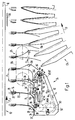
Die vorliegende Erfindung wird nun anhand der Zeichnung näher beschrieben. Es zeigen rein schematisch:
- Fig. 1 und 2
- in Ansicht eine Ausbildungsform der erfindungsgemässen Einrichtung zu zwei um einen halben Arbeitstakt voneinander verschiedenen Zeitpunkten;
- Fig. 3
- die Einrichtung gemäss den Fig. 1 und 2 in Seitenansicht;
- Fig. 4 und 5
- je einen Teil der als durchsichtig angenommenen Oeffnungseinrichtung in einem Schnitt entlang der Linie IV-IV bzw. V-V der Fig. 3;
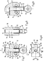
- Fig. 6 bis 9
- in Draufsicht bzw. in Schnitten entlang der entsprechenden Linien der Fig. 6 einen dem jeweils untenliegenden Produkteteil zugeordneten Greifer der Oeffnungseinrichtung;
- Fig. 10 bis 13
- in Draufsicht bzw. in Schnitten entlang den entsprechenden Linien der Fig. 10 einen dem jeweils obenliegenden Produkteteil zugeordneten Greifer der Oeffnungseinrichtung;
- Fig. 14 bis 18
- die in den Fig. 6-13 gezeigten Greifer beim Erfassen eines Druckereiprodukts mit obenliegendem vorstehendem Randabschnitt zu fünf verschiedenen aufeinanderfolgenden Zeitpunkten;
- Fig. 19 bis 23
- die Greifer beim Erfassen eines Druckereiprodukts mit untenliegendem vorstehendem Randabschnitt zu fünf verschiedenen aufeinanderfolgenden Zeitpunkten;
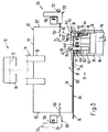
- Fig. 24
- eine Seitenansicht der Einrichtung gemäss Fig. 3 beim Oeffnen eines Druckereiproduktes mit untenliegendem vorstehendem Randabschnitt;
- Fig. 25 und 26
- in Ansicht eine weitere Ausbildungsform der erfindungsgemässen Vorrichtung zu zwei um einen halben Arbeitstakt verschiedenen Zeitpunkten beim Oeffnen von Druckereiprodukten mit nachlaufendem Endabschnitt;
- Fig. 27 und 28
- in Ansicht eine weitere Ausbildungsform der erfindungsgemässen Einrichtung zu zwei um einen halben Arbeitstakt verschiedenen Zeitpunkten beim Oeffnen von Druckereiprodukten mit vorlaufendem Endbereich;
- Fig. 29
- in Ansicht und stark vereinfacht eine weitere Ausbildungsform der erfindungsgemässen Einrichtung beim Oeffnen von Druckereiprodukten mit nachlaufendem Endbereich; und
- Fig. 30
- in Ansicht und stark vereinfacht eine der Ausführungsform gemäss Fig. 29 sehr ähnliche Ausbildungsform der erfindungsgemässen Einrichtung beim Oeffnen von Druckereiprodukten mit vorlaufendem Endbereich.
- 1 and 2
- in view a form of training of the inventive device at two times different from each other by half a work cycle;
- Fig. 3
- the device of Figures 1 and 2 in side view.
- 4 and 5
- each a part of the opening device assumed to be transparent in a section along the line IV-IV or VV of FIG. 3;
- 6 to 9
- In plan view or in sections along the corresponding lines in FIG. 6, a gripper of the opening device assigned to the respective lower product part;
- 10 to 13
- In plan view or in sections along the corresponding lines in FIG. 10, a gripper of the opening device assigned to the product part located at the top;
- 14 to 18
- the grippers shown in FIGS. 6-13 when gripping a printed product with the projecting edge section at the top at five different successive times;
- 19 to 23
- the grippers when grasping a printed product with the protruding edge section below at five different successive times;
- Fig. 24
- a side view of the device of Figure 3 when opening a printed product with the underlying projecting edge portion.
- 25 and 26
- in view a further embodiment of the device according to the invention to two different by half a work cycle Times when opening printed products with trailing end section;
- 27 and 28
- in view a further form of training of the device according to the invention at two times different by half a work cycle when opening printed products with a leading end area;
- Fig. 29
- in view and greatly simplified a further form of training of the inventive device when opening printed products with a trailing end area; and
- Fig. 30
- in view and greatly simplified, an embodiment of the device according to the invention which is very similar to the embodiment according to FIG. 29 when opening printed products with a leading end region.
Wie dies insbesondere aus den Fig. 1-3 hervorgeht, weist die Einrichtung eine Fördereinrichtung 10 allgemein bekannter Art mit in einem festen Abstand A hintereinander an einer strichpunktiert angedeuteten Förderkette 12 angeordnete Transportklammern 14 auf. Die Förderkette 12 ist in einem C-förmigen, gegen unten offenen und in horizontaler Richtung sich erstreckenden Kanal 16 geführt. Die in Förderrichtung F mit einer Fördergeschwindigkeit v kontinuierlich umlaufend angetriebenen Transportklammern 14 weisen ein in vertikaler Richtung gegen unten gerichtetes Klammermaul 18 auf, mit welchem sie ein gefaltetes Druckereiprodukt 20, vorzugsweise eine mehrblättrige Zeitung, Zeitschrift oder Teile davon, beim rechtwinklig zur Förderrichtung verlaufenden Falz 22 halten.As can be seen in particular from FIGS. 1-3, the device has a
Unterhalb der Fördereinrichtung 10 ist eine Oeffnungseinrichtung 24 vorhanden, die ein parallel zur Förderrichtung F verlaufendes Stützelement 26 aufweist, an dem die Druckereiprodukte 20 mit ihrem dem Falz 22 abgewandten Endbereich 28 flach anliegen. Die an den Transportklammern 14 frei hängenden Druckereiprodukte 20 werden beim Auflaufen auf das Stützelement 26, welches im vorliegenden Fall durch ein feststehendes Stützorgan 30 gebildet ist, nach hinten gebogen, wie dies aus den Fig. 1 und 2 deutlich hervorgeht.Below the conveying
Die Druckereiprodukte 20 sind aussermittig gefaltet. Der eine längere Produkteteil 32 weist im Endbereich 28 einen Randabschnitt 34 auf, der über den anderen kürzeren Produkteteil 36 vorsteht. Beim in den Fig. 1-3 gezeigten Beispiel werden die Druckereiprodukte 20 derart gefördert, dass der kürzere Produkteteil 36 vorlaufend ist und somit im Bereich des Stützorgans 30 der längere Produkteteil 32 mit dem Randabschnitt 34 obenliegend ist. Selbstverständlich ist in vertikaler Richtung die Oeffnungseinrichtung 24 nur soweit von der Fördereinrichtung 10 entfernt, dass die Druckereiprodukte 20 mit ihrem Endbereich 28 am Stützelement 26 anliegen können. Um verschiedenformatige Druckereiprodukte 20 verarbeiten zu können, ist die Oeffnungseinrichtung 24 in vertikaler Richtung verstellbar.The printed
Im folgenden wird nun die Oeffnungseinrichtung 24 unter Bezugnahme auf die Fig. 4-13 näher beschrieben. In den Fig. 1-3 sind die betreffenden Bezugszeichen nur soweit angegeben, als dies für das Verständnis dieser Figuren notwendig ist.In the following, the
Die Oeffnungseinrichtung 24 weist dem jeweils untenliegenden Produkteteil, im vorliegenden Fall dem kürzeren Produkteteil 36 zugeordnete erste Greifer 38 und dem jeweils obenliegenden Produkteteil, im vorliegenden Fall dem längern Produkteteil 32 zugeordnete zweite Greifer 40 auf. Mehrere erste Greifer 38 sind an einem endlosen ersten Zugorgan 42, vorzugsweise einer Kette in einem festen Abstand B angeordnet, der grösser ist als der Abstand A zwischen den Transportklammern 14 (Fig. 1). Ebenfalls sind mehrere zweite Greifer 40 an einem zweiten Zugorgan 44, ebenfalls vorzugsweise eine Kette, in einem festen Abstand C angeordnet, der etwa dem Abstand A zwischen den Transportklammern 14 entspricht. Die Zugorgane 42,44 laufen in zueinander parallelen Ebenen um und die aktiven Trume verlaufen nebeneinander und parallel zur Förderrichtung F. Die Zugorgane 42,44 sind je um drei entsprechend gleichachsig gelagerte Umlenkräder 46,46',48, 48',50,50' geführt, wobei die die aktiven Trume 42',44' begrenzenden Umlenkräder 46,48 und 46',48' im vorliegenden Fall den gleichen, Durchmesser aufweisen, hingegen das Umlenkrad 50, um welches der Rücktrum des ersten Zugorgans 42 geführt ist, einen grösseren Durchmesser aufweist als das Umlenkrad 50', um welches das Rücktrum des zweiten Zugorgans 44 läuft. Das Verhältnis dieser Durchmesser ist gleich dem Verhältnis des Abstandes B zum Abstand C. Da die Umlenkräder 50,50' drehfest auf einer gemeinsamen Antriebswelle 52 sitzen (Fig. 4 und 5), ist das Verhältnis der Umlaufgeschwindigkeit vl des ersten Zugorgans 42 und der ersten Greifer 38 zur Geschwindigkeit v2 des zweiten Zugorgans 44 und der zweiten Greifer 40 gleich dem Verhältnis zwischen dem Abstand B zwischen den ersten Greifern 38 und dem Abstand C zwischen den zweiten Greifern 40.The
Das eine Umlenkrad 50 oder 50' oder beide Umlenkräder 50, 50' können auf der Antriebswelle 52 in Drehrichtung verstellbar angeordnet sein, um die Phasenlage zwischen dem ersten und zweiten Zugorgan 42,44 und der Fördereinrichtung 10 einzustellen, so dass jeweils am gewünschten Ort, in Förderrichtung F gesehen im Anfangsbereich der aktiven Trume 42',44' je ein erster Greifer 38 und ein zweiter Greifer 40 sich nebeneinander befinden, wie dies Fig. 1 deutlich zeigt.One
Der erste Greifer 38 weist, wie dies insbesondere aus den Fig. 6-9 erkennbar ist, einen Greiferkörper 54 auf, durch welchen ein im wesentlichen zylinderförmiger Durchlass 56 verläuft. Die Achse 56' des Durchlasses 56 verläuft rechtwinklig zum ersten Zugorgan 42, welches in der Fig. 7 strichpunktiert angedeutet ist. Der Greiferkörper 54 ist mit dem ersten Zugorgan 42 mittels zwei Befestigungsbolzen 58 drehfest verbunden, welche den Greiferkörper 54 durch entsprechende Bohrungen 60 durchgreifen. Im Durchlass 56 ist ein Schaft 62 in Richtung der Achse 56' verschiebbar geführt. An seinem oberen Ende steht vom Schaft 62 eine blattartige Klemmzunge 64 ab, die mit einer am Greiferkörper 54 angeformten Klemmbacke 66 zusammenwirkt. Die Klemmzunge 64 und Klemmbacke 66 bilden ein Greifermaul 68, das bei der Oeffnungseinrichtung 24 gemäss den Fig. 1-4 in Förderrichtung gesehen nach vorne gerichtet ist. Wie dies weiter unten noch zu beschreiben ist, können die ersten Greifer 38 am Zugorgan 42 umgekehrt angeordnet sein, so dass das Greifermaul 68 entgegen der Förderrichtung F gerichtet ist. Die Klemmzunge 64 ist in Schliessrichtung mittels einer Druckfeder 70 vorgespannt, die den Schaft 62 umgreift und obernends an einer Schulter 72 des Greiferkörpers 54 und unternends an einer Gegenschulter 74 am Schaft 62 abgestützt ist. Die Schliessstellung des ersten Greifers 38 ist in der Fig. 9 gezeigt. In seinem unteren Endbereich ist am Schaft 62 eine Steuerrolle 76 um eine rechtwinklig zur Achse 56' und rechtwinklig zur Förderrichtung F verlaufende Achse 76' frei drehbar gelagert. Mittels einer Oeffnungskulisse 78 kann der Schaft 62 entgegen der Kraft der Druckfeder 70 rechtwinklig zur Förderrichtung F angehoben werden, so dass die Klemmzunge 64 in die in der Fig. 7 gezeigte Offenstellung überführbar ist. Mit 79 ist ein Anschlag bezeichnet, der das Greifermaul 68 begrenzt.As can be seen in particular from FIGS. 6-9, the
Der zweite Greifer 40 ist ähnlich aufgebaut wie der erste Greifer 38, wie dies insbesondere aus den Fig. 10-13 erkennbar ist. Ein Greiferkörper 80 weist ebenfalls einen im wesentlichen zylinderförmigen Durchlass 82 auf, dessen Achse mit 82' bezeichnet ist. Im Durchlass 82 ist ebenfalls ein Schaft 84 in Richtung der Achse 82' verschiebbar geführt. Im oberen Endbereich des Greiferkörpers 80 weist dieser eine feste Greiferbacke 86 auf, die in Förderrichtung F gesehen, nasenartig vorsteht. An die Greiferbacke 86 anschliessend ist im Greiferkörper 80 ein Führungsschlitz 88 ausgenommen, der in Richtung der Achse 82' verläuft und in welchem ein Klemmstift 90 geführt ist, der den Schaft 84 rechtwinklig zur Achse 82' durchdringt. Der Klemmstift 90 wirkt als bewegliche Greiferbacke mit der festen Greiferbacke 86 zusammen, diese bilden ein mit 92 bezeichnetes Greifermaul, das bei der Oeffnungseinrichtung 24 gemäss den Fig. 1-5 in Förderrichtung F gesehen im Bereich des förderwirksamen Trums 44' nach vorn gerichtet ist. Auch diese zweiten Greifer 40 können um 180° gekehrt am zweiten Zugorgan 44 angeordnet sein, so dass das Greifermaul 92 entgegen der Förderrichtung F gerichtet ist, wie dies weiter unten im Zusammenhang mit den Fig. 27 und 28 beschrieben ist.The
Am Klemmstift 90 stützt sich mit seinem oberen Ende eine als Druckfeder ausgebildete Schliessfeder 94 ab, die den Schaft 84 umgreift und unternends an einer Greiferkörperschulter 96 abgestützt ist. Die Schliessfeder 94 drängt den Klemmstift 90 in Schliessrichtung gegen die feste Greiferbacke 86. Die Schliessstellung des zweiten Greifers 40 ist in der Fig. 13 gezeigt.The upper end of the clamping
Im unteren Endbereich steht vom Schaft 84 in radialer Richtung eine Lagerwelle 98 ab, die eine langlochartige Oeffnung 100 im Greiferkörper 80 durchdringt und an welcher ausserhalb des Greiferkörpers 80 ebenfalls eine Steuerrolle 102 frei drehbar gelagert ist. Mittels einer weiteren mit 104 bezeichneten Oeffnungskulisse (Fig. 12) ist der Klemmstift 90 entgegen der Kraft der Schliessfeder 94 in die in der Fig. 11 gezeigte Offenstellung überführbar.In the lower end region, a bearing
Der Greiferkörper 80 ist mittels eines einzigen Befestigungsbolzens 106 (siehe auch Fig. 5) am zweiten Zugorgan 44 befestigt, wobei der Befestigungsbolzen 106 den Greiferkörper 80 durch eine Bohrung 108 durchdringt, deren Achse rechtwinklig zur Achse 82' und rechtwinklig zur Förderrichtung F verläuft. Die Bohrung 108 ist bezüglich dem Schwerpunkt des zweiten Greifers 40 in Förderrichtung F nach vorn versetzt, so dass der im zweiten Zugorgan 44 schwenkbar angeordnete zweite Greifer 40 im Bereich des aktiven Trums 44' die Tendenz hat, sich nach rückwärts, entgegen dem Uhrzeigersinn, zu verschwenken. Deshalb ist der Greiferkörper 80 in seinem unteren Endbereich 80' als Gleitschuh ausgebildet, der mit einer im Bereich des aktiven Trums 44' vorgesehenen Schwenkkulisse 110 zusammenwirkt.The
Die Form und Lage der mit dem ersten Greifer 38 zusammenwirkenden Oeffnungskulisse 78 und der auf den zweiten Greifer 40 einwirkenden Oeffnungskulisse 104 und Schwenkkulisse 110 sind aus den Fig. 1,2,4 und 5 entnehmbar. Die Schwenkkulisse 110 beginnt in Förderrichtung F gesehen dem Umlenkrad 46' nachfolgend und erstreckt sich in den Bereich des Umlenkrades 48'. Im Anfangsbereich dieser Schwenkkulisse 110 und oberhalb dieser ist die Oeffnungskulisse 104 für den zweiten Greifer 40 vorgesehen. Die Oeffnungskulisse 78 für den ersten Greifer 38 befindet sich benachbart zur Oeffnungskulisse 104.The shape and position of the
Am Ende der aktiven Trume 42',44' im Bereich der Umlenkräder 48,48' sind weitere Oeffnungskulissen 78',104' vorgesehen, um dort die ersten bzw. die zweiten Greifer 38,40 zu öffnen und die von ihnen gehaltenen Produkteteile 32,36 freizugeben.At the end of the active dreams 42 ', 44' in the area of the deflecting
Die Oeffnungseinrichtung 24 weist zwei über Traversen 114 miteinander verbundene Lagerschilder 116 auf, an welchen die Oeffnungskulissen 78,78',104,104' über die Welle der Umlenkräder 48,48' und die Schwenkkulisse 110 gegebenenfalls einstellbar befestigt sind. Wie dies Fig. 3 erkennen lässt, ist an den Traversen 114 eine Führungsschiene 118 abgestützt, in welcher die als Ketten ausgebildeten Zugorgane 42,44 im Bereich zwischen den Umlenkrädern 46,46' und 48,48' geführt sind. Von dieser Führungsschiene 118 und am, in der Fig. 3 linken Lagerschild 116 ist ebenfalls das als Stützblech 120 ausgebildete Stützorgan 30 befestigt. Dieses stützt die Druckereiprodukte 20, wie dies Fig. 3 zeigt, von der linken Seitenkante 122 her bis zu den ersten Greifern 38, die auf die Druckereiprodukte 20 benachbart zu ihrer rechten Seitenkante 122' einwirken. Das Stützblech 120 weist einen in Förderrichtung verlaufenden Schlitz auf, welcher von den zweiten Greifern 40 durchgriffen wird, wenn diese sich im Bereich des aktiven Trums 44' befinden.The
Das erste Zugorgan 42 ist im Bereich des aktiven Trums 42' derart geführt, dass die Klemmbacke 66 der ersten Greifer 38 mit der oberen Fläche des Stützblechs 120 etwa fluchtet. Die feste Greiferbacke 86 des zweiten Greifers 40 hat in vertialer Richtung gesehen einen grösseren Abstand zum Stützblech 120 als das obere Ende des ersten Greifers 38. Befindet sich aber der Klemmstift 90 des zweiten Greifers 40 in Offenstellung, ist dieser in vertikaler Richtung gesehen unter dem oberen Ende des ersten Greifers 38 angeordnet. Die Bewegungsbahn des Greifermauls 92 bei geschlossenem zweiten Greifer 40 verläuft deshalb oberhalb den ersten Greifern 38; dies immer im Bereich der aktiven Trume 42',44' gesehen.The
In vertikaler Richtung zwischen der Oeffnungseinrichtung 24 und der Fördereinrichtung 10 und seitlich ausserhalb dem Bereich der Druckereiprodukte 20 befindet sich eine Offenhalteeinrichtung 124 mit an einer Endloskette 126 angeordneten Offenhalteorganen 128. Diese weisen teleskopartig ausfahrbare Offenhaltestifte 130 auf, die beispielsweise über eine Kulissensteuerung 132 von der Seite her zwischen die mittels der Oeffnungseinrichtung 24 voneinander abgehobenen Produkteteile 32,36 im Bereich der Seitenkante 122' einführbar sind. Die Endloskette 126 ist in Umlaufrichtung U mit einer Geschwindigkeit, die der Fördergeschwindigkeit v der Fördereinrichtung 10 entspricht oder vorzugsweise mit einer grösseren Geschwindigkeit angetrieben, um die geöffneten Druckereiprodukte 20 beim Weitertransport offen zu halten und gegebenenfalls den jeweils vorlaufenden Produkteteil 36 noch weiter vom nachlaufenden Produkteteil 32 abzuheben.In the vertical direction between the opening
Der Oeffnungseinrichtung 24 ist eine Sammeleinrichtung 134 nachgeschaltet, die eine Vielzahl von Sammelstegen 136 aufweist, die um eine in den Fig. 1 und 2 nicht gezeigte gemeinsame Umlaufachse in Drehrichtung D umlaufen. Ein Sammelsteg 136 greift jeweils von unten in ein von der Oeffnungseinrichtung 24 geöffnetes und der Offenhalteeinrichtung 124 offen gehaltenes Druckereiprodukt 20 ein und nach dem Oeffnen der entsprechenden Transportklammer 14 mittels eines Oeffnungsorgans 138 fällt das betreffende Druckereiprodukt 20 rittlingsweise auf den betreffenden sattelförmigen Sammelsteg 136. Die Sammelstege 136 können Transportmittel aufweisen, um die abgelegten Druckereiprodukte 20 in ihrer Längsrichtung zu verschieben.The
Die Funktionsweise der Oeffnungseinrichtung 24 gemäss den Fig. 1-5 wird nun anhand der Fig. 14-18 beschrieben. Diese zeigen jeweils den ersten Greifer 38 und den zweiten Greifer 40 im Anfangsbereich der Schwenkkulisse 110 und im Bereich der Oeffnungskulissen 78 und 104 zu fünf aufeinanderfolgenden Zeitpunkten. Die in der Fig. 14 gezeigte Position nehmen die Greifer 38,40 im Anfangsbereich der aktiven Trume 42',44' ein, wie dies auch aus der Fig. 1 anhand der in Förderrichtung F gesehen hintersten Greifer 38,40 im Bereich der aktiven Trume 42',44' erkennbar ist. Die Klemmzunge 64 des ersten Greifers 38 befindet sich in Schliessstellung, wogegen der Klemmstift 90 des zweiten Greifers 40 bereits in Offenstellung überführt ist. Infolge der Einwirkung der Oeffnungskulisse 104 auf die Steuerrolle 102 und deren exzentrischen Lagerung bezüglich dem Befestigungsbolzen 106, nimmt der zweite Greifer 40 eine nach rückwärts geneigte Stellung ein. Der erste Greifer 38 holt nun infolge seiner Geschwindigkeit v1, die grösser ist als die Fördergeschwindigkeit v der Fördereinrichtung 10, das mit seinem Endbereich 28 auf dem Stützblech 120 gleitend aufliegende Druckereiprodukt 20 ein, so dass die Endkante des obenliegenden Produkteteils 32 am Anschlag 79 des Greiferkörpers 54 zur Anlage kommt, wie dies Fig. 15 zeigt. Nun wird die Klemmzunge 64 des ersten Greifers 38 infolge des Einwirkens der Oeffnungskulisse 78 in die Offenstellung überführt, wobei er den Randabschnitt 34 des obenliegenden Produkteteils 32 untergreift und mitanhebt, wie dies Fig. 16 zeigt. Gleichzeitig läuft der zweite Greifer 40 auf die Schwenkkulisse 110 auf, wodurch dieser im Uhrzeigersinn nach vorne verschwenkt wird, in eine Lage, in welcher die Achse 82' (vergleiche Fig. 10-13) etwa in vertikaler Richtung und somit etwa rechtwinklig zur Förderrichtung F verläuft. Infolge dieser Schwenkbewegung holt nun das Greifermaul 92 den Randabschnitt 34 ein, um diesen beim darauffolgenden Schliessen des zweiten Greifers 40 zwischen der Greiferbacke 86 und dem Klemmstift 90 einzuklemmen. Etwa gleichzeitig oder kurz danach wird die Klemmzunge 64 in die Schliesslage überführt, wodurch der untenliegende Produkteteil 36 bei seiner Endkante 32' festgeklemmt wird. Dabei ist zu bemerken, dass infolge der Relativgeschwindigkeit zwischen der Fördereinrichtung 10 und damit des Endbereichs 28 des betreffenden Druckereiprodukts 20 und dem ersten Greifer 38, die Endkante 36' des Produkteteils 36 an den Anschlag 79 zur Anlage gekommen ist, wie dies die Fig. 17 zeigt. Der erste Greifer 38 entfernt sich nun in Förderrichtung F immer mehr vom zweiten Greifer 40, wie dies aus der Fig. 18 und den Fig. 1 und 2 anhand der Greifer 38,40 im Mittelbereich der Oeffnungseinrichtung 24 erkennbar ist. Dabei wird der untenliegende Produkteteil 36 in Förderrichtung F gesehen ausgebaucht und vom nachlaufenden, obenliegenden Produkteteil 32 abgehoben. In die dadurch erzeugte Oeffnung entlang der Seitenkante 122' (vergleiche auch Fig. 3), wird nun ein Offenhaltestift 130 eingefahren. Im Bereich des Umlenkrades 48 wird dann der erste Greifer 38 infolge des Einwirkens der Oeffnungskulisse 78' geöffnet und der Produkteteil 36 freigegeben (Fig. 1). Sobald dann auch der betreffende zweite Greifer 40 durch das Umlenkrad 48' umgelenkt wird, wird dessen Greifermaul 92 unter Einwirkung der Oeffnungskulisse 104' geöffnet und der andere Produkteteil 32 freigegeben (Fig. 2).The operation of the
In den Fig. 19-23 ist derselbe Vorgang wie in den Fig. 14-18 gezeigt, wobei aber ein Druckereiprodukt 20 geöffnet wird, das von den Transportklammern 14 derart gehalten ist, dass bei auf dem Stützblech 120 gleitendem Endbereich 28 der längere Produkteteil 32 mit dem Randabschnitt 34 untenliegend ist. Zu diesem Zweck weist der erste Greifer 38 ein als Schwenknocken 140 ausgebildetes Biegeorgan 142 auf, wie dies aus der Fig. 3 und den Fig. 19-24 erkennbar ist. Der doppelarmige Schwenknocken 140 ist am in Förderrichtung F gesehen hinteren Befestigungsbolzen 58 des Greiferkörpers 54 schwenkbar gelagert und mittels einer Schwenkkulisse 144 (Fig. 3 und 24) aus einer Ruhelage (Fig. 21-23) in eine Arbeitslage, wie sie in den Fig. 19,20 und 24 gezeigt ist, verschwenkbar. Der Vollständigkeit halber sei erwähnt, dass die Schwenkkulisse 144 aus dem Einwirkbereich auf den Schwenknocken 140 verschoben werden kann und die Funktionsweise des ersten Greifers 38 genau dieselbe ist, wie sie weiter oben anhand der Fig. 1-18 beschrieben worden ist.19-23 is the same process as in Figs. 14-18, but a printed
Wie Fig. 19 im Vergleich zu Fig. 14 zeigt, wird durch den in Arbeitsstellung gebrachten Schwenknocken 140 ein Anschlag erzeugt, der bezüglich dem Anschlag 79 am Greiferkörper 54 vorlaufend ist. Dies verursacht eine Stosskraft auf die Endkante 32' des Randabschnittes 34 und infolge der schräg nach hinten abfallenden Vorderkante des sich in Arbeitsstellung befindenden Schwenknockens 140 wird der Randabschnitt 34 und ein daran anschliessender Bereich entlang der Seitenkante 122' nach unten gebogen und in Förderrichtung F nach vorn gedrückt. Dies hat ein Ausbauchen des untenliegenden Produkteteils 32 in Richtung gegen oben zur Folge, wie dies Fig. 20 und Fig. 24 zeigen. Diese Ausbauchung reicht vom ersten Greifer 38 bis in den Einwirkbereich des zweiten Greifers 40. Dadurch kann nun die vorgängig in eine Zwischenstellung zwischen der Klemm- und Offenstellung verbrachte Klemmzunge 64 den obenliegenden kürzeren Produkteteil 36 untergreifen, indem sie in die infolge der Ausbauchung des unteren Produkteteils 32 erzeugte Oeffnung 145 eingreift (Fig. 20,24). Durch das vollständige Anheben der Klemmzunge 64 in die Offenstellung ist der obenliegende Produkteteil 36 über den ersten Greifer 38 angehoben und der zweite Greifer 40 holt nun infolge seiner Schwenkbewegung im Uhrzeigersinn die Endkante 36' des Produkteteils 36 ein und kann diesen festklemmen (Fig. 21 und 22). Gleichzeitig wird der Schwenknocken 140 in seine Ruhelage verbracht, so dass die Endkante 32' des Produkteteils 32 an den Anschlag 79 des Greiferkörpers 54 zur Anlage kommt und der Randabschnitt 34 beim Ueberführen der Klemmzunge 64 in die Klemmlage vom ersten Greifer 38 festgeklemmt wird. Das Druckereiprodukt 20 wird nun nachfolgend auf dieselbe Art und Weise geöffnet, wie dies weiter oben beschrieben ist.As shown in FIG. 19 in comparison to FIG. 14, the
Die Fig. 25 und 26 zeigen eine Ausbildungsform der Oeffnungseinrichtung 24, die der in den Fig. 1-24 gezeigten Ausbildungsform sehr ähnlich ist. Zwei Unterschiede bestehen darin, dass das Umlenkrad 46 für das erste Zugorgan 42 in Förderrichtung F gesehen dem Umlenkrad 46' des zweiten Zugorgans 44 vorgeschaltet ist und somit sich die aktiven Trume 42',44' nur noch im Bereich zwischen dem Umlenkrad 46' und den gleichachsig gelagerten Umlenkrädern 48,48' überlappen, und dass die zweiten Greifer 40 am zweiten Zugorgan 44 nicht mehr schwenkbar, sondern fest angeordnet sind. Eine Schwenkkulisse für die zweiten Greifer 40 wird somit nicht mehr benötigt und die Oeffnungskulisse 78 für die ersten Greifer 38 und die Oeffnungskulisse 104 für die zweiten Greifer 40 befinden sich im Bereich des Umlenkrades 46'. In Förderrichtung F gesehen am Ende der Oeffnungseinrichtung 24 befinden sich die weiteren Oeffnungskulissen 78' und 104', um die Produkteteile 32,36 des geöffneten Druckereiprodukts 20 freizugeben. Die Fördereinrichtung 10, sowie die Greifer 38,40 sind ansonsten genau gleich ausgebildet, wie dies weiter oben beschrieben ist.25 and 26 show an embodiment of the
Die Funktionsweise der in den Fig. 25 und 26 gezeigten Ausbildungsform ist wie folgt: Die gefalteten Druckereiprodukte 20 werden von den Transportklammern 14 mit in horizontaler Richtung verlaufender Förderrichtung F hängend transportiert, und da der Endbereich 28 der Druckereiprodukte 20 auf dem als Stützblech 120 ausgebildeten Stützelement 26 gleitend aufliegt, sind die Druckereiprodukte 20 nach hinten gebogen. Der längere Produkteteil 32, mit dem über den kürzeren Produkteteil 36 vorstehenden Randabschnitt 34 ist somit obenliegend und in Förderrichtung F gesehen nachlaufend. Da die ersten Greifer 38 mit einer Geschwindigkeit v1 umlaufen, die grösser ist als die Fördergeschwindigkeit v der Fördereinrichtung 10, holt jeweils ein erster Greifer 38 ein Druckereiprodukt 20 im Bereich zwischen den Umlenkrädern 46 und 46' ein, dabei kommt die Endkante 32' an den Anschlag 79 zur Anlage (Fig. 25 und 26 erste Greifer 38, ganz links). Beim Umlenkrad 46' wird der erste Greifer 38 mittels der Oeffnungskulisse 78 geöffnet, indem die Klemmzunge 64 angehoben wird. Da diese den Randabschnitt 34 untergreift, wird der obenliegende Produkteteil 32 angehoben. Gleichzeitig schwenkt ein zweiter Greifer 40 infolge der Umlenkung um das Umlenkrad 46' in den Bereich des aktiven Trums 44' ein. Da das Greifermaul 92 in radialer Richtung gesehen über das zweite Zugorgan 44 vorsteht, holt der zweite Greifer 40 das Druckereiprodukt 20 ein und umgreift mit seiner Greiferbacke 86 und dem durch die Oeffnungskulisse 104 in die Qffenstellung überführten Klemmstift 90 den Randabschnitt 34 (siehe Fig. 26, Greifer 38,40 im Bereich des Umlenkrades 46'). Infolge der Relativgeschwindigkeit zwischen dem ersten Greifer 38 und der Fördereinrichtung 10 kommt nun die Endkante 36' des untenliegenden Produkteteils 36 an den Anschlag 79 des ersten Greifers 38 zur Anlage und wird beim Ablaufen des ersten Greifers 38 ab der Oeffnungskulisse 78 zwischen der Klemmbacke 66 und Klemmzunge 64 festgeklemmt. Etwa gleichzeitig oder kurz vorher, ist auch der zweite Greifer 40 von der betreffenden Oeffnungskulisse 104 abgelaufen, wodurch nun der Randabschnitt 34 im Greifermaul 92 festgehalten ist. Infolge der grösseren Geschwindigkeit v1 des ersten Greifers 38 bezüglich der Geschwindigkeit v2 der zweiten Greifer 40, wird nun das betreffende Druckereiprodukt 20 geöffnet, indem die Endkanten 32',36' in Förderrichtung F voneinander wegbewegt werden. Dadurch wird der vorlaufende und untenliegende Produkteteil 36 in Förderrichtung F ausgebaucht und schlussendlich vom ersten Greifer 38 freigegeben, wie dies Fig. 26, ganz rechts, zeigt. Sobald der zweite Greifer 40 in den Bereich der Oeffnungskulisse 104' beim Umlenkrad 48' gelangt, wird auch der nachlaufende, obenliegende Produkteteil 32 freigegeben. Die Weiterverarbeitung der Druckereiprodukte 20 kann auf genau gleiche Art und Weise erfolgen, wie dies anhand der Fig. 1-3 dargelegt ist.25 and 26 is as follows: The folded printed
Die Geschwindigkeit v2 der zweiten Greifer 40 entspricht annähernd der Fördergeschwindigkeit v der Fördereinrichtung 10.The speed v2 corresponds to the
Die Fig. 27 und 28 zeigen eine Ausbildungsform der Oeffnungseinrichtung 24 zum Oeffnen von Druckereiprodukten 20 mit in Förderrichtung F vorlaufendem Endbereich 28. Dabei ist das Stützelement 26 als der Oeffnungseinrichtung 24 vorgeschaltetes, endloses Stützband 146 ausgebildet, das an seinem förderwirksamen Ende um eine zum Umlenkrad 46' gleichachsige Umlenkwalze 148 umgelenkt ist. Das Stützband 146 ist mit einer Geschwindigkeit v3 angetrieben, die mindestens gleich gross, vorzugsweise aber grösser ist als die Fördergeschwindigkeit v der Fördereinrichtung 10. Die bei ihrem Falz 22 von den Transportklammern 14 mit etwa horizontaler Förderrichtung F transportierten Druckereiprodukte 20, liegen mit ihrem nach vorne gebogenen Endbereich 28 flach auf dem Stützband 146 auf. Der längere Produkteteil 32 mit dem Randabschnitt 34, der über den kürzeren Produkteteil 36 vorsteht, ist dabei obenliegend. Das erste Zugorgan 42 mit den ersten Greifern 38 ist um das Umlenkrad 46 umgelenkt, welches in Förderrichtung F gesehen dem Umlenkrad 46' für das zweite Zugorgan 44 und der Umlenkwalze 148 vorgeschaltet ist. Der Abstand B zwischen den ersten Greifern 38 ist gleich wie der Abstand A zwischen den Transportklammern 14 oder kleiner. Der aktive Trum 42' des ersten Zugorgans 42 verläuft vom Umlenkrad 46 zum Umlenkrad 48 und überlappt somit den aktiven Trum 44' des zweiten Zugorgans 44, der sich vom Umlenkrad 46' bis zum zum Umlenkrad 48 gleichachsigen Umlenkrad 48' erstreckt. Der Abstand C zwischen den zweiten Greifern 40 ist grösser als der Abstand B zwischen den ersten Greifern 38. Entsprechend grösser ist die Umlaufgeschwindigkeit v2 des zweiten Zugorgans 44 bezüglich der Umlaufgeschwindigkeit v1 der ersten Greifer 38. Diese unterschiedlichen Geschwindigkeiten v1,v2 werden dadurch erzeugt, dass das angetriebene Umlenkrad 50 für das erste Zugorgan 42 im Durchmesser entsprechend kleiner ist als das Umlenkrad 50' des zweiten Zugorgans 44. Der Vollständigkeit halber sei erwähnt, dass sich das Verhältnis der Geschwindigkeiten v1 zu v2 gleich verhält wie das Verhältnis der Abstände B zu C.27 and 28 show an embodiment of the
Die Greifer 38,40 sind genau gleich ausgebildet, wie dies weiter oben beschrieben und in den Fig. 6-13 dargestellt ist. Einzig das Greifermaul 68 der ersten Greifer 38 und Greifermaul 92 der zweiten Greifer 40 sind entgegen der Förderrichtung F gerichtet. Im übrigen entspricht der Aufbau der Oeffnungseinrichtung 24 den bereits weiter oben beschriebenen Ausbildungsformen. Für funktionsgleiche Teile werden die genau gleichen Bezugszeichen benützt und sie sind nur soweit in den Fig. 27 und 28 eingetragen, als dies für die nun folgende Darlegung der Funktionsweise notwendig ist.The
Im Bereich zwischen den Umlenkrädern 46 und 46' kommt jeweils ein Druckereiprodukt 20 mit seiner vorlaufenden Endkante 32' des Produkteteils 32 am Anschlag 79 des ersten Greifers 38 zur Anlage. Da die ersten Greifer 38 in diesem Bereich geschlossen sind, untergreift die Klemmzunge 64 den vorstehenden Randabschnitt 34 und hebt diesen an, wenn die Klemmzunge 64 infolge der Oeffnungskulisse 78 im Bereich des Umlenkrads 46' in die Offenstellung überführt wird (Fig. 28, erster Greifer 38 beim Umlenkrad 46'). Ein zweiter Greifer 40, der gerade bevor die Endkante 32' des Produkteteils 32 die Bewegungsbahn des radial äusseren Endes des zweiten Greifers 40 schneidet, gelangt in den Bereich des aktiven Trums 44' und wird mittels der strichpunktiert angedeuteten Schwenkkulisse 110 entgegen dem Uhrzeigersinn in Förderrichtung F gesehen nach rückwärts verschwenkt, um mit seinem geöffneten Greifermaul 92 den Randabschnitt 34 zu umgreifen. Beim Ablaufen ab der Oeffnungskulisse 104 wird der Klemmstift 90 angehoben und zwischen diesem und der Greiferbacke 86 der Randabschnitt 34 festgeklemmt. Beim Ablaufen des ersten Greifers 38 ab der entsprechenden Oeffnungskulisse 78 wird die Klemmzunge 64 in Schliessstellung überführt und klemmt dabei zwischen sich und der Klemmbacke 66 den Produkteteil 36 fest, der in das geöffnete Greifermaul 68 durch das Stützband 146 eingeschoben wurde. Infolge der unterschiedlichen Geschwindigkeiten v1,v2 zwischen den Greifern 38,40 wird nun der obenliegende Produkteteil 32 in Förderrichtung F vom untenliegenden Produkteteil 36 wegbewegt und dabei in eine gestrecktere Position überführt, wie dies insbesondere aus der Fig. 28 erkennbar ist. Der Produkteteil 36 behält dabei seine Biegung bei oder wird noch stärker gebogen, wenn die Geschwindigkeit v1 der ersten Greifer 38 kleiner ist als die Fördergeschwindigkeit v der Fördereinrichtung 10. Mit der Oeffnungskulisse 104' bzw. 78' werden zuerst der zweite Greifer 40 und zeitlich später der erste Greifer 38 im Bereich der Umlenkräder 48,48' geöffnet. Die Weiterverarbeitung der Druckereiprodukte kann auf die genau gleiche Art und Weise erfolgen, wie dies in den Fig. 1-3 gezeigt ist.In the area between the
Sind die ersten Greifer 38 mit einem Biegeorgan 142 ausgerüstet, so können mit der Oeffnungseinrichtung 24, wie sie in den Fig. 27 und 28 gezeigt ist, auch Druckereiprodukte 20 verarbeitet werden, die mit vorlaufendem Endbereich 28 und untenliegendem Randabschnitt 34 der Oeffnungseinrichtung 24 zugeführt werden. Das voneinander Abheben der beiden Produkteteile 32,36 erfolgt dann auf analoge Weise, wie dies in den Fig. 19-23 gezeigt und weiter oben beschrieben ist.If the
Die Klemmzunge 64 und das Biegeorgan 142 bilden Trennmittel, um jeweils die beiden Produkteteile 32,36 quer zur Förderrichtung F voneinander abzuheben. Die beiden Produkteteile 32,36 können dadurch jeweils sicher von den entsprechenden Greifern 38,40 erfasst werden.The clamping
Bei der Ausbildungsform gemäss Fig. 29 ist das Umlenkrad 46' für das zweite Zugorgan 44 mit den zweiten Greifern 40, in Förderrichtung F gesehen, dem Umlenkrad 46 für das erste Zugorgan 42 mit den ersten Greifern 38 vorgeschaltet. Im Bereich zwischen dem Umlenkrad 46 und den gleichachsig gelagerten, Umlenkrädern 48,48' am Ende der Oeffnungseinrichtung 24 überlappen sich die aktiven Trume 42' und 44'. Der Antrieb der Zugorgane 42,44 erfolgt auf gleiche Art und Weise wie dies weiter oben beschrieben ist über Umlenkräder 50,50' (vergleiche Fig. 25,26), die in der Fig. 29 nicht mehr gezeigt sind. Die Geschwindigkeit v1 der ersten Greifer 38 und der Abstand B zwischen diesen Greifern 38 sind entsprechend grösser als die Geschwindigkeit v2 der zweiten Greifer 40 bzw. der Abstand C zwischen diesen Greifern 40. Weiter ist die Geschwindigkeit v2 mindestens gleich gross wie, vorzugsweise aber grösser als die Fördergeschwindigkeit v der Transportklammern 14 der Fördereinrichtung 10; selbstverständlich sind die Abstände A und C entsprechend aufeinander abgestimmt.In the embodiment according to FIG. 29, the deflection wheel 46 'for the second pulling
Das Stützblech 120 weist beim Umlenkrad 46 eine in Förderrichtung F fallende Stufe 120' auf. Bis zu dieser Stufe 120' befindet sich die stützaktive Fläche des Stützblechs 120 oberhalb der Klemmstifte 90 der geöffneten zweiten Greifer 40, aber selbstverständlich unterhalb der Greiferbacke 86. In Förderrichtung F der Stufe 120' folgend fluchtet die stützaktive Fläche des Stützblechs 120 mit der Klemmbacke 66 der ersten Greifer 38. Auch bei dieser Ausbildungsform verläuft die Bewegungsbahn des Greifermauls 92 oberhalb den ersten Greifern 38.The
Der Aufbau der Greifer 38,40 ist genau gleich wie weiter oben beschrieben und in den Fig. 6 bis 13 dargestellt; wobei aber die zweiten Greifer 40 wie die ersten Greifer 38 fest, d.h. nicht verschwenkbar an den Zugorganen 42,44 angeordnet sind. Der besseren Uebersichtlichkeit halber sind in der Fig. 29 die weiter oben beschriebenen Oeffnungskulissen 78,78', 104,104' nicht dargestellt, ihre Lage geht aus der nun folgenden Funktionsbeschreibung der Einrichtung gemäss Fig. 19 hervor.The structure of the
Die bei ihrem Falz 22 von Transportklammern 14 etwa vertikal hängend gehaltenen Druckereiprodukte 20 werden mit ihrem Endbereich 28 auf dem Stützblech 120 aufliegend mit der Fördergeschwindigkeit v transportiert. Der längere Produkteteil 32 mit dem Randabschnitt 34 ist dabei bezüglich dem kürzeren Produkteteil 36 nachlaufend und obenliegend.The printed
Zwischen jeweils zwei Druckereiprodukten 20 schwenkt beim Umlenkrad 46' ein bereits geöffneter zweiter Greifer 40 in den aktiven Trum 44' ein und holt bis zu der Stufe 120' das vorlaufende Druckereiprodukt 20 ein, so dass der Randabschnitt 34 in das offene Greifermaul 92 gelangt. Der Klemmstift 90 untergreift den Randabschnitt 34 und hebt diesen beim Schliessen des zweiten Greifers 40 an. Der längere Produkteteil 32 wird dabei vom untenliegenden kürzeren Produkteteil 36 bereichsweise abgehoben und beim Ueberfahren der Stufe 120' fällt die Endkante 36' und der daran angrenzende Bereich des Produkteteils 36 unter Abheben vom obenliegenden, gehaltenen Produkteteil 32 nach unten auf das Stützblech 120. Nun holt ein geöffneter, um das Umlenkrad 46 in den Bereich des aktiven Trums 42' eingeschwenkter erster Greifer 38 den Produkteteil 32 ein, so dass dessen Endkante 32' am Anschlag 79 zur Anlage kommt. Beim nachfolgenden Absenken der Klemmzunge 64 gegen die Klemmbacke 66 in die Schliessstellung wird der untenliegende Produkteteil 36 festgeklemmt und in Förderrichtung F vom anderen Produkteteil 32 wegbewegt. Im Bereich der Umlenkräder 48,48' werden dann die Greifer 38,40 nacheinander geöffnet, so dass sie die voneinander abgehobenen Produkteteile 32,36 freigeben.Between each two printed
Die in der Fig. 30 gezeigte Oeffnungseinrichtung 24 ist in ihrem Aufbau der Oeffnungseinrichtung gemäss Fig. 29 äusserst ähnlich. Im folgenden wird nur noch auf die Unterschiede hingewiesen, soweit dies für das Verständnis notwendig ist. Die Umlenkräder 46,46',48,48',50,50' sind genau gleich angeordnet und die Zugorgane 42,44 gleich geführt wie in Fig. 29, die Greifermäuler 68,92 sind aber entgegen der Förderrichtung F nach hinten gerichtet. Die Geschwindigkeit v1 der zweiten Greifer 40 ist etwa gleich gross wie, vorzugsweise aber kleiner als die Fördergeschwindigkeit v. Die Geschwindigkeit v1 des ersten Greifers 38 ist kleiner als die Geschwindigkeit v2. Entsprechend ist auch der Abstand A zwischen den Transportklammern 14 gleich gross oder grösser als der Abstand C zwischen den zweiten Greifern 40, und der Abstand B zwischen den ersten Greifern 38 kleiner als der Abstand C.The structure of the
Das Stützband 146 ist mit einer Geschwindigkeit in Förderrichtung F angetrieben, die mindestens gleich gross wie, vorzugsweise grösser als die Fördergeschwindigkeit v ist, um die darauf mit ihrem Endbereich 28 aufliegenden Druckereiprodukte 20 mit vorlaufendem Randabschnitt 34 den zweiten Greifern 40 zuzuführen. Das Stützband 146, das in einem Spalt im Stützblech 120 verläuft und mit seinem förderaktiven oberen Trum über das Stützblech 120 vorsteht, ist um eine zum Umlenkrad 46 gleichachsig gelagerte, in der Fig. 30 nicht gezeigte Walze geführt, so dass es vor dem Umlenkrad 46' beginnend bis zum Umlenkrad 46 förderund stützaktiv ist.The
Die Zugorgane 42,44 sind derart synchronisiert, dass in einem Bereich, beim Umlenkrad 46 beginnend bis nach der fallenden Stufe 120' im Stützblech 120, jeweils der erste Greifer 38 dem entsprechenden zweiten Greifer 40 vorläuft und dann vor dem Erreichen der Umlenkräder 48,48' der zweite Greifer 40 den ersten Greifer 38 überholt.The
Die Einrichtung gemäss Fig. 30 funktioniert wie folgt. Die Druckereiprodukte 20 werden von den Transportklammern 14 beim Falz 20 etwa in vertikaler Richtung hängend gefördert. Der längere Produkteteil 32 ist gegenüber dem kürzeren Produkteteil 36 jeweils vorlaufend, so dass infolge des Stützbandes 146 der Endbereich 28 vorlaufend und der Randabschnitt 34 obenliegend ist. Beim Umlenkrad 46' schwenkt jeweils ein mittels der nicht gezeigten Oeffnungskulisse geöffneter zweiter Greifer 40 zwischen jeweils zwei Druckereiprodukte 20 ein. Da der Endbereich 28 mit grösserer Geschwindigkeit als der zweite Greifer 40 bewegt wird, läuft der Randabschnitt 34 in das geöffnete Greifermaul 92 ein, so dass beim Schliessen des Greifers 40 beim Umlenkrad 46 der vom Klemmstift 90 untergriffene Randabschnitt 34 angehoben und im Greifermaul 92 festgeklemmt wird. Nach dem Ueberfahren der Stufe 120' fällt der untenliegende kürzere Produkteteil 36 mit seinem an die vorlaufende Endkante 36' angrenzenden Abschnitt vom obenliegenden Produkteteil 32 weiter weg und gelangt in das Maul 68 des ersten Greifers 38 etwa, wenn dieser vom entsprechenden zweiten Greifer 40 überholt wird. Durch Absenken der Klemmzunge 64 wird der Produkteteil 32 festgeklemmt und dann werden infolge der Relativgeschwindigkeit zwischen den Greifern 38,40 die Produkteteile 32,36 weiter voneinander in Förderrichtung F abgehoben. Selbstverständlich verläuft die Bewegungsbahn des geschlossenen Greifermauls 92 oberhalb des ersten Greifers 38. Bei den Umlenkrädern 48,48' werden dann die Greifer 38,40 für die Freigabe der voneinander abhobenen Produkteteile 32,36 geöffnet.30 works as follows. The printed
Bei den in den Fig. 29 und 30 gezeigten Ausbildungsformen der Oeffnungseinrichtung 24 bilden der Klemmstift 90 und die Stufe 120' im Stützblech 120 die Trennmittel, um die aneinander anliegenden Produkteteile 32,36 quer zur Förderrichtung voneinander abzuheben.In the embodiment of the
Selbstverständlich können die Greifer eine unterschiedliche Ausbildungsform aufweisen. Es ist auch denkbar, diese nicht umlaufend, sondern hin- und herbewegend anzutreiben.Of course, the grippers can have a different design. It is also conceivable not to drive them around, but to move them back and forth.
Die Zugorgane 42,44 können auch individuell angetrieben sein. Dies ermöglicht eine eifnache Synchronisation und Anpassung an unterschiedliche Formate der zu öffnenden Druckereiprodukte.The
Je nach der Anordnung der Oeffnungseinrichtung 24 bezüglich der Fördereinrichtung 10 können die Druckereiprodukte links, mittig, oder rechts geöffnet werden. Es ist auch denkbar, zwei gleiche Oeffnungseinrichtungen 24 nebeneinander anzuordnen, so dass die Druckereiprodukte in zwei Bereichen gleichzeitig geöffnet werden.Depending on the arrangement of the
Claims (18)
Applications Claiming Priority (2)
| Application Number | Priority Date | Filing Date | Title |
|---|---|---|---|
| CH111692 | 1992-04-06 | ||
| CH1116/92 | 1992-04-06 |
Publications (2)
| Publication Number | Publication Date |
|---|---|
| EP0564812A1 true EP0564812A1 (en) | 1993-10-13 |
| EP0564812B1 EP0564812B1 (en) | 1997-05-28 |
Family
ID=4202864
Family Applications (1)
| Application Number | Title | Priority Date | Filing Date |
|---|---|---|---|
| EP93103235A Expired - Lifetime EP0564812B1 (en) | 1992-04-06 | 1993-03-01 | Method and device for opening folded printing products |
Country Status (7)
| Country | Link |
|---|---|
| US (2) | US5354043A (en) |
| EP (1) | EP0564812B1 (en) |
| JP (1) | JP2700287B2 (en) |
| AT (1) | ATE153628T1 (en) |
| CA (1) | CA2093400C (en) |
| DE (1) | DE59306556D1 (en) |
| ES (1) | ES2101889T3 (en) |
Cited By (1)
| Publication number | Priority date | Publication date | Assignee | Title |
|---|---|---|---|---|
| EP0709326A1 (en) | 1994-10-28 | 1996-05-01 | Ferag AG | Method and device for marking folded printed produkts on an inner page |
Families Citing this family (15)
| Publication number | Priority date | Publication date | Assignee | Title |
|---|---|---|---|---|
| DK0600216T3 (en) * | 1992-12-04 | 1996-06-03 | Ferag Ag | Method and device for opening folded printing products |
| ES2115831T3 (en) * | 1993-10-08 | 1998-07-01 | Ferag Ag | DEVICE TO OPEN AND TRANSPORT PRINTED PRODUCTS. |
| DE59405899D1 (en) * | 1993-12-21 | 1998-06-10 | Grapha Holding Ag | Process for loading multi-sheet printed sheets with inserts collected into printed products |
| EP0718225A3 (en) * | 1994-12-22 | 1996-12-11 | Grapha Holding Ag | Device for feeding a collecting section of a gathering and stitching machine |
| DE59503157D1 (en) * | 1995-01-13 | 1998-09-17 | Ferag Ag | Device for opening printed products and device for processing printed products |
| US5655760A (en) * | 1996-05-14 | 1997-08-12 | Heidelberg Finishing Systems Inc. | Collator with air assistance |
| DK0831045T3 (en) * | 1996-09-06 | 2002-02-11 | Ferag Ag | Method and apparatus for opening flexible flat products |
| US5758871A (en) * | 1996-09-25 | 1998-06-02 | Heidelberg Finishing Systems, Inc. | Signature collating apparatus |
| WO2001064561A1 (en) * | 2000-03-03 | 2001-09-07 | Ferag Ag | Device for processing flat, flexible objects with one or more pieces |
| WO2002057167A1 (en) * | 2001-01-19 | 2002-07-25 | Ferag Ag | Device for receiving printed products |
| ATE394332T1 (en) * | 2003-12-22 | 2008-05-15 | Ferag Ag | METHOD AND DEVICE FOR STABILIZING AND POSITIONING FLAT OBJECTS |
| US20100200363A1 (en) * | 2007-07-30 | 2010-08-12 | Ferag Ag | System for combining groups of flat objects |
| AU2009253665B2 (en) * | 2008-05-26 | 2014-10-09 | Ferag Ag | Device and method for inserting flat objects into a folded printed product |
| CH701468A1 (en) * | 2009-07-13 | 2011-01-14 | Ferag Ag | Method and apparatus for opening printing products. |
| CH703248A1 (en) | 2010-05-31 | 2011-12-15 | Ferag Ag | Device and method for opening of printing products. |
Citations (8)
| Publication number | Priority date | Publication date | Assignee | Title |
|---|---|---|---|---|
| US2817513A (en) * | 1954-06-29 | 1957-12-24 | Kenneth T Moser | Sheet separating means for collating machine |
| DE1024530B (en) * | 1954-11-18 | 1958-02-20 | Rudolf Hepp | Method and device for lifting from one another folded paper layers with a protruding edge for the purpose of nesting the paper layers |
| GB1095733A (en) * | 1964-12-14 | 1967-12-20 | Leipziger Buchbindereimaschine | Method of and apparatus for opening folded sheets |
| FR1530715A (en) * | 1965-11-24 | 1968-06-28 | Ferag Ag | Installation for opening a product comprising several sheets of paper and inserting a supplement |
| DE1817030A1 (en) * | 1968-02-02 | 1969-08-07 | Ferag Ag | Method for opening multi-sheet, folded printed matter, in particular newspapers, as well as a device for carrying out the method |
| GB2066790A (en) * | 1980-01-08 | 1981-07-15 | Ferag Ag | Method and apparatus for opening folded bound or stitched multi-sheet products especially printed products |
| EP0095603A1 (en) * | 1982-06-01 | 1983-12-07 | Ferag AG | Device for collecting folded printing sheets |
| EP0208081A1 (en) * | 1985-07-01 | 1987-01-14 | Ferag AG | Method and device for opening eccentrically folded printing products |
Family Cites Families (8)
| Publication number | Priority date | Publication date | Assignee | Title |
|---|---|---|---|---|
| AT296932B (en) * | 1965-11-24 | 1972-03-10 | Ferag Ag | Device for inserting supplements into folded printed matter |
| CH667620A5 (en) * | 1985-07-01 | 1988-10-31 | Ferag Ag | METHOD AND DEVICE FOR COLLECTING FOLDED PRINTED SHEETS. |
| CH667859A5 (en) * | 1985-07-19 | 1988-11-15 | Ferag Ag | Folded printed item opening mechanism - has holders securing items at position along fold to prevent turning |
| EP0352421A3 (en) * | 1988-07-26 | 1990-08-29 | R. R. Donnelley & Sons Company | Apparatus and method for individually printing signatures during delivery to a binding line conveyor |
| DE59200946D1 (en) * | 1991-06-10 | 1995-01-26 | Ferag Ag | Method and device for opening and placing folded printed products on a saddle-shaped support. |
| ES2079727T3 (en) * | 1991-06-10 | 1996-01-16 | Ferag Ag | PROCEDURE AND DEVICE FOR THE TREATMENT OF PRINTED PRODUCTS. |
| DE59201323D1 (en) * | 1991-07-11 | 1995-03-16 | Ferag Ag | Method and device for opening flexible, off-center folded products. |
| US5277413A (en) * | 1991-12-19 | 1994-01-11 | Grapha-Holding Ag | Rotary signature gathering apparatus with sheet stop |
-
1993
- 1993-03-01 ES ES93103235T patent/ES2101889T3/en not_active Expired - Lifetime
- 1993-03-01 DE DE59306556T patent/DE59306556D1/en not_active Expired - Lifetime
- 1993-03-01 EP EP93103235A patent/EP0564812B1/en not_active Expired - Lifetime
- 1993-03-01 AT AT93103235T patent/ATE153628T1/en not_active IP Right Cessation
- 1993-03-24 JP JP5089358A patent/JP2700287B2/en not_active Expired - Lifetime
- 1993-04-05 US US08/044,782 patent/US5354043A/en not_active Expired - Lifetime
- 1993-04-05 CA CA002093400A patent/CA2093400C/en not_active Expired - Fee Related
-
1994
- 1994-10-07 US US08/319,942 patent/US5474286A/en not_active Expired - Lifetime
Patent Citations (8)
| Publication number | Priority date | Publication date | Assignee | Title |
|---|---|---|---|---|
| US2817513A (en) * | 1954-06-29 | 1957-12-24 | Kenneth T Moser | Sheet separating means for collating machine |
| DE1024530B (en) * | 1954-11-18 | 1958-02-20 | Rudolf Hepp | Method and device for lifting from one another folded paper layers with a protruding edge for the purpose of nesting the paper layers |
| GB1095733A (en) * | 1964-12-14 | 1967-12-20 | Leipziger Buchbindereimaschine | Method of and apparatus for opening folded sheets |
| FR1530715A (en) * | 1965-11-24 | 1968-06-28 | Ferag Ag | Installation for opening a product comprising several sheets of paper and inserting a supplement |
| DE1817030A1 (en) * | 1968-02-02 | 1969-08-07 | Ferag Ag | Method for opening multi-sheet, folded printed matter, in particular newspapers, as well as a device for carrying out the method |
| GB2066790A (en) * | 1980-01-08 | 1981-07-15 | Ferag Ag | Method and apparatus for opening folded bound or stitched multi-sheet products especially printed products |
| EP0095603A1 (en) * | 1982-06-01 | 1983-12-07 | Ferag AG | Device for collecting folded printing sheets |
| EP0208081A1 (en) * | 1985-07-01 | 1987-01-14 | Ferag AG | Method and device for opening eccentrically folded printing products |
Cited By (2)
| Publication number | Priority date | Publication date | Assignee | Title |
|---|---|---|---|---|
| EP0709326A1 (en) | 1994-10-28 | 1996-05-01 | Ferag AG | Method and device for marking folded printed produkts on an inner page |
| US5596932A (en) * | 1994-10-28 | 1997-01-28 | Ferag Ag | Process and apparatus for the typographical labeling of folded printed products on an inner side |
Also Published As
| Publication number | Publication date |
|---|---|
| JP2700287B2 (en) | 1998-01-19 |
| ATE153628T1 (en) | 1997-06-15 |
| ES2101889T3 (en) | 1997-07-16 |
| US5474286A (en) | 1995-12-12 |
| CA2093400A1 (en) | 1993-10-07 |
| EP0564812B1 (en) | 1997-05-28 |
| JPH069148A (en) | 1994-01-18 |
| CA2093400C (en) | 1999-01-19 |
| US5354043A (en) | 1994-10-11 |
| DE59306556D1 (en) | 1997-07-03 |
Similar Documents
| Publication | Publication Date | Title |
|---|---|---|
| EP0346578B1 (en) | Device for assembling, collating and inserting printing products | |
| EP0564812B1 (en) | Method and device for opening folded printing products | |
| EP0208081B1 (en) | Method and device for opening eccentrically folded printing products | |
| EP0551601B1 (en) | Method and device for feeding particularly folded printed products to a further processing station | |
| EP0330868B1 (en) | Process and device for conveying away printed products fed in a shingled formation | |
| CH630583A5 (en) | DEVICE FOR MOVING AWAY OF FLAT PRODUCTS INCLUDING IN A DOMESTIC FLOW, IN PARTICULAR PRINTED PRODUCTS. | |
| EP0305671B1 (en) | Conveyor for prints, and use of the conveyor | |
| EP0522319B1 (en) | Method and device for opening flexible articles folded off-centre | |
| EP0518063B1 (en) | Method and apparatus for opening and placing folded printed products on a saddle-shaped support | |
| DE3306815C2 (en) | DEVICE FOR TRANSPORTING FLAT PRODUCTS INCLUDED IN A DANDEL INFORMATION, IN PARTICULAR PRINTED PRODUCTS | |
| EP0600216B1 (en) | Method and device for opening folded printing products | |
| AT396908B (en) | DEVICE FOR PROCESSING PRINTED PRODUCTS | |
| DE2058606A1 (en) | Method and device for the lateral alignment of sheets, in particular in a printing press | |
| EP0300171B1 (en) | Device for transporting flat products, in particular printed products | |
| EP0218804B1 (en) | Device for taking over and transferring folded sheets from a conveyor | |
| DE19833851A1 (en) | Method and device for creating a rotated product stream with a corner gripper | |
| EP0518064B1 (en) | Method and apparatus for handling of printed products | |
| CH683913A5 (en) | Feed for continuously accumulating fabrics, in particular printed products. | |
| EP0647582A1 (en) | Device for opening and further conveying printed products | |
| EP0300170B1 (en) | Method and device for separating products in overlapping streams, in particular printed products | |
| EP1072546B1 (en) | Conveyer for collating and processing printed sheets | |
| DE1561141B2 (en) | DEVICE FOR INSERTING INSERTS INTO FOLDED PRINT PRODUCTS | |
| EP1411011B1 (en) | Device for transferring products to a conveying device | |
| EP0699611B1 (en) | Conveying device for feeding flat printed products to a processing machine | |
| CH690576A5 (en) | Apparatus for processing printing products. |
Legal Events
| Date | Code | Title | Description |
|---|---|---|---|
| PUAI | Public reference made under article 153(3) epc to a published international application that has entered the european phase |
Free format text: ORIGINAL CODE: 0009012 |
|
| 17P | Request for examination filed |
Effective date: 19930713 |
|
| AK | Designated contracting states |
Kind code of ref document: A1 Designated state(s): AT CH DE ES FR GB IT LI NL SE |
|
| GRAG | Despatch of communication of intention to grant |
Free format text: ORIGINAL CODE: EPIDOS AGRA |
|
| GRAH | Despatch of communication of intention to grant a patent |
Free format text: ORIGINAL CODE: EPIDOS IGRA |
|
| 17Q | First examination report despatched |
Effective date: 19960808 |
|
| GRAH | Despatch of communication of intention to grant a patent |
Free format text: ORIGINAL CODE: EPIDOS IGRA |
|
| GRAA | (expected) grant |
Free format text: ORIGINAL CODE: 0009210 |
|
| ITF | It: translation for a ep patent filed |
Owner name: 0508;03RMFSOCIETA' ITALIANA BREVETTI S.P |
|
| AK | Designated contracting states |
Kind code of ref document: B1 Designated state(s): AT CH DE ES FR GB IT LI NL SE |
|
| REF | Corresponds to: |
Ref document number: 153628 Country of ref document: AT Date of ref document: 19970615 Kind code of ref document: T |
|
| REG | Reference to a national code |
Ref country code: CH Ref legal event code: NV Representative=s name: PATENTANWAELTE SCHAAD, BALASS, MENZL & PARTNER AG Ref country code: CH Ref legal event code: EP |
|
| GBT | Gb: translation of ep patent filed (gb section 77(6)(a)/1977) |
Effective date: 19970528 |
|
| REF | Corresponds to: |
Ref document number: 59306556 Country of ref document: DE Date of ref document: 19970703 |
|
| REG | Reference to a national code |
Ref country code: ES Ref legal event code: FG2A Ref document number: 2101889 Country of ref document: ES Kind code of ref document: T3 |
|
| ET | Fr: translation filed | ||
| PLBE | No opposition filed within time limit |
Free format text: ORIGINAL CODE: 0009261 |
|
| STAA | Information on the status of an ep patent application or granted ep patent |
Free format text: STATUS: NO OPPOSITION FILED WITHIN TIME LIMIT |
|
| 26N | No opposition filed | ||
| PGFP | Annual fee paid to national office [announced via postgrant information from national office to epo] |
Ref country code: NL Payment date: 20000223 Year of fee payment: 8 |
|
| PGFP | Annual fee paid to national office [announced via postgrant information from national office to epo] |
Ref country code: ES Payment date: 20000321 Year of fee payment: 8 |
|
| PGFP | Annual fee paid to national office [announced via postgrant information from national office to epo] |
Ref country code: AT Payment date: 20010226 Year of fee payment: 9 |
|
| PG25 | Lapsed in a contracting state [announced via postgrant information from national office to epo] |
Ref country code: ES Free format text: LAPSE BECAUSE OF NON-PAYMENT OF DUE FEES Effective date: 20010302 |
|
| PGFP | Annual fee paid to national office [announced via postgrant information from national office to epo] |
Ref country code: FR Payment date: 20010313 Year of fee payment: 9 |
|
| PG25 | Lapsed in a contracting state [announced via postgrant information from national office to epo] |
Ref country code: NL Free format text: LAPSE BECAUSE OF NON-PAYMENT OF DUE FEES Effective date: 20011001 |
|
| NLV4 | Nl: lapsed or anulled due to non-payment of the annual fee |
Effective date: 20011001 |
|
| REG | Reference to a national code |
Ref country code: GB Ref legal event code: IF02 |
|
| PG25 | Lapsed in a contracting state [announced via postgrant information from national office to epo] |
Ref country code: AT Free format text: LAPSE BECAUSE OF NON-PAYMENT OF DUE FEES Effective date: 20020301 |
|
| PG25 | Lapsed in a contracting state [announced via postgrant information from national office to epo] |
Ref country code: FR Free format text: LAPSE BECAUSE OF NON-PAYMENT OF DUE FEES Effective date: 20021129 |
|
| REG | Reference to a national code |
Ref country code: FR Ref legal event code: ST |
|
| REG | Reference to a national code |
Ref country code: ES Ref legal event code: FD2A Effective date: 20030203 |
|
| REG | Reference to a national code |
Ref country code: CH Ref legal event code: PFA Owner name: FERAG AG Free format text: FERAG AG##CH-8340 HINWIL (CH) -TRANSFER TO- FERAG AG#PATENTABTEILUNG Z. H. MARKUS FELIX ZUERICHSTRASSE 74#8340 HINWIL (CH) |
|
| PG25 | Lapsed in a contracting state [announced via postgrant information from national office to epo] |
Ref country code: IT Free format text: LAPSE BECAUSE OF NON-PAYMENT OF DUE FEES Effective date: 20050301 |
|
| PGFP | Annual fee paid to national office [announced via postgrant information from national office to epo] |
Ref country code: GB Payment date: 20090325 Year of fee payment: 17 |
|
| GBPC | Gb: european patent ceased through non-payment of renewal fee |
Effective date: 20100301 |
|
| PGFP | Annual fee paid to national office [announced via postgrant information from national office to epo] |
Ref country code: SE Payment date: 20100312 Year of fee payment: 18 |
|
| PG25 | Lapsed in a contracting state [announced via postgrant information from national office to epo] |
Ref country code: GB Free format text: LAPSE BECAUSE OF NON-PAYMENT OF DUE FEES Effective date: 20100301 |
|
| REG | Reference to a national code |
Ref country code: SE Ref legal event code: EUG |
|
| PGFP | Annual fee paid to national office [announced via postgrant information from national office to epo] |
Ref country code: DE Payment date: 20120323 Year of fee payment: 20 |
|
| PGFP | Annual fee paid to national office [announced via postgrant information from national office to epo] |
Ref country code: CH Payment date: 20120606 Year of fee payment: 20 |
|
| REG | Reference to a national code |
Ref country code: DE Ref legal event code: R071 Ref document number: 59306556 Country of ref document: DE |
|
| REG | Reference to a national code |
Ref country code: DE Ref legal event code: R071 Ref document number: 59306556 Country of ref document: DE |
|
| REG | Reference to a national code |
Ref country code: CH Ref legal event code: PL |
|
| PG25 | Lapsed in a contracting state [announced via postgrant information from national office to epo] |
Ref country code: SE Free format text: LAPSE BECAUSE OF NON-PAYMENT OF DUE FEES Effective date: 20110302 Ref country code: DE Free format text: LAPSE BECAUSE OF EXPIRATION OF PROTECTION Effective date: 20130302 |