EP0300171A1 - Dispositif de transport pour produits plats, en particulier des produits imprimés - Google Patents
Dispositif de transport pour produits plats, en particulier des produits imprimés Download PDFInfo
- Publication number
- EP0300171A1 EP0300171A1 EP88108587A EP88108587A EP0300171A1 EP 0300171 A1 EP0300171 A1 EP 0300171A1 EP 88108587 A EP88108587 A EP 88108587A EP 88108587 A EP88108587 A EP 88108587A EP 0300171 A1 EP0300171 A1 EP 0300171A1
- Authority
- EP
- European Patent Office
- Prior art keywords
- clamping
- conveying direction
- transporter according
- product
- plunger
- Prior art date
- Legal status (The legal status is an assumption and is not a legal conclusion. Google has not performed a legal analysis and makes no representation as to the accuracy of the status listed.)
- Granted
Links
Images


Classifications
-
- B—PERFORMING OPERATIONS; TRANSPORTING
- B65—CONVEYING; PACKING; STORING; HANDLING THIN OR FILAMENTARY MATERIAL
- B65H—HANDLING THIN OR FILAMENTARY MATERIAL, e.g. SHEETS, WEBS, CABLES
- B65H29/00—Delivering or advancing articles from machines; Advancing articles to or into piles
- B65H29/66—Advancing articles in overlapping streams
- B65H29/669—Advancing articles in overlapping streams ending an overlapping stream
-
- B—PERFORMING OPERATIONS; TRANSPORTING
- B65—CONVEYING; PACKING; STORING; HANDLING THIN OR FILAMENTARY MATERIAL
- B65H—HANDLING THIN OR FILAMENTARY MATERIAL, e.g. SHEETS, WEBS, CABLES
- B65H29/00—Delivering or advancing articles from machines; Advancing articles to or into piles
- B65H29/003—Delivering or advancing articles from machines; Advancing articles to or into piles by grippers
-
- B—PERFORMING OPERATIONS; TRANSPORTING
- B65—CONVEYING; PACKING; STORING; HANDLING THIN OR FILAMENTARY MATERIAL
- B65H—HANDLING THIN OR FILAMENTARY MATERIAL, e.g. SHEETS, WEBS, CABLES
- B65H2301/00—Handling processes for sheets or webs
- B65H2301/40—Type of handling process
- B65H2301/44—Moving, forwarding, guiding material
- B65H2301/447—Moving, forwarding, guiding material transferring material between transport devices
- B65H2301/4471—Grippers, e.g. moved in paths enclosing an area
-
- B—PERFORMING OPERATIONS; TRANSPORTING
- B65—CONVEYING; PACKING; STORING; HANDLING THIN OR FILAMENTARY MATERIAL
- B65H—HANDLING THIN OR FILAMENTARY MATERIAL, e.g. SHEETS, WEBS, CABLES
- B65H2301/00—Handling processes for sheets or webs
- B65H2301/40—Type of handling process
- B65H2301/44—Moving, forwarding, guiding material
- B65H2301/447—Moving, forwarding, guiding material transferring material between transport devices
- B65H2301/4473—Belts, endless moving elements on which the material is in surface contact
- B65H2301/44732—Belts, endless moving elements on which the material is in surface contact transporting articles in overlapping stream
Definitions
- the present invention relates to a conveyor with a plurality of individually controllable grippers, which are arranged one behind the other in the conveying direction on at least one rotatingly driven pulling element.
- a transporter for such scale formations is known, the gripper of which grasp the products at the leading edges, which are formed here by the folds, and with the same arrangement, ie the mutual position of the products and the before the running edge remains intact, transport it further.
- the conveying direction of the transporter runs from bottom to top and across the level of the products to be detected.
- the first product of the scale formation is gripped and raised by a gripper on the uncovered leading edge, so that the leading edge of the next product to be detected is released; the scale formation is peeled, so to speak, and the covered, leading edges are exposed.
- the grippers must be arranged on the traction element so as to be pivotable about an axis running transversely to the conveying direction and must be aligned at least in the takeover area so that the clamping jaws and the clamping fingers can grip the products without injuring them.
- the object of the present invention is to provide a named conveyor according to the preamble of claim 1, in which the products can be detected on the leading edge in the scale formation without exposing them, even if the leading edge is the Flower acts.
- the clamping finger itself creates the space to the leading edge of the product to be detected by the Be rich of the preceding product, which raises the leading edge to be detected covered.
- the gripper grasps the products of the scale formation from below, and also the leading edges of products that can be fanned out can be detected because fanning out is prevented by the dead weight.
- pivoting of the grippers relative to the traction element is not necessary, since the two above-mentioned conveying directions are aligned.
- the closing movement of the clamping finger is preferably a pivoting movement which is opposite to the conveying direction, and the apex of the path of movement of the clamping finger is higher than the path of movement of the clamping jaw. It is thereby achieved in a simple manner that the product is grasped from above and at the leading edge and at the same time the preceding product is raised in the area which covers the leading edge of the tracing edge, so that there is space for the problem-free grasping of the leading edge becomes free.
- a particularly simple drive arrangement for the clamping finger is formed by a crank mechanism with an oscillating crank loop, the clamping finger being arranged on the coupling.
- a trajectory for the clamping finger can be reached which runs almost perpendicular to the plane of the products to be detected towards the end of the closing movement.
- the products are only subjected to pressure and not to shear, which reduces the risk of injury.
- the crank mechanism is preferably driven by means of a plunger which is slidably mounted on a carrier, the toothing of which engages with a toothed pinion which is connected in a rotationally fixed manner to the crank.
- the longitudinal movement of the ram is easily converted to the desired pivoting movement of the clamping finger.
- two synchronously rotating traction elements are arranged in parallel and at a distance from one another, the products being detected at the end regions of their leading edge on both sides.
- the space between the two traction elements is therefore free and is available for feeders or away conveyors.
- the plunger in the takeover area is preferably controlled by means of a link, with a relief link simultaneously releasing the clamping member from its clamping position.
- the scenes are only necessary in the takeover area and can be carried out with simple means.
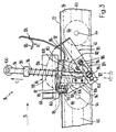
- a takeover area A of the transporter 10 is shown in FIG. 1.
- the flat products 12 fed in by a feed conveyor 11 indicated only by an arrow in scale formation S are picked up and conveyed further by the transporter 10.
- the products 12 are superimposed like roof tiles in the scale formation S, each product 12 resting on the next one.
- a trailing edge of each product 12 is formed by a fold 13, around which the products 12 are folded, while a leading edge 13 'is formed by the fanned out, the fold 13 distal ends of the products 12.
- the products 12 are primarily folded printed products, such as magazines or newspapers, or parts thereof.
- only one gripper 14 is shown in FIG. 1 in five different positions I to V, which it takes one after the other as seen in the conveying direction B. The function of the gripper 14 and the meaning of the positions I to V will be discussed below.
- a rotating shaft 18 of a rotatably mounted deflection roller 20 is arranged on a frame 16, which is only partially shown.
- a continuously drivable endless belt 22 is guided around the deflection roller 20.
- a conveyor-effective strand 24 of this endless belt 22 moves in the conveying direction B on a support plate 26 fastened to the frame 16.
- a link frame 28, 28 ' is also attached, on which two backdrops, a relief backdrop 30 and a closing backdrop 32 are arranged.
- the scenes 30, 32 extend approximately over the take-over area A.
- the relief scene 30 runs essentially parallel to the support plate 26.
- a drive-up nose 34 which is bent towards the plate 26, precedes the parallel scenery part.
- a retracting or extending nose 36, 38 are integrally formed in the beginning or end area of the closing link 32.
- a pressure roller 40 is shown in broken lines.
- two guide rollers 20, 20 ' are shown rotatably mounted on the rotating shaft 18 arranged on the frame 16.
- the pressure roller 40 is rotatably mounted on a pivot pin 42 which is fastened to a pressure lever 44.
- the pressure lever 44 is in a known manner and Way pivotally mounted on the frame 16; this is not shown in the figure.
- the link frame 28 consists of a frame plate 46, a bracket 48 welded to it and a diagonal support 50, and a relief link carrier 52 welded to the bracket 48.
- the closing link 32 is fastened to the end of the bracket 48 and the relief link 30 to the relief link carrier 52, on which an anti-skid device 54 is arranged.
- the setting frame 28 ' is of the same design as the setting frame 28. It is obvious that the setting frame 28, 28' does not necessarily have to be a welded construction.
- the frame plate 46 is arranged on a channel 56. This has the shape of a C, the opening of which is directed upwards.
- a traction element designed as a conveyor chain 58 is displaceably guided in channel 56.
- the conveyor chain 58 consists of a plurality of conveyor chain links 62 arranged one behind the other in the conveying direction B and connected to one another by means of tabs 60.
- Each conveyor chain link 62 has two guide wheels 66 rotatably mounted on two screw bolts 64 (see also FIG. 3).
- a neck 68 is arranged on each conveyor chain link 62 and protrudes through the opening of the channel 56.
- a guide roller 70 is rotatably mounted on the neck 68 at the level of the opening of the channel 56.
- the guide roller 70 ensures the centering of the conveyor chain links 62 in the channel 56 and can be supported on thickenings 72 of the channel 56 on both sides of the opening.
- the guide wheels 66 run on the bottom of the channel 56. You can but are also supported on the thickenings 72. Since the conveyor chain 58 is designed to be endless in itself, this is particularly the case with the neck 68 hanging down in the return of the conveyor chain 58.
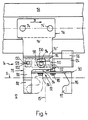
- a carrier 76 of the gripper 14 is fastened by means of two fastening bolts 74, 74 '(cf. also FIG. 4).
- the carrier 76 is integrally L-shaped, the horizontal leg 76 ', as described above, is attached to the conveyor chain link 62, while the second leg 76 ⁇ is directed parallel to the end faces of the channel 56 downwards.
- the leg 76 ⁇ is in any case so far from the channel 56 that they never come into contact with each other.
- the leg 76 ⁇ consists of an equilateral hexagonal sheet whose downward-facing side edges, which converge at an acute angle, from a lower edge which is approximately parallel to the bottom of the channel 56 and whose height is limited.
- a jaw 78 is welded to the leg 76 ⁇ .
- the clamping jaw 78 consists of a C-shaped sheet which is open at the bottom and on which, viewed in the conveying direction B, a clamping jaw projection 80 is formed at the trailing end. It can be seen particularly well from FIGS. 2 and 4 that the clamping jaw projection 80 extends into the area of the scale formation S and is provided there with a jaw support 82. The products 12 come to rest on the jaw support 82, as described below.
- a guide plate 84 is arranged at the lower end of the leg 76 ⁇ .
- a pivot pin 86 is attached, about the axis 88 of a clamping finger 90 is pivotally mounted.
- a drive arrangement 92 likewise arranged on the leg 76 ⁇ acts on the clamping finger 90.
- the drive arrangement 92 consists of a crank mechanism and a plunger 94 acting thereon.
- the plunger 94 is slidably guided in the clamping jaw 78 and in the guide plate 84 approximately transversely to the conveying direction B.
- a compression spring 96 which is supported on one end on the clamping jaw 78 and on the other end on a plunger collar 98 fastened to the plunger.
- a follower roller 100 is rotatably mounted thereon.
- a stop washer 102 is attached to it. In the plunger position shown in FIG.
- a slide plane 104 is milled on the plunger 94 and is mounted on a slide shoe 106.
- the slide shoe 106 is made of a plastic and is fastened to the leg 76 ⁇ by means of screws. It prevents the ram 94 from rotating about its longitudinal axis.
- a toothing 108 is arranged on the plunger 94 opposite the sliding plane 104. This toothing 108 interacts with a pinion 110.
- a crank 112 in the form of a disk is rotatably connected to the pinion 110.
- the pinion 110 and the crank 112 are rotatably mounted on a shaft 114 which is arranged on the leg 76 ⁇ .
- the clamping finger 90 is formed in one piece. Its end remote from the pivot pin 86 is bent and forms a clamping finger jaw 116. In the central region, the clamping finger 90 is rotatably mounted on the crank by means of a shaft 118. The clamping finger 90 consequently forms a coupling 120 of the crank mechanism, the crank loop 122, which is designed as an elongated hole, is mounted on the pivot pin 86.
- the clamping finger jaw 116 is cut into a V-shape, so that the protruding free end 117, with the gripper 14 closed, shown in broken lines, can rest on the jaw support 82 of the clamping jaw 78 or on the top of the detected product 12.
- the free end 117 is arrow-shaped when viewed in side view.
- a clamping member 124 is pivotally mounted on the part of the clamping jaw 78 that leads in the direction of conveyance B and is bent downward.
- a sliding bend 126 is formed on the clamping member 124, and on the other hand, the clamping member 124 is slidably mounted on a guide pin 128 arranged on the clamping jaw 78.
- the clamping member 124 is provided at this end with an incision 130, the side edges of which slide on the guide pin 128 (cf. in particular FIG. 4).
- a further compression spring 132 supported on the clamping jaw 78 and arranged around the guide pin 128 acts on the clamping member 124 in the region of the incision 130.
- the plunger 94 penetrates the clamping member 124 in a clamping opening 134.
- the gripper 14 is shown in an open position, while a closed position is indicated by dash-dotted lines.
- the diameter of the clamping opening 134 is only slightly larger than the diameter of the plunger 94.
- the clamping finger 124 is again moved counterclockwise, as already described above.
- the plunger moves from the position shown in broken lines in the direction of the arrow C until the stop disk 102 on the guide plate 84 strikes back to the original position, with the crank 112 being driven clockwise and the free end 117 of the clamping finger jaw 116 moving back along the same movement path 136 into the open position. Since this free movement of the plunger 94 back into its original position occurs with considerable accelerations, the plunger movement is advantageously controlled, as is described below.
- Grippers 14 are arranged one behind the other in the conveying direction B on the rotating conveyor chain 58. Each gripper 14 detects a product 12 in the takeover area A and transports it further.
- the grippers 14 are arranged at the same intervals, as shown in FIG. 1. It should be noted, however, that the same gripper 14 is shown in five different positions I to V in FIG. 1. In order to maintain a better overview, the further grippers 14 have been omitted.
- the products 12 of the scale formation S fed by means of the feed conveyor 11 come to rest on the conveying strand 24 of the endless belt 22, 22 '.
- the endless belt 22 moves in the conveying direction B at the same speed as the conveyor chain 58.
- the gripper 14 is guided in the open position to the takeover area A, the jaw support 82 coming from below to the leading edge 13 'of the product 12 to be detected.
- the sliding bend 126 runs onto the drive-in nose 34, which has the consequence that the clamping member 124 (see also FIG. 3 in each case) moves in the counterclockwise direction and the plunger 94 is released.
- the following role 100 comes first on the drive-in nose 36 and then on the closing link 32 to the system (position I), which means that, due to the movement of the gripper 14 in the conveying direction B, the plunger 94 is moved downward in the direction of the arrow E, which leads to the closing movement of the clamping finger 90 Consequence. Since the clamping finger jaw 116, as described above, moves upwards and counter to the conveying direction B, the preceding product 12 is raised in the region in which it covers the leading edge 13 'to be detected (position II).
- the leading edge 13 ' is exposed, and by the downward movement towards the end of the movement path 136, the leading edge 13' of the product 12 to be detected is clamped between the clamping finger 90 and the clamping jaw 78 (position III).
- the jaw support 82 prevents injury to the product 12.
- position II it is shown how the clamping finger 90 lifts the preceding product 12.
- the pressure roller 40 presses on the middle area of the products 12 and clamps them between the conveying strand 24 and itself.
- the grasped product 12 is still clamped and then the sliding bend 126 runs from the relief link 30, whereby the plunger is jammed in the closed position.
- the closing link 32 with the extension lug 38 releases the following roller 100 (position IV).
- the plunger cannot move upwards because it is held in position by the clamping member 124, as shown in positions IV and V.
- a relief link 30 and a closing link 32 are preferably arranged in such a way that the follower clip 100 first comes into contact with the closing link 32 and then the clamping member 124 is released by means of the relief link 30. Subsequent enlargement of the distance between the support plate 26 and the closing link 32 results in a slow, continuous opening of the clamping finger 90.
- the pressure roller 40 can also be replaced by a concentricity. This consists, for example, of a second pressure roller 40 and an endless belt arranged between the two pressure rollers and rotating around them.
- the pivot pin 86 can also be attached to the plunger 94. As a result, the movement of the clamping finger 90 against the conveying direction B is faster.
- the carriers 76 can also be pivotally attached to the traction element, the pivot axis being perpendicular to the conveying direction B and in a plane parallel to the support plate 26.
- the scenes 30, 32 are advantageously arranged in a stationary manner, the closing link 32 being spring-mounted on the link frame 28, 28 '.
- the spring force between the link frame 28, 28 'and the closing link 32 must then be selected so that first the plunger against the force of the compression spring 96th is moved downward, and when the clamping finger 90 has reached the closed position, the closing link 32 is pushed upward.
- products 12 of various thicknesses can be gripped with the gripper 14 without having to adjust the closing link 32.
- the drive arrangement does not necessarily have to include a crank drive. Any other drive arrangement is conceivable which forces the clamping finger jaw 116 to have a path of movement similar to the path of movement 136.
- the preceding and the preceding product 12 is raised by the clamping finger 90 (cf. FIG. 1).
Applications Claiming Priority (2)
| Application Number | Priority Date | Filing Date | Title |
|---|---|---|---|
| CH275387 | 1987-07-21 | ||
| CH2753/87 | 1987-07-21 |
Publications (2)
| Publication Number | Publication Date |
|---|---|
| EP0300171A1 true EP0300171A1 (fr) | 1989-01-25 |
| EP0300171B1 EP0300171B1 (fr) | 1990-12-19 |
Family
ID=4240837
Family Applications (1)
| Application Number | Title | Priority Date | Filing Date |
|---|---|---|---|
| EP88108587A Expired - Lifetime EP0300171B1 (fr) | 1987-07-21 | 1988-05-28 | Dispositif de transport pour produits plats, en particulier des produits imprimés |
Country Status (4)
| Country | Link |
|---|---|
| US (1) | US4905986A (fr) |
| EP (1) | EP0300171B1 (fr) |
| JP (1) | JP2542238B2 (fr) |
| DE (1) | DE3861306D1 (fr) |
Families Citing this family (12)
| Publication number | Priority date | Publication date | Assignee | Title |
|---|---|---|---|---|
| US5165422A (en) * | 1989-01-23 | 1992-11-24 | Broad Jr Robert L | Apparatus for assembling a contraceptive device |
| SE9103290L (sv) * | 1991-11-07 | 1993-05-08 | Wamag Idab Ab | Foerfarande och anordning foer att oeppna en sjaelvstaengande gripare paa en griparetransportoer |
| DE4223232A1 (de) * | 1992-07-15 | 1994-01-20 | Heidelberger Druckmasch Ag | Vorrichtung zur Steuerung des Öffnungszeitpunktes von Greifern eines Bogenauslegers einer bogenverarbeitenden Maschine |
| ES2100421T3 (es) * | 1993-01-14 | 1997-06-16 | Ferag Ag | Dispositivo para alimentar articulos planos a un dispositivo de manipulacion de productos de imprenta. |
| ES2086853T3 (es) * | 1993-01-14 | 1996-07-01 | Ferag Ag | Dispositivo para transportar productos planos. |
| US5501443A (en) * | 1994-12-02 | 1996-03-26 | Heidelberger Druckmaschinen Ag | Device for the release of folded products |
| US5697752A (en) * | 1995-07-13 | 1997-12-16 | Progressive Tool & Industries Company | Overhead transfer clamp actuator and linkage |
| DE19642117A1 (de) * | 1996-10-12 | 1998-04-16 | Koenig & Bauer Albert Ag | Klemmzange für Endlosförderer |
| US6067883A (en) * | 1997-08-13 | 2000-05-30 | Heidelberger Druckmaschinen Ag | Method and apparatus for providing positive control of a printable medium in a printing system |
| WO2001081216A1 (fr) * | 2000-04-20 | 2001-11-01 | Ferag Ag | Dispositif permettant d"acheminer des objets plats |
| US7527261B2 (en) * | 2006-07-13 | 2009-05-05 | Lockheed Martin Corporation | Mailpiece container for stacking mixed mail and method for stacking mail therein |
| DE102018218384A1 (de) * | 2018-10-26 | 2020-04-30 | Multivac Sepp Haggenmüller Se & Co. Kg | Verpackungsmaschine mit transportkette |
Citations (2)
| Publication number | Priority date | Publication date | Assignee | Title |
|---|---|---|---|---|
| GB1185606A (en) * | 1967-07-21 | 1970-03-25 | Ferag Ag | Improvements in or relating to Conveyer Apparatus |
| FR2272936A1 (fr) * | 1974-05-28 | 1975-12-26 | Ferag Ag |
Family Cites Families (7)
| Publication number | Priority date | Publication date | Assignee | Title |
|---|---|---|---|---|
| CH546197A (de) * | 1971-09-14 | 1974-02-28 | Fehr & Reist Ag | Wendefoerderer fuer flaechengebilde, insbesondere druckprodukte. |
| CH610276A5 (fr) * | 1975-05-20 | 1979-04-12 | Ferag Ag | |
| CH630583A5 (de) * | 1978-06-30 | 1982-06-30 | Ferag Ag | Vorrichtung zum wegfoerdern von in einem schuppenstrom anfallenden flaechigen erzeugnissen, insbesondere druckprodukten. |
| EP0095602B1 (fr) * | 1982-06-02 | 1986-01-29 | Ferag AG | Dispositif pour le transport de produits planes de papier alimentés en continu |
| US4505378A (en) * | 1982-12-17 | 1985-03-19 | Rockwell International Corporation | Conveyor pocket gripping apparatus |
| WO1986003476A1 (fr) * | 1984-12-07 | 1986-06-19 | Rockwell International Corporation | Systemes transporteurs |
| US4746007A (en) * | 1986-02-20 | 1988-05-24 | Quipp Incorporated | Single gripper conveyor system |
-
1988
- 1988-05-28 DE DE8888108587T patent/DE3861306D1/de not_active Expired - Lifetime
- 1988-05-28 EP EP88108587A patent/EP0300171B1/fr not_active Expired - Lifetime
- 1988-07-06 JP JP63168645A patent/JP2542238B2/ja not_active Expired - Lifetime
- 1988-07-15 US US07/219,206 patent/US4905986A/en not_active Expired - Fee Related
Patent Citations (2)
| Publication number | Priority date | Publication date | Assignee | Title |
|---|---|---|---|---|
| GB1185606A (en) * | 1967-07-21 | 1970-03-25 | Ferag Ag | Improvements in or relating to Conveyer Apparatus |
| FR2272936A1 (fr) * | 1974-05-28 | 1975-12-26 | Ferag Ag |
Also Published As
| Publication number | Publication date |
|---|---|
| DE3861306D1 (de) | 1991-01-31 |
| EP0300171B1 (fr) | 1990-12-19 |
| JPS6434847A (en) | 1989-02-06 |
| US4905986A (en) | 1990-03-06 |
| JP2542238B2 (ja) | 1996-10-09 |
Similar Documents
| Publication | Publication Date | Title |
|---|---|---|
| DE2922450A1 (de) | Vorrichtung zum wegfoerdern von in einem schuppenstrom anfallenden flaechigen erzeugnissen, insbesondere druckprodukten | |
| EP0330868B1 (fr) | Procédé et dispositif d'évacuation de produits imprimés, qui sont amenés en formation en écailles | |
| EP0346578B1 (fr) | Dispositif pour assembler, collationner et insérer des produits imprimés | |
| DE3508416C2 (fr) | ||
| EP0208081A1 (fr) | Procédé et dispositif d'ouverture pour imprimés pliés de manière excentrée | |
| CH637091A5 (de) | Vorrichtung zum zufuehren von in einem schuppenstrom anfallenden flaechigen erzeugnissen, insbesondere druckprodukten, zu einem transporteur. | |
| EP0095602B1 (fr) | Dispositif pour le transport de produits planes de papier alimentés en continu | |
| EP0522319B1 (fr) | Procédé et dispositif pour ouvrir des articles flexible pliés hors du centre | |
| CH649972A5 (de) | Vorrichtung zum uebereinanderlegen von einzelnen flaechigen erzeugnissen, insbesondere druckprodukten. | |
| EP0564812B1 (fr) | Procédé et dispositif pour ouvrir des produits d'imprimerie pliés | |
| EP0300171B1 (fr) | Dispositif de transport pour produits plats, en particulier des produits imprimés | |
| DE3130945A1 (de) | "vorrichtung zum herausloesen von mittels eines foerderers gefoerderten biegsamen, flaechigen erzeugnissen, insbesondere druckprodukten, aus dem foerderstrom" | |
| EP0600216B1 (fr) | Procédé et dispositif pour ouvrir des produits d'imprimerie pliés | |
| DE3306815A1 (de) | Vorrichtung zum transportieren von in einer schuppenformation anfallenden flaechigen erzeugnissen, insbesondere druckprodukten | |
| DE3023533A1 (de) | Vorrichtung zum ablegen von bogen in einem stapel | |
| DE2058606A1 (de) | Verfahren und Vorrichtung zum seitlichen Ausrichten von Blaettern,insbesondere bei einer Druckpresse | |
| EP0218804B1 (fr) | Dispositif pour reprendre et transférer des feuilles pliées d'un dispositif de transport | |
| EP0242702A1 (fr) | Procédé et dispositif pour tourner des objets plats | |
| EP0518064B1 (fr) | Procédé et appareil pour la manutention de produits imprimés | |
| EP0647582A1 (fr) | Dispositif pour ouvrir et transporter des produits imprimés | |
| EP0300170B1 (fr) | Procédé et dispositif de séparation de produits se chevauchant, en particulier de produits imprimés | |
| WO2000024660A1 (fr) | Procede et dispositif d'alimentation en imprimes | |
| DE1786046A1 (de) | Verfahren zum Stapeln von Signaturen und Vorrichtung zur Durchfuehrung des Verfahrens | |
| EP0062785B1 (fr) | Dispositif pour dévier du courant de transport des articles plats et flexibles, en particulier des articles imprimés | |
| DE2815599C2 (de) | Vorrichtung zum Falten von Wäschestücken |
Legal Events
| Date | Code | Title | Description |
|---|---|---|---|
| PUAI | Public reference made under article 153(3) epc to a published international application that has entered the european phase |
Free format text: ORIGINAL CODE: 0009012 |
|
| AK | Designated contracting states |
Kind code of ref document: A1 Designated state(s): CH DE LI SE |
|
| 17P | Request for examination filed |
Effective date: 19881224 |
|
| 17Q | First examination report despatched |
Effective date: 19900522 |
|
| GRAA | (expected) grant |
Free format text: ORIGINAL CODE: 0009210 |
|
| AK | Designated contracting states |
Kind code of ref document: B1 Designated state(s): CH DE LI SE |
|
| REF | Corresponds to: |
Ref document number: 3861306 Country of ref document: DE Date of ref document: 19910131 |
|
| PLBE | No opposition filed within time limit |
Free format text: ORIGINAL CODE: 0009261 |
|
| STAA | Information on the status of an ep patent application or granted ep patent |
Free format text: STATUS: NO OPPOSITION FILED WITHIN TIME LIMIT |
|
| 26N | No opposition filed | ||
| EAL | Se: european patent in force in sweden |
Ref document number: 88108587.2 |
|
| PGFP | Annual fee paid to national office [announced via postgrant information from national office to epo] |
Ref country code: SE Payment date: 19960425 Year of fee payment: 9 |
|
| PG25 | Lapsed in a contracting state [announced via postgrant information from national office to epo] |
Ref country code: SE Effective date: 19970529 |
|
| EUG | Se: european patent has lapsed |
Ref document number: 88108587.2 |
|
| REG | Reference to a national code |
Ref country code: CH Ref legal event code: PFA Owner name: FERAG AG Free format text: FERAG AG#ZUERICHSTRASSE 74#8340 HINWIL (CH) -TRANSFER TO- FERAG AG#PATENTABTEILUNG Z. H. MARKUS FELIX ZUERICHSTRASSE 74#8340 HINWIL (CH) |
|
| PGFP | Annual fee paid to national office [announced via postgrant information from national office to epo] |
Ref country code: CH Payment date: 20070418 Year of fee payment: 20 |
|
| PGFP | Annual fee paid to national office [announced via postgrant information from national office to epo] |
Ref country code: DE Payment date: 20070522 Year of fee payment: 20 |
|
| REG | Reference to a national code |
Ref country code: CH Ref legal event code: PL |