EP0299539B1 - Apparatus for sleeving damaged tubes of a nuclear steam generator - Google Patents
Apparatus for sleeving damaged tubes of a nuclear steam generator Download PDFInfo
- Publication number
- EP0299539B1 EP0299539B1 EP88111679A EP88111679A EP0299539B1 EP 0299539 B1 EP0299539 B1 EP 0299539B1 EP 88111679 A EP88111679 A EP 88111679A EP 88111679 A EP88111679 A EP 88111679A EP 0299539 B1 EP0299539 B1 EP 0299539B1
- Authority
- EP
- European Patent Office
- Prior art keywords
- sleeve
- turret
- blank
- lifting means
- sleeve blank
- Prior art date
- Legal status (The legal status is an assumption and is not a legal conclusion. Google has not performed a legal analysis and makes no representation as to the accuracy of the status listed.)
- Expired - Lifetime
Links
- 238000003780 insertion Methods 0.000 claims description 19
- 230000037431 insertion Effects 0.000 description 13
- 238000000034 method Methods 0.000 description 4
- 230000008569 process Effects 0.000 description 4
- 229910001098 inconels 690 Inorganic materials 0.000 description 3
- 238000003754 machining Methods 0.000 description 3
- 230000002285 radioactive effect Effects 0.000 description 2
- 230000008439 repair process Effects 0.000 description 2
- 206010073306 Exposure to radiation Diseases 0.000 description 1
- 230000009471 action Effects 0.000 description 1
- 229910045601 alloy Inorganic materials 0.000 description 1
- 239000000956 alloy Substances 0.000 description 1
- 230000000712 assembly Effects 0.000 description 1
- 238000000429 assembly Methods 0.000 description 1
- 239000004020 conductor Substances 0.000 description 1
- 230000008878 coupling Effects 0.000 description 1
- 238000010168 coupling process Methods 0.000 description 1
- 238000005859 coupling reaction Methods 0.000 description 1
- 238000010586 diagram Methods 0.000 description 1
- 239000012530 fluid Substances 0.000 description 1
- 229910001026 inconel Inorganic materials 0.000 description 1
- 229910001055 inconels 600 Inorganic materials 0.000 description 1
- 229910001119 inconels 625 Inorganic materials 0.000 description 1
- 238000009434 installation Methods 0.000 description 1
- 230000007246 mechanism Effects 0.000 description 1
- 238000012986 modification Methods 0.000 description 1
- 230000004048 modification Effects 0.000 description 1
- 230000002093 peripheral effect Effects 0.000 description 1
- 230000011664 signaling Effects 0.000 description 1
- 125000006850 spacer group Chemical group 0.000 description 1
Images


Classifications
-
- B—PERFORMING OPERATIONS; TRANSPORTING
- B23—MACHINE TOOLS; METAL-WORKING NOT OTHERWISE PROVIDED FOR
- B23P—METAL-WORKING NOT OTHERWISE PROVIDED FOR; COMBINED OPERATIONS; UNIVERSAL MACHINE TOOLS
- B23P19/00—Machines for simply fitting together or separating metal parts or objects, or metal and non-metal parts, whether or not involving some deformation; Tools or devices therefor so far as not provided for in other classes
- B23P19/02—Machines for simply fitting together or separating metal parts or objects, or metal and non-metal parts, whether or not involving some deformation; Tools or devices therefor so far as not provided for in other classes for connecting objects by press fit or for detaching same
-
- F—MECHANICAL ENGINEERING; LIGHTING; HEATING; WEAPONS; BLASTING
- F28—HEAT EXCHANGE IN GENERAL
- F28F—DETAILS OF HEAT-EXCHANGE AND HEAT-TRANSFER APPARATUS, OF GENERAL APPLICATION
- F28F11/00—Arrangements for sealing leaky tubes and conduits
- F28F11/02—Arrangements for sealing leaky tubes and conduits using obturating elements, e.g. washers, inserted and operated independently of each other
-
- B—PERFORMING OPERATIONS; TRANSPORTING
- B23—MACHINE TOOLS; METAL-WORKING NOT OTHERWISE PROVIDED FOR
- B23P—METAL-WORKING NOT OTHERWISE PROVIDED FOR; COMBINED OPERATIONS; UNIVERSAL MACHINE TOOLS
- B23P19/00—Machines for simply fitting together or separating metal parts or objects, or metal and non-metal parts, whether or not involving some deformation; Tools or devices therefor so far as not provided for in other classes
- B23P19/001—Article feeders for assembling machines
-
- B—PERFORMING OPERATIONS; TRANSPORTING
- B23—MACHINE TOOLS; METAL-WORKING NOT OTHERWISE PROVIDED FOR
- B23P—METAL-WORKING NOT OTHERWISE PROVIDED FOR; COMBINED OPERATIONS; UNIVERSAL MACHINE TOOLS
- B23P19/00—Machines for simply fitting together or separating metal parts or objects, or metal and non-metal parts, whether or not involving some deformation; Tools or devices therefor so far as not provided for in other classes
- B23P19/02—Machines for simply fitting together or separating metal parts or objects, or metal and non-metal parts, whether or not involving some deformation; Tools or devices therefor so far as not provided for in other classes for connecting objects by press fit or for detaching same
- B23P19/022—Extracting or inserting relatively long parts
-
- F—MECHANICAL ENGINEERING; LIGHTING; HEATING; WEAPONS; BLASTING
- F22—STEAM GENERATION
- F22B—METHODS OF STEAM GENERATION; STEAM BOILERS
- F22B37/00—Component parts or details of steam boilers
- F22B37/002—Component parts or details of steam boilers specially adapted for nuclear steam generators, e.g. maintenance, repairing or inspecting equipment not otherwise provided for
- F22B37/003—Maintenance, repairing or inspecting equipment positioned in or via the headers
-
- Y—GENERAL TAGGING OF NEW TECHNOLOGICAL DEVELOPMENTS; GENERAL TAGGING OF CROSS-SECTIONAL TECHNOLOGIES SPANNING OVER SEVERAL SECTIONS OF THE IPC; TECHNICAL SUBJECTS COVERED BY FORMER USPC CROSS-REFERENCE ART COLLECTIONS [XRACs] AND DIGESTS
- Y10—TECHNICAL SUBJECTS COVERED BY FORMER USPC
- Y10T—TECHNICAL SUBJECTS COVERED BY FORMER US CLASSIFICATION
- Y10T29/00—Metal working
- Y10T29/49—Method of mechanical manufacture
- Y10T29/4935—Heat exchanger or boiler making
- Y10T29/49352—Repairing, converting, servicing or salvaging
-
- Y—GENERAL TAGGING OF NEW TECHNOLOGICAL DEVELOPMENTS; GENERAL TAGGING OF CROSS-SECTIONAL TECHNOLOGIES SPANNING OVER SEVERAL SECTIONS OF THE IPC; TECHNICAL SUBJECTS COVERED BY FORMER USPC CROSS-REFERENCE ART COLLECTIONS [XRACs] AND DIGESTS
- Y10—TECHNICAL SUBJECTS COVERED BY FORMER USPC
- Y10T—TECHNICAL SUBJECTS COVERED BY FORMER US CLASSIFICATION
- Y10T29/00—Metal working
- Y10T29/53—Means to assemble or disassemble
- Y10T29/531—Nuclear device
Definitions
- This invention generally relates to the nuclear-reactor art. It has particular relationship to the repair of the damaged, cracked or corroded tubes, of a steam generator of a nuclear-reactor plant.
- the repair of the damaged tubes is effected by inserting sleeves in the tubes and providing metallically sealed joints between the sleeves and the sleeved tubes.
- an operator must usually enter the channel head of the steam generator and set the sleeves for a sleeving operation.
- the environment within the channel head is radioactive.
- Extensive studies have shown that the task which the operator must perform during sleeve insertion renders this process the most radiation-exposure-intensive operation within the overall sleeving process.
- the sleeve blanks are inserted in the tubes one at a time. While such process is generally highly satisfactorily, its ability to carry out only one sleeve insertion operation at a time constitutes a disadvantage.
- a sleeving apparatus for performing the task explained above is known, for example, from FR-A-25 29 109 with a specific view of the difficulty of inserting relatively long sleeve blanks into tubes disposed at the radially outer region of a tube sheet with very limited vertical height underneath the tube sheet.
- this prior art sleeving apparatus allows for one sleeve blank insertion at a time only and also suffers from the problem of requiring an operator entering the channel head for each individual sleeve blank to be inserted, with the corresponding radioactivity exposure problem.
- the invention resides in an apparatus for sleeving a plurality of damaged tubes as defined in claim 1, and as further characterized in the subclaims.
- a plurality of sleeve blanks is loaded into a removable turret of the apparatus according to the invention allowing to perform a corresponding plurality of sleeve blank insertions into corresponding damaged tubes. In this manner, exposure of personnel to radioactivity is considerably minimized and the efficiency of the sleeving work is correspondingly increased.
- a turret device in the channel head space is known per se from US-A-4 329 769 which discloses an apparatus for performing machining operations at the holes and tubes of a tubesheet.
- the turret of that prior art machining apparatus has tool holders at opposite ends thereof each adapted to hold a plurality of tools, with all the tools being aligned in a row, and the purpose of the turet is to allow rotation of that row of tools by 90 degrees so as to allow machining of tube rows extending in the x-direction or in the y-direction of an x-y-tube pattern as well.
- a cartridge sleeve blank loader which limits the exposure of personnel to radioactivity and also materially increases productivity.
- the cartridge sleeve blank loader includes a main framework.
- a sleeve blank turret or drum is readily positioned on, and readily removable from the framework in a short time.
- the turret has a plurality of receptacles typically as many as 24 in which about 22 sleeve blanks are typically loaded.
- the framework also supports a sleeve blank lifter which includes a vertically movable carriage carrying a lift bar. The carriage is driven vertically, typically by a low voltage electric motor, through a screw and ball nut.
- the lift bar engages the sleeve blank in a receptacle at a loading position and inserts the sleeve blank into a tube below which the lifted sleeve blank is centered. Successive receptacles, each carrying a sleeve blank, are indexed into the inserted position of the turret and inserted into corresponding tubes.
- the sleeve blanks are composed of INCONEL (trademark) alloy.
- Typical sleeve blanks that are in use are a bimetallic sleeve blank composed of INCONEL 625 and INCONEL 690 annuli and a sleeve blank composed only of INCONEL 690 or INCONEL 600 (trade names).
- the lengths of the sleeve blanks are typically 90 cm, 1 meter or 105 cm (36", 40" or 42").
- the cartridge sleeve-blank loader in accordance with this invention does not include an expander. Friction between the sleeve and the sleeved tube is relied upon to hold the sleeve when the lifter is retracted.
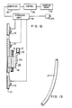
- the sleeve blanks are, in the practice of this invention, slightly curved or bowed.
- a bimetallic sleeve blank 1 meter (40") long is bowed by 2 mm ⁇ 0.5 mm at the longitudinal center or at the point of maximum departure from linearity.
- a sleeve blank 1 meter (40") long of INCONEL 690 alone is typically bowed 1.5 mm ⁇ 0.5 mm at the longitudinal center or at the point of maximum departure from linearity.
- the tubes which are sleeved are linear so that when a bowed sleeve blank is thrust into a tube, the tube exerts a force tending to straighten the sleeve blank.
- the sleeve then exerts a restoring force against the wall of the sleeved tube so that the sleeve is firmly held in the tube and does not fall out when the lift bar is retracted.
- the sleeve blank is initially advanced towards the tube sheet by the lifter at a low speed, typically 25 mm to 75 per second. Once the sleeve blank enters the tube, the speed is substantially increased, typically to 100 mm to 150 mm per second.
- the cartridge sleeve-blank loader may be mounted on a coordinate transport; the loader may be provided with lockpins which are engaged in tubes that are so located near the tube to be sleeved that a sleeve blank in the sleeving position would be centered under the tube to be sleeved.
- the tubes may be regarded as arrayed in rows and columns or lines. Typically, the tubes in the rows may be aligned. Each set directly along a column or the tubes in each row may be staggered with respect to the tubes in the just preceding and/or just succeeding row.
- the lockpins are adjustable so that the center line between the axes of the pins are parallel to the rows where the tubes are not staggered and parallel to the columns where the tubes are staggered.
- the coordinate transport has the facility for affording precise setting of the sleeve-blank loader as its carriage is moved from position to position for successive sleeving of tubes with the sleeves in the turret.
- the turret is loaded with sleeve blanks in an assembly area outside of the radioactive channel head. An operator or attendant then enters the channel head and quickly removes an empty turret whose sleeve blanks have been inserted from a cartridge sleeve-blank loader mounted on the coordinate transport.
- the loaded turret is then handed to the attendant and he quickly installs the loaded turret in the cartridge loader, sets the loader for unloading the loaded turret and leaves the channel head.
- a handle assembly uniquely suitable for quick positioning of a turret in the sleeve-blank loader is provided.
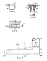
- the apparatus shown in the drawings is a cartridge sleeve-blank loader 21.
- the sleeve-blank loader includes a supporting framework 23, a readily removable and replaceable turret or drum 25 for the sleeve blank 27, a lifter 29 for raising the sleeve blanks 27 and inserting them into cracked or corroded or otherwise damaged tubes 31 in the tube sheet 33 of a steam generator of a nuclear-reactor plant and a drive 35 for the lifter 29 and for indexing the turret 25.
- a part of a sleeve blank 27 is shown in Fig. 1 in the turret in broken lines on the right and a sleeve blank is also shown in broken lines on the lifter 29 which is partly raised.
- the framework 23 includes a front plate 37, side plates 39 and 41 (Fig. 2), a top plate 43 and a rear plate 45.
- the framework 23 is seated on the gearbox assembly 47 of the drive 35.
- the top cover 49 is secured to the back plate 45.
- the front plate 37 and the side plates 39 and 41 of the framework 23 form a cavity which encloses the lifter 29 on three sides.
- the turret 25 extends rearwardly of this part of the framework from the open side to the rear plate 45.
- the sleeve-blank inserting position of the turret 25 is centered outwardly of this opening (Fig. 2).
- Handles 46 Figs.
- Each handle has a V-groove 48 (Fig. 2A) which serves in the ready positioning of a turret 25 in the loader 21.
- the upper pivot 51 for the turret 25 is secured.
- the pivot 51 has a shoulder which seats the inner race 53 of the upper thrust bearing 55 of the turret 25 when the turret is properly positioned in the apparatus.
- the top plate 43 also has an opening 57 (Fig. 3) through which the sleeve blanks 27 are thrust by the lifter 29.
- a roller guide assembly 59 for the sleeve blanks extends over the opening 57.
- the assembly 59 includes oppositely disposed brackets 61 secured to the top plate 43.
- On each bracket a clevis 63 is slidably mounted.
- Each clevis 63 is connected to its bracket 61 by a dowel pin 65 which permits horizontal movement of the clevis.
- a bearing pin 69 is secured by dowel pins 71 to the arms 73 of each clevis 63.
- Grooved rollers 75 are rotatable on the bearings. The sleeve blank 27 as it is passed through opening 57 is firmly engaged and guided by the rollers 75 as they are urged towards each other by the springs 67.
- a hollow-flanged bracket 77 (Fig. 3) extends into an opening in the top plate 43 centrally disposed with respect to the front plate.
- the bracket 77 is secured to the top plate 43.
- Tapered roller bearings 79 (Fig. 1) for the drive screw 81 of the lifter 29 extend into bracket 77.
- the bearings 79 are secured between a shoulder on the screw 81 and a lock washer 83 held by a bearing screw 85 against the rotating race 87 of the upper bearing.
- Lockpin assemblies 89 are suspended from the top plate 43 symmetrically with respect to the center line perpendicular to the front plate 37.
- Each lockpin assembly 89 includes a lockpin 91 (Fig. 5) movable upwardly into a selected tube 31, properly positioned with respect to a tube to be sleeved, and retractable downwardly by a piston not shown in a cylinder 93.
- the hydraulic fluid for moving the piston is supplied through a fitting 95 (Fig. 1).
- the fitting 95 is suspended from an angle bracket 97 connected to the back plate 45.
- the cylinder 93 is suspended from a flanged support 99 screwed into a flanged sleeve 101 secured to top plate 43 by locating pins 103 in the underside of the plate.
- the flanged sleeve 101 is screwed into a ring 105 appropriately positioned in the oval cavity 107 (Fig. 3) in the top plate.
- Two sets of locating holes for the pins 103 are provided. With the pins 103 in one set of holes, the ring 105 is seated in the left-hand end of the cavity with reference to Fig. 3 as shown. With the pins 103 in the other set, the ring 105 is seated in the right-hand end of the cavity 107 with reference to Fig. 3. Again referring to fig.
- the member 99 and the cylinder 93 suspended from it are locked to the sleeve 101 and the top plate 43 by a nut 109 screwed onto the member 99 and firmly engaging the flange of the sleeve 101.
- the holes 110 serve for engagement by a wrench to disconnect the lockpin assembly 89 from the plate 43.
- the turret 25 (Fig. 1) includes a cylinder 111. Flanged end caps 113 and 115 are secured to the upper and lower ends of cylinder 111 by a plurality of uniformly spaced spring pins 117.
- the upper end cap has a central shouldered extension 119 in whose shoulder the upper thrust bearing 55 is secured.
- the lower end cap 115 has a shouldered opening in whose shoulder the lower thrust bearing 121 is secured.
- the plate 127 has a spherical groove which is engaged by a ball (not shown) in a spring-activated plunger 129 extending from a sleeve 131 secured in the torque arm 133 of the indexing drive-shaft assembly 135.
- the turret 25 is indexed by the plunger 129 when the torque arm 133 is rotated.
- Upper and lower index plates or rings 137 and 139 are bolted to the flanges 141 and 143 of the end caps 113 and 115. The bottoms of the index plates are flush with the bottoms of the flanges.
- a plurality of holes 145 defined by circularly cylindrical arcs are provided in the upper index plate 137.
- Cavities 147 defined by circularly cylindrical arcs are provided in the lower index plate 139.
- the cavities 147 in the lower index plate 139 face upwardly.
- the holes 145 and cavities 147 at each angular position of the turret are coaxial and serve as a receptacle for a sleeve blank 27.
- Each cavity 147 engages the lower end of a sleeve blank.
- Slots 149 (Fig. 2) extend through each cavity 147.
- Slots 150 also extend through each hole 145.
- the slots are penetrable by the lifting arm 151 of the lifter 29.
- the lifting arm 151 has a projection 153 which engages the lower end of a sleeve blank 27 in a receptacle 145-147.
- each sleeve blank is flared.
- the index plates 137 and 139 have holes 155 around their periphery for engagement by the handle assembly 341 (Fig. 14, 15, 16) for handling the turret during installation.
- the lifter 29 includes, in addition to the drive screw 81, the bearings 79, the bearing nut 83, and the lifter arm 151, a saddle block or carriage 161 (Figs. 1, 2).
- the saddle block 161 is hollow and within the saddle block a ball nut 163 is secured to a block 165 connected to the carriage.
- the lifter arm 151 is supported from the surface of the saddle block which faces the turret 25.
- the lifter arm 151 is of generally L-shaped longitudinal cross section with the projection 153 on its horizontal surface.
- the saddle block 161 is guided by shafts, bars or rails 167.
- the shafts 167 extend between the upper plate 49 of the gearbox 47 and the top plate 43 of the gear box 47.
- the shafts 167 are supported by rail supports 169 mounted on the front wall 37 of the framework 23.
- the saddle block 161 carries ball bushings 171 (Figs. 2, 6) which engage and move along the shafts when the saddle block moves upwardly or downwardly.
- Each bushing 171 is provided with a seal 173 at each end.
- the bushings 171 have slots so that they clear the rail supports 169 as the bushings move upwardly or downwardly with the saddle block 161.
- Limit switches 175, 177 and 179 mounted inwardly along the front plate 37 are actuable by the saddle block 161.
- limit switch 175 When the saddle block is in the lowermost position, it actuates limit switch 175 to indicate that it is in this position. When the saddle block is in the uppermost position, it actuates limit switch 179. When the saddle block is in a position such that the sleeve blank 27 has just entered the tube 31 to be sleeved, it actuates limit switch 177.
- limit switches 175, 177, 179 are microswitches which are closed by engagement with the saddle block 161 and reopen automatically when disengaged.
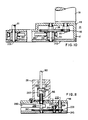
- the limit switches 175, 177, 179 are connected to a signalling unit 181 (Fig. 12) which transmits intelligence as to the position of the saddle block 161 and sleeve blank 27 which it carries to a computer 183.
- the computer 183 sets the insertion drive 187 to operate in dependence upon the position of the saddle block.
- the insertion speed is low so that the sleeve blank 27 is advanced at a low speed.
- limit switch 177 is actuated, indicating entry of the sleeve blank into tube 31, the speed of the insertion drive 187 is increased substantially increasing the speed of insertion.
- the limit switch 179 is actuated, the insertion drive is stopped and after a short delay, reversed.
- switch 177 is actuated on the retraction stroke, the speed of the insertion drive 187 is reduced.
- the drive 35 includes, in addition to the indexing shaft assembly 135, the torque arm 133 and the sleeve 131 and plunger 129, a sleeve-blank insertion motor 191 and an indexing motor 193 (Figs. 1, 2, 7-11).
- the motors 191 and 193 are mounted on the top cover 49 of the gearbox 47.
- the sleeve-blank insertion motor 191 drives a pinion 195 through its shaft 197.
- the pinion 195 meshes with a speed reducing gear 199 on whose shaft 201 a sprocket sheel 203 is mounted.
- a timing belt 205 driven by sprocket wheel 203, drives the drive screw 81 through a sprocket wheel 207 keyed to the shaft 209 of drive screw 81.
- the speed of the motor 191 is varied by varying the voltage impressed on this motor.
- the sleeve blank is advanced at a velocity of 50 mm (2") per second and with 40 volts on the motor 191, the sleeve blank is advanced at 90 mm (3.6") per second.
- a shaft 211 is driven by the indexing motor 193 through a multi-jaw coupling 211.
- the shaft 213 drives a pinion 215 and a cam 217.
- the cam has a flat surface over about 135° of its circumference (FIg. 8) and a cylindrical surface over the remainder of its circumference.
- the cam is engaged by a cam follower 219 on the switch arm 221 of a limit switch 223 suspended from the bottom of top plate 49 of the gearbox 47.
- the cam follower 219 engages the flat surface, the arm 221 is moved counterclockwise closing the switch.
- the cam follower is in the cylindrical part of the cam surface, the arm 221 is pivoted clockwise and the switch is open.
- the pinion 215 meshes with an idler gear 225.
- the idler gear 225 drives a gear 227 at the same speed of rotation as the pinion 215.
- the cam 229 of the Geneva movement 231 is on the shaft 226 of gear 227.
- the cam 229 carries a pin 231 which, as the cam rotates, engages successively in the slots 233 of the star gear 235 of the Generva movement indexing the star gear.
- the idler gear 241 is supported on a bracket 243 secured to the base 245 of the gearbox.
- the idler gear 241 meshes with a speed-reducing gear 247 which drives a shaft 249.
- the shaft 249 drives the indexing shaft assembly 135.
- the train of gears 215, 225, 227, 235, 241 and 247 are such that the shaft 249 is indexed one step for each complete rotation of gear 215 and cam 217.
- Limit switch 223 is actuated once for each indexing step of the shaft 249 and the turret 25. Actuation of the switch 223 transmits intelligence to computer 183 that an indexing operation has been completed.
- the shaft 249 is centered under the insertion position of the turret 25.
- the index shaft assembly 135 (Figs. 1, 11) includes a circularly cylindrical flanged housing 291.
- the housing is seated on the top plate 49 of the gearbox 47 with its heel-like projection engaging a circular shoulder in the surface of top 49.
- the shaft 249 passes through a bearing 293 in the top 49 and terminates in a splined extension 295 which extends into the housing 291.
- the extension 295 is engaged by a splined bushing 297.
- the splined bushing 297 is connected by a pin 299 to the splined extension 301 of a shaft 303.
- the lower pivot 125 is secured to the top of shaft 303 by a central screw 305.
- the torque arm 133 is split at the end remote from the sleeve 131 and is clamped to the top of shaft 303 by screw 307.
- the assembly 135 also includes a piston 309.
- the shaft 303 extends through bushings 297 in a central opening in the piston 309.
- the upper surfaces of the bushing 297 and of the splined section 301 are flush and they abut a spacer 313 abutting the inner surface of the flange 315 of the piston 309.
- the piston 309 is urged upwardly by a spring 323 which is compressed between a shouldered annulus 325 supported on a ring 327 secured near the bottom of the inner wall of housing 291 and the bottom surface of the piston 309.
- the upper turn of the spring 323 is seated in the annular space between an annular tip of the piston and the outer surface of the splined bushing 297.
- the piston 309 maintains the parts connected to it, including the shaft 303 and its splined section 301, the bushing 297, the torque arm 133, the plunger 129 and the lower pivot 125 in the uppermost position.
- the pivot 125 is urged into firm locked engagement with thrust bearing 121 securing the turret 25 in its operating position.
- the upward force of the spring 323 is counteracted by compressed air supplied through fitting 327, conductor 329 and nozzle 331 to the top of the flange 315 of the piston. Fitting 327 is supported on angle bracket 97.
- the force of spring 323 is counteracted and the piston 309 and the parts connected to it are moved downwardly disconnecting lower pivot 125 from thrust bearing 121 so that the turret 25 may be readily removed.
- the piston 309 and the parts connected to it snap upwardly and the pivot 125 is snapped into firm engagement with the thrust bearing 121 of a turret 25 which is positioned for operation.
- the indexing shaft indexes the turret through splined bushing 297, splined section 301, torque arm 133, plunger 129 and plate 127.
- the handle assembly 341 (Fig. 14, 15, 16) is attached to a turret 25 loaded with sleeve blanks 27. As so loaded, it is handed to the attendant in the channel head of the steam generator to be sleeved. The attendant uses the handle assembly 341 to position the turret 25 in the cartridge sleeve-blank loader 21. Once the turret is properly positioned, it is locked and the handle assembly is removed.
- the handle assembly 341 includes a supporting plate 343.
- a handle 345 is secured longitudinally of the plate 343 in a position where the handle may be readily grasped to manipulate the turret 25.
- a yoke 347 is secured to plate 343.
- the inner surface 349 (Fig. 16) of the yoke 347 has the contour of an arc of a circle having a slightly greater radius than the periphery of the upper index plates 145 so that it seats snugly against this plate.
- a top key 348 extends from the yoke 347.
- a slide assembly 351 is bolted to the inclined sides of the yoke 347.
- the slide assembly 351 includes two end slides 353 and 355 connected by a tie plate 357. Each of the slides 353 and 355 has a pin 359 extending from a projection 360 at its outer end.
- the pins 359 are sometimes referred to and may be described as plungers.
- the bolts 361 and 363 which join the slide assembly 351 to the yoke 347 pass through slots 365 (Fig. 15) in the slides so that the slide assembly is slidable relative to the yoke 347.
- the slide assembly 351 is slid longitudinally of plate 343 by operation of a mechanism 366 including a handle 367.
- the handle 367 is sometimes referred to as a plunger clamp since it clamps the plungers 359 in advanced and retracted positions.
- Handle 367 operates through a linkage mounted on bracket 369 secured to plate 343.
- a pair of parallel plates 371 extending from the inner end of handle 367 are pivotal about a pin 373 secured between parallel arms 375 of bracket 369.
- a lever 377 is pivotal near one end on a pin 379 extending between plates 371. Near the other end this lever 377 is pivotal on a pin 381 secured to the bifurcated end 382 of a shaft 383.
- the shaft is slidable in a bearing 385 extending from bracket 369.
- the shaft 383 carries a retainer 387 for a spring 387.
- the spring 389 is compressible by the shaft 383 between the retainer 387 and a retainer 391 which is secured to a spring support 393 connected to tie plate 357.
- the shaft 383 passes through the retainer 391, the spring support 393 and through a second spring 395.
- the second spring 395 extends between retainer 397, secured to the spring support 393 on the face opposite to the retainer 391, and retainer 399.
- the springs 389 and 395 are so-related that the shaft 383 passes through dead center in its advanced or retracted positions.
- the shaft 383 and the slide assembly 351 connected to it are locked in their extreme positions by a pin 401 connected to a cable 403 extending from bracket 369.
- support plate 343 carries a block 405 having projections 407 from which pins 409 extend.
- a key 411 extends from the end of block 405. Displaced from the end of the key 411, there is a V-projection 413 shaped to seat in the V-groove 48 of one of the handles 46.
- the block 405 is shaped, similarly to the yoke 347, so that it seats against the periphery of the lower index plate 147.
- the handle assembly is connected to a turret 25 carrying sleeve blanks 27 in its receptacles.
- the circular arcuate surface (not shown) of the block 405 is seated against the coaxial circular surface of the lower index plate 139 and the pins 409 are inserted in holes 155 along the periphery of the index plate 139.
- the two pins 409 are inserted in the two end holes of a sequence of four holes.
- the handle 367 is locked in the most counterclockwise position, with reference to Fig. 15.
- the handle assembly 341 is swung to the position in which the surface 349 is seated in the circular rim of the upper index plate 137 with the pins or plungers 359 aligned with the first and the fourth holes 155 of a sequence of four holes.
- the shaft 383 is now unlocked by removal of the pin 401 from the bearing 385 and the handle 367 is turned in a clockwise direction injecting the pins or plungers 359 in the two holes 155 of the index plate at the ends of a sequence of four.
- the pin 401 is inserted in bearing 385 to lock the handle assembly 341 in the position in which it is mounted on the sleeve-blank loaded turret 25.
- the loading of turret 25 and the mounting of the handle assembly takes place outside of the channel head of the steam generator.
- the attendant now enters the channel head.
- the valve 415 (Fig. 1) in the open position, the attendant applies compressed air to piston 315.
- the piston 315 and the shaft 303, the torque arm 133 and the lower pivot 125 are retracted.
- the unloaded turret 25 is readily removable and is removed by the attendant and given to personnel outside of the channel head.
- the valve 415 is left in the open setting.
- the personnel outside of the channel head now give the loaded turret to the attendant.
- Grasping the handle 345 the attendant inserts to top key in a slot 417 (Fig. 14) in the top plate of the sleeve-blank loader 21, engages the bottom key 411 with the side of the handle 46 (Fig.
Landscapes
- Engineering & Computer Science (AREA)
- Mechanical Engineering (AREA)
- Physics & Mathematics (AREA)
- Thermal Sciences (AREA)
- General Engineering & Computer Science (AREA)
- High Energy & Nuclear Physics (AREA)
- Monitoring And Testing Of Nuclear Reactors (AREA)
- Automatic Assembly (AREA)
Applications Claiming Priority (2)
| Application Number | Priority Date | Filing Date | Title |
|---|---|---|---|
| US06/580,038 US4653164A (en) | 1984-02-14 | 1984-02-14 | Sleeving of tubes of steam generator in hostile environment |
| US580038 | 1984-02-14 |
Related Parent Applications (1)
| Application Number | Title | Priority Date | Filing Date |
|---|---|---|---|
| EP85100570.2 Division | 1985-01-21 |
Publications (3)
| Publication Number | Publication Date |
|---|---|
| EP0299539A2 EP0299539A2 (en) | 1989-01-18 |
| EP0299539A3 EP0299539A3 (en) | 1989-09-27 |
| EP0299539B1 true EP0299539B1 (en) | 1992-07-29 |
Family
ID=24319403
Family Applications (2)
| Application Number | Title | Priority Date | Filing Date |
|---|---|---|---|
| EP88111679A Expired - Lifetime EP0299539B1 (en) | 1984-02-14 | 1985-01-21 | Apparatus for sleeving damaged tubes of a nuclear steam generator |
| EP85100570A Expired EP0152778B1 (en) | 1984-02-14 | 1985-01-21 | Sleeving of tubes of steam generator in hostile environment |
Family Applications After (1)
| Application Number | Title | Priority Date | Filing Date |
|---|---|---|---|
| EP85100570A Expired EP0152778B1 (en) | 1984-02-14 | 1985-01-21 | Sleeving of tubes of steam generator in hostile environment |
Country Status (8)
| Country | Link |
|---|---|
| US (1) | US4653164A (zh) |
| EP (2) | EP0299539B1 (zh) |
| JP (1) | JPS60191101A (zh) |
| KR (1) | KR930006785B1 (zh) |
| CA (1) | CA1240625A (zh) |
| DE (2) | DE3570848D1 (zh) |
| ES (1) | ES8703210A1 (zh) |
| ZA (1) | ZA85588B (zh) |
Families Citing this family (12)
| Publication number | Priority date | Publication date | Assignee | Title |
|---|---|---|---|---|
| FR2598202B1 (fr) * | 1986-04-30 | 1990-02-09 | Framatome Sa | Procede de chemisage d'un tube peripherique d'un generateur de vapeur. |
| FR2598209B1 (fr) * | 1986-04-30 | 1988-08-12 | Framatome Sa | Procede et dispositif de chemisage a distance d'un tube de generateur de vapeur d'un reacteur nucleaire a eau sous pression. |
| US4829648A (en) * | 1987-01-27 | 1989-05-16 | Westinghouse Electric Corp. | Apparatus and method for simultaneously loading a reinforcing sleeve and mandrel into a tube |
| DE8712772U1 (de) * | 1987-09-22 | 1989-01-19 | Siemens AG, 1000 Berlin und 8000 München | Gerät zur Inspektion und/oder Reparatur von Wärmetauscherrohren |
| US4873753A (en) * | 1988-02-01 | 1989-10-17 | Combustion Engineering, Inc. | Control system for a rotation station for remotely installing a mechanical tube plug |
| FR2630365B1 (fr) * | 1988-04-25 | 1990-07-13 | Stein Industrie | Machine de chemisage interne a distance par manchon de l'extremite de tubes d'echangeurs de chaleur |
| US5029388A (en) * | 1988-12-08 | 1991-07-09 | Westinghouse Electric Corp. | Apparatus and process for sleeving the heat exchanger tubes of nuclear steam generators |
| US5367768A (en) * | 1992-12-17 | 1994-11-29 | Mpr Associates, Inc. | Methods of repairing inconel 600 nozzles of pressurized water reactor vessels |
| CN102152096B (zh) * | 2011-03-28 | 2013-05-29 | 龚雅萍 | 螺丝刀自动装配机 |
| CN109048256B (zh) * | 2018-09-07 | 2024-03-12 | 苏州梯图智能设备科技有限公司 | 一种产品自动精准插装机构 |
| CN109967993A (zh) * | 2019-01-14 | 2019-07-05 | 飞马智科信息技术股份有限公司 | 彩涂板生产线用纸套筒自动安装装置及纸套筒自动安装方法 |
| CN114392867B (zh) * | 2021-12-23 | 2023-09-08 | 陕西法士特齿轮有限责任公司 | 一种变速箱后轴承盖油封压装涂脂设备及方法 |
Citations (1)
| Publication number | Priority date | Publication date | Assignee | Title |
|---|---|---|---|---|
| US4329769A (en) * | 1979-12-05 | 1982-05-18 | Westinghouse Electric Corp. | Apparatus for working on tubesheets |
Family Cites Families (9)
| Publication number | Priority date | Publication date | Assignee | Title |
|---|---|---|---|---|
| GB757617A (en) * | 1953-11-11 | 1956-09-19 | Frederick Bramston Austin | A new or improved screwdriver attachment unit for feeding screws to a screwdriver |
| US2884662A (en) * | 1954-07-19 | 1959-05-05 | Clarence V Mcguire | Mold and process of making the same |
| US3250420A (en) * | 1964-02-27 | 1966-05-10 | Vehoc Corp | Internal access means for containers |
| US4069573A (en) * | 1976-03-26 | 1978-01-24 | Combustion Engineering, Inc. | Method of securing a sleeve within a tube |
| US4173060A (en) * | 1977-06-24 | 1979-11-06 | Westinghouse Electric Corp. | System and method for retubing a steam generator |
| US4368571A (en) * | 1980-09-09 | 1983-01-18 | Westinghouse Electric Corp. | Sleeving method |
| US4406856A (en) * | 1980-09-29 | 1983-09-27 | Westinghouse Electric Corp. | Removal of portions of tubes from steam generator of nuclear reactor |
| FR2529109B1 (fr) * | 1982-06-28 | 1990-02-23 | Westinghouse Electric Corp | Procede et appareil d'insertion a distance de manchons dans les tubes d'echangeurs de chaleur |
| US4483061A (en) * | 1982-09-28 | 1984-11-20 | Apx Group, Inc. | Double walled tubing and process for producing same |
-
1984
- 1984-02-14 US US06/580,038 patent/US4653164A/en not_active Expired - Fee Related
-
1985
- 1985-01-21 DE DE8585100570T patent/DE3570848D1/de not_active Expired
- 1985-01-21 DE DE8888111679T patent/DE3586426D1/de not_active Expired - Lifetime
- 1985-01-21 EP EP88111679A patent/EP0299539B1/en not_active Expired - Lifetime
- 1985-01-21 EP EP85100570A patent/EP0152778B1/en not_active Expired
- 1985-01-23 CA CA000472671A patent/CA1240625A/en not_active Expired
- 1985-01-24 ZA ZA85588A patent/ZA85588B/xx unknown
- 1985-02-13 ES ES540384A patent/ES8703210A1/es not_active Expired
- 1985-02-14 JP JP60025343A patent/JPS60191101A/ja active Granted
- 1985-02-14 KR KR1019850000956A patent/KR930006785B1/ko not_active Expired - Lifetime
Patent Citations (1)
| Publication number | Priority date | Publication date | Assignee | Title |
|---|---|---|---|---|
| US4329769A (en) * | 1979-12-05 | 1982-05-18 | Westinghouse Electric Corp. | Apparatus for working on tubesheets |
Also Published As
| Publication number | Publication date |
|---|---|
| ZA85588B (en) | 1986-04-30 |
| EP0152778A2 (en) | 1985-08-28 |
| KR850006768A (ko) | 1985-10-16 |
| ES540384A0 (es) | 1987-02-01 |
| EP0152778A3 (en) | 1986-08-27 |
| JPH0354241B2 (zh) | 1991-08-19 |
| DE3570848D1 (en) | 1989-07-13 |
| KR930006785B1 (ko) | 1993-07-23 |
| EP0299539A2 (en) | 1989-01-18 |
| ES8703210A1 (es) | 1987-02-01 |
| EP0299539A3 (en) | 1989-09-27 |
| JPS60191101A (ja) | 1985-09-28 |
| CA1240625A (en) | 1988-08-16 |
| DE3586426D1 (de) | 1992-09-03 |
| US4653164A (en) | 1987-03-31 |
| EP0152778B1 (en) | 1989-06-07 |
Similar Documents
| Publication | Publication Date | Title |
|---|---|---|
| EP0299539B1 (en) | Apparatus for sleeving damaged tubes of a nuclear steam generator | |
| EP0037135B1 (en) | Pallet transfer system | |
| EP0040501B1 (en) | Automatic tool changer and tool storage arrangement for machine tool | |
| US4545569A (en) | Apparatus for positioning, connecting and handling components | |
| US4724607A (en) | Apparatus for rebuilding nuclear fuel assemblies | |
| EP0178944A1 (en) | Industrial robots | |
| US4155237A (en) | Machine for splining thin-walled power transmission members | |
| US4599786A (en) | Grinding machine with apparatus for changing grinding wheel tools and workpieces | |
| US5197320A (en) | Method of and apparatus for bending a metal tube of a small diameter | |
| EP0140586A2 (en) | Sleeving of tubes in hostile environments | |
| EP0011710B1 (en) | Machine tool with an automatic tool changer for single tools and multiple spindle toolheads, and a multiple spindle toolhead | |
| EP1725501B1 (de) | Glasbearbeitungsmaschine | |
| DE2811357A1 (de) | Einrichtung zum automatischen werkzeugwechsel an mehrspindelbohrmaschinen | |
| EP0126447B1 (en) | Chuck jaw changer for a machine tool | |
| JPS60145288A (ja) | フランジ及びパイプの組立装置 | |
| US6286394B1 (en) | Arrangement for changing the nut holding a roll ring | |
| US5133925A (en) | Device for centering a servicing tool in a steam generator tube | |
| US3531969A (en) | Method and apparatus for replacing work roll chocks | |
| JPH0581380B2 (zh) | ||
| RU2060141C1 (ru) | Металлорежущий станок | |
| SU975305A1 (ru) | Многопозиционное зажимное устройство | |
| EP0594381A1 (en) | Control blade servicing assembly | |
| CN1129840A (zh) | 核电站反应堆测温热电偶插装机械手 | |
| KR820001351B1 (ko) | 공작기계의 다축 공구헤드 | |
| JPH0613769Y2 (ja) | マシニングセンター |
Legal Events
| Date | Code | Title | Description |
|---|---|---|---|
| PUAI | Public reference made under article 153(3) epc to a published international application that has entered the european phase |
Free format text: ORIGINAL CODE: 0009012 |
|
| AC | Divisional application: reference to earlier application |
Ref document number: 152778 Country of ref document: EP |
|
| AK | Designated contracting states |
Kind code of ref document: A2 Designated state(s): BE CH DE FR GB IT LI SE |
|
| PUAL | Search report despatched |
Free format text: ORIGINAL CODE: 0009013 |
|
| AK | Designated contracting states |
Kind code of ref document: A3 Designated state(s): BE CH DE FR GB IT LI SE |
|
| 17P | Request for examination filed |
Effective date: 19900216 |
|
| 17Q | First examination report despatched |
Effective date: 19910621 |
|
| GRAA | (expected) grant |
Free format text: ORIGINAL CODE: 0009210 |
|
| AC | Divisional application: reference to earlier application |
Ref document number: 152778 Country of ref document: EP |
|
| AK | Designated contracting states |
Kind code of ref document: B1 Designated state(s): BE CH DE FR GB IT LI SE |
|
| PG25 | Lapsed in a contracting state [announced via postgrant information from national office to epo] |
Ref country code: IT Free format text: LAPSE BECAUSE OF FAILURE TO SUBMIT A TRANSLATION OF THE DESCRIPTION OR TO PAY THE FEE WITHIN THE PRESCRIBED TIME-LIMIT;WARNING: LAPSES OF ITALIAN PATENTS WITH EFFECTIVE DATE BEFORE 2007 MAY HAVE OCCURRED AT ANY TIME BEFORE 2007. THE CORRECT EFFECTIVE DATE MAY BE DIFFERENT FROM THE ONE RECORDED. Effective date: 19920729 Ref country code: DE Effective date: 19920729 |
|
| ET | Fr: translation filed | ||
| REF | Corresponds to: |
Ref document number: 3586426 Country of ref document: DE Date of ref document: 19920903 |
|
| PG25 | Lapsed in a contracting state [announced via postgrant information from national office to epo] |
Ref country code: GB Effective date: 19930121 |
|
| PG25 | Lapsed in a contracting state [announced via postgrant information from national office to epo] |
Ref country code: SE Effective date: 19930122 |
|
| PG25 | Lapsed in a contracting state [announced via postgrant information from national office to epo] |
Ref country code: BE Effective date: 19930131 Ref country code: LI Effective date: 19930131 Ref country code: CH Effective date: 19930131 |
|
| PLBE | No opposition filed within time limit |
Free format text: ORIGINAL CODE: 0009261 |
|
| STAA | Information on the status of an ep patent application or granted ep patent |
Free format text: STATUS: NO OPPOSITION FILED WITHIN TIME LIMIT |
|
| 26N | No opposition filed | ||
| BERE | Be: lapsed |
Owner name: WESTINGHOUSE ELECTRIC CORP. Effective date: 19930131 |
|
| GBPC | Gb: european patent ceased through non-payment of renewal fee |
Effective date: 19930121 |
|
| REG | Reference to a national code |
Ref country code: CH Ref legal event code: PL |
|
| PGFP | Annual fee paid to national office [announced via postgrant information from national office to epo] |
Ref country code: FR Payment date: 19931231 Year of fee payment: 10 |
|
| EUG | Se: european patent has lapsed |
Ref document number: 88111679.2 Effective date: 19930810 |
|
| PG25 | Lapsed in a contracting state [announced via postgrant information from national office to epo] |
Ref country code: FR Effective date: 19950929 |
|
| REG | Reference to a national code |
Ref country code: FR Ref legal event code: ST |