EP0140586A2 - Sleeving of tubes in hostile environments - Google Patents
Sleeving of tubes in hostile environments Download PDFInfo
- Publication number
- EP0140586A2 EP0140586A2 EP84306624A EP84306624A EP0140586A2 EP 0140586 A2 EP0140586 A2 EP 0140586A2 EP 84306624 A EP84306624 A EP 84306624A EP 84306624 A EP84306624 A EP 84306624A EP 0140586 A2 EP0140586 A2 EP 0140586A2
- Authority
- EP
- European Patent Office
- Prior art keywords
- mandrel
- tube
- sleeve
- rolling
- rolls
- Prior art date
- Legal status (The legal status is an assumption and is not a legal conclusion. Google has not performed a legal analysis and makes no representation as to the accuracy of the status listed.)
- Ceased
Links
Images


Classifications
-
- F—MECHANICAL ENGINEERING; LIGHTING; HEATING; WEAPONS; BLASTING
- F02—COMBUSTION ENGINES; HOT-GAS OR COMBUSTION-PRODUCT ENGINE PLANTS
- F02G—HOT GAS OR COMBUSTION-PRODUCT POSITIVE-DISPLACEMENT ENGINE PLANTS; USE OF WASTE HEAT OF COMBUSTION ENGINES; NOT OTHERWISE PROVIDED FOR
- F02G1/00—Hot gas positive-displacement engine plants
- F02G1/04—Hot gas positive-displacement engine plants of closed-cycle type
- F02G1/043—Hot gas positive-displacement engine plants of closed-cycle type the engine being operated by expansion and contraction of a mass of working gas which is heated and cooled in one of a plurality of constantly communicating expansible chambers, e.g. Stirling cycle type engines
-
- B—PERFORMING OPERATIONS; TRANSPORTING
- B21—MECHANICAL METAL-WORKING WITHOUT ESSENTIALLY REMOVING MATERIAL; PUNCHING METAL
- B21D—WORKING OR PROCESSING OF SHEET METAL OR METAL TUBES, RODS OR PROFILES WITHOUT ESSENTIALLY REMOVING MATERIAL; PUNCHING METAL
- B21D39/00—Application of procedures in order to connect objects or parts, e.g. coating with sheet metal otherwise than by plating; Tube expanders
- B21D39/04—Application of procedures in order to connect objects or parts, e.g. coating with sheet metal otherwise than by plating; Tube expanders of tubes with tubes; of tubes with rods
-
- B—PERFORMING OPERATIONS; TRANSPORTING
- B23—MACHINE TOOLS; METAL-WORKING NOT OTHERWISE PROVIDED FOR
- B23P—METAL-WORKING NOT OTHERWISE PROVIDED FOR; COMBINED OPERATIONS; UNIVERSAL MACHINE TOOLS
- B23P19/00—Machines for simply fitting together or separating metal parts or objects, or metal and non-metal parts, whether or not involving some deformation; Tools or devices therefor so far as not provided for in other classes
- B23P19/02—Machines for simply fitting together or separating metal parts or objects, or metal and non-metal parts, whether or not involving some deformation; Tools or devices therefor so far as not provided for in other classes for connecting objects by press fit or for detaching same
- B23P19/022—Extracting or inserting relatively long parts
-
- F—MECHANICAL ENGINEERING; LIGHTING; HEATING; WEAPONS; BLASTING
- F28—HEAT EXCHANGE IN GENERAL
- F28F—DETAILS OF HEAT-EXCHANGE AND HEAT-TRANSFER APPARATUS, OF GENERAL APPLICATION
- F28F19/00—Preventing the formation of deposits or corrosion, e.g. by using filters or scrapers
- F28F19/002—Preventing the formation of deposits or corrosion, e.g. by using filters or scrapers by using inserts or attachments
-
- F—MECHANICAL ENGINEERING; LIGHTING; HEATING; WEAPONS; BLASTING
- F02—COMBUSTION ENGINES; HOT-GAS OR COMBUSTION-PRODUCT ENGINE PLANTS
- F02G—HOT GAS OR COMBUSTION-PRODUCT POSITIVE-DISPLACEMENT ENGINE PLANTS; USE OF WASTE HEAT OF COMBUSTION ENGINES; NOT OTHERWISE PROVIDED FOR
- F02G2243/00—Stirling type engines having closed regenerative thermodynamic cycles with flow controlled by volume changes
- F02G2243/30—Stirling type engines having closed regenerative thermodynamic cycles with flow controlled by volume changes having their pistons and displacers each in separate cylinders
- F02G2243/50—Stirling type engines having closed regenerative thermodynamic cycles with flow controlled by volume changes having their pistons and displacers each in separate cylinders having resonance tubes
- F02G2243/52—Stirling type engines having closed regenerative thermodynamic cycles with flow controlled by volume changes having their pistons and displacers each in separate cylinders having resonance tubes acoustic
-
- F—MECHANICAL ENGINEERING; LIGHTING; HEATING; WEAPONS; BLASTING
- F02—COMBUSTION ENGINES; HOT-GAS OR COMBUSTION-PRODUCT ENGINE PLANTS
- F02G—HOT GAS OR COMBUSTION-PRODUCT POSITIVE-DISPLACEMENT ENGINE PLANTS; USE OF WASTE HEAT OF COMBUSTION ENGINES; NOT OTHERWISE PROVIDED FOR
- F02G2244/00—Machines having two pistons
- F02G2244/50—Double acting piston machines
-
- Y—GENERAL TAGGING OF NEW TECHNOLOGICAL DEVELOPMENTS; GENERAL TAGGING OF CROSS-SECTIONAL TECHNOLOGIES SPANNING OVER SEVERAL SECTIONS OF THE IPC; TECHNICAL SUBJECTS COVERED BY FORMER USPC CROSS-REFERENCE ART COLLECTIONS [XRACs] AND DIGESTS
- Y10—TECHNICAL SUBJECTS COVERED BY FORMER USPC
- Y10T—TECHNICAL SUBJECTS COVERED BY FORMER US CLASSIFICATION
- Y10T29/00—Metal working
- Y10T29/53—Means to assemble or disassemble
- Y10T29/53039—Means to assemble or disassemble with control means energized in response to activator stimulated by condition sensor
- Y10T29/53061—Responsive to work or work-related machine element
- Y10T29/53065—Responsive to work or work-related machine element with means to fasten by deformation
-
- Y—GENERAL TAGGING OF NEW TECHNOLOGICAL DEVELOPMENTS; GENERAL TAGGING OF CROSS-SECTIONAL TECHNOLOGIES SPANNING OVER SEVERAL SECTIONS OF THE IPC; TECHNICAL SUBJECTS COVERED BY FORMER USPC CROSS-REFERENCE ART COLLECTIONS [XRACs] AND DIGESTS
- Y10—TECHNICAL SUBJECTS COVERED BY FORMER USPC
- Y10T—TECHNICAL SUBJECTS COVERED BY FORMER US CLASSIFICATION
- Y10T29/00—Metal working
- Y10T29/53—Means to assemble or disassemble
- Y10T29/531—Nuclear device
-
- Y—GENERAL TAGGING OF NEW TECHNOLOGICAL DEVELOPMENTS; GENERAL TAGGING OF CROSS-SECTIONAL TECHNOLOGIES SPANNING OVER SEVERAL SECTIONS OF THE IPC; TECHNICAL SUBJECTS COVERED BY FORMER USPC CROSS-REFERENCE ART COLLECTIONS [XRACs] AND DIGESTS
- Y10—TECHNICAL SUBJECTS COVERED BY FORMER USPC
- Y10T—TECHNICAL SUBJECTS COVERED BY FORMER US CLASSIFICATION
- Y10T29/00—Metal working
- Y10T29/53—Means to assemble or disassemble
- Y10T29/53113—Heat exchanger
- Y10T29/53122—Heat exchanger including deforming means
Definitions
- This invention relates to the art of sleeving of tubes, e.g., fluid carrying conductors. It has particular relationship to the sleeving of corroded or damaged coolant-carrying conductors; i.e. the primary conductors, of the steam generator of a nuclear reactor plant.
- sleeves are inserted into the tubular conductors.
- the sleeves may be of different lengths, typically 686 mm, 762 mm, 912 mm or 1115 mm (27, 30, 36 or 44 inches).
- the lower end of each sleeve is coincident with the lower end of the coolant conductor in which it is inserted.
- a sleeve, once inserted, is expanded typically near its upper end and near its lower end in a region within the tube sheet. After being expanded the sleeve is rolled in the top and bottom regions so that a mechanical joint is formed between the sleeve and the tubular conductor.
- a sleeve is rolled over a length of about (2-1/8") 55 mm at the lower end and (1-1/2") 38.5 mm at the upper end.
- Each joint formed by the rolling should be capable of effectively resisting the penetration of the high pressure coolant, which will flow through the sleeve and through the coolant conductor beyond the sleeve, between the outer surface of the sleeve and the inner surface of the corroded or damaged coolant conductor.
- This invention concerns itself with the rolling of the top and bottom of the sleeve; i.e., the upper end of the sleeve and the part of the sleeve in the tube sheet.
- Access to the coolant conductor for rolling of the sleeve is rather limited and is available through the channel head of the steam generator.
- the environment within the channel head is radioactive so that the time within which personnel may work therein is limited, typically 15 to 45 minutes. After an exposure within a channel head, exposed personnel are not allowed to enter a radioactive environment for several months. Apparatus which is used within a radioactive channel head also becomes radioactively contaminated.
- the channel head is composed of metal and, use of apparatus which requires electrical voltages exceeding about 30 volts within the channel head is prohibited to avoid hazards of electrical shocks to personnel.
- the rolling was carried out with a hand tool.
- This tool included a tube having extendable rolls, sometimes referred to herein, as roller means, in a region thereof.
- a tapered mandrel was provided within the tube.
- the tapered mandrel could be moved by hand axially into the tube to press the rolls into rolling engagement with the sleeve.
- the mandrel was rotatable by an air motor. As the operator started pressing the mandrel into the tube he started the motor so that the mandrel rotated, rotating the rolls while the mandrel was entering the tube. After the rolling was completed the tube and mandrel were removed from the sleeve.
- the invention in its broad form comprises apparatus for rolling to expand a selected region of a sleeve inserted in a tubular coolant conductor of a steam generator of a nuclear-reactor plant, said apparatus including a tube having therein transversely extensible and retractable roller means; moving means connected to said tube, for moving said tube in and out of said sleeve; a mandrel; first means connected to said mandrel, for advancing said mandrel relative to said tube into, and retracting said mandrel from, said tube, said advancing-and-retracting means being set in a standby condition of said apparatus with said mandrel retracted from said tube; means connected to said advancing-and-retracting means and responsive to the positioning of said tube, by inward movement of said moving means, with said roller means at the level of said selected region of said sleeve, for advancing said mandrel into said tube, said mandrel being dimensioned to extend said roller means into engagement with said sleeve
- rolling apparatus including a tube having rolls in a predetermined region thereof.
- the expression "coolant conductors" to designate the primary tubes of a steam generator is used in this application to distinguish these conductors from the tubes which carry the rolls for rolling the sleeves.
- the tube is movable by a remotely actuable drive into the sleeve with its rolls at the level of the region to be rolled.
- There is a tapered mandrel which is advanced or retracted axially within the tube by a remotely actuable drive. This mandrel is also rotatable by another drive. Responsive to the positioning of the roll tube in its setting in which its rolls are at the level of the region being rolled, the advancing and retracting drive and the rotating drive for the mandrel are automatically actuated.
- the mandrel engages the rolls and drives them, progressively under higher pressure, into the sleeve. Since substantial power is required in the rolling, the drive for rotating the mandrel is usually a hydraulic motor. It is conceivable that a low-voltage electric motor could be used but such a motor would be relatively large.
- the rolling must be stopped after the sleeve reaches a predetermined maximum diameter to preclude blowout of the sleeve and coolant conductor by the upper tool, and to preclude excessive attenuation of the sleeve by the lower tool. In the case of the rolling of the upper region of the sleeve, the rolling may be stopped automatically responsive to the distance of penetration of the mandrel into the tube.
- the timer is provided to limit the time the mandrel remains in its most extended position.
- the level in the sleeve which the mandrel reaches is set to achieve the desired rolling without blowout.
- the lower rolling may also be stopped by a timer or a stop.
- the lower roller may alternatively be stopped by a mechanism which operates when the reactive torque of the motor reaches a predetermined magnitude. In each case the drive which rotates the mandrel and the advancing and retracting drive are automatically reversed so that the mandrel is rotated in the opposite direction and is retracted.
- the rolls are at an angle to the axis of the tube so that reversal of the mandrel drive facilitates the extraction of the mandrel from the tube.
- the available power of the advancing-and-retracting drive is usually not sufficient by itself to extract the mandrel from the tube. Automatically responsive to the return of the mandrel to its initial position in the tube, the tube and mandrel are withdrawn to their starting position.
- Each tool when in use may be mounted on a coordinate transport. Each tool is held firmly by locking pins in coolant conductors adjacent the conductor which is being rolled.
- This invention is uniquely suitable for the rolling of sleeves in coolant conductors of the steam generator of a nuclear reactor plant.
- the invention may also serve in plants and systems of other types, for example in a hazardous environment of chemical plants. Such use in plants of other types than nuclear-reactor plants is within the scope of equivalents of this invention.
- Figures 1 through 16 show a tool or apparatus 31 for rolling the upper region of a sleeve 33 inserted in a coolant conductor 35 of a steam generator of a nuclear-reactor plant.
- the coolant conductor 35 extends into a tube sheet 37.
- This apparatus includes a support formed of channel sections 39 and 40. These channels support a top plate 41 and a bottom plate 43. Near the top, one channel supports a vertical plate 45 ( Figure 7).
- An adapter plate 47 is connected to the vertical plate 45 through a tubular spacer 49. The adapter plate 47 serves to suspend the tube 41 from the carriage of a coordinate transport (See Cooper).
- a fail-safe plate 50 is bolted below the lower plate 43. ( Figure 8) This plate carries a limit switch (not shown) which stops the coordinate transport if the fail-safe plate 50 engages the wall of the channel head in which a coolant conductor is being rolled.
- Lockpin assemblies 51 and 53 are suspended from both ends of the upper plate 41 externally of the channels 40 and 41.
- Each assembly 51 and 53 includes a cylinder 55 within which a piston (not shown) is movable.
- Each piston is connected through a piston rod (not shown) to a lockpin 57 which extends through an opening 59 in plate 41.
- the locking pins 57 are advanced from, or retracted into, plate 41 depending on the direction of the supply of fluid into the respective cylinders 55.
- the lockpins 57 are at the start of a rolling operation, injected into coolant conductors 35, adjacent the coolant conductor to be rolled, and locked firmly in these adjacent conductors.
- a tube 61 having captive rolls 63 in the upper region thereof ( Figures 12, 13, 14).
- the rolls 63 are normally retracted in the surface of tube 61 but are extensible by a tapered mandrel 65 which extends axially through the tube 61 coaxial with the tube. As shown in Figure 14, the rolls 63 extend at an angle to the axis of tube 61. As the tapered mandrel 65 advances progressively into tube 61, the rolls 63 extend more and more progressively outwardly from the surface of the tube.
- the mandrel has a conical nose 67 at the top to facilitate insertion into the tube 61.
- the tube 61 is screwed into, and secured in, a collar 69 supported on a thrust bearing 71 and is thus supported on the tube bearing (Figure 13).
- the mandrel 65 passes through the tube 61 and the bearing 71 and below the bearing has a tang 72 which extends into a seat or chuck 73 ( Figure 6). Near its lower end, the mandrel has a groove 75 into which a ball bearing 77 extends through a hole in the seat.
- the ball 77 is releasably held in the groove by an inward projection 79 from a sleeve 81.
- the sleeve 81 is positioned so that it engages the ball 77 by a spring 83 which is compressed between a shoulder on seat 73 and the projection 79.
- the downward displacement of the sleeve 81 is limited by a retaining ring 85. It is at times necessary to replace the mandrel 65. On such occasions, the sleeve 81 is pressed upwardly against the force of the spring 85 releasing the ball 77 and enabling the removal of the mandrel.
- the mandrel 65 can be adjusted vertically relative to the tube 61 by an adjustable bushing 87.
- the bushing 87 may be screwed upwardly or downwardly on an externally-threaded annular member 89. Near its lower end the mandrel has a shoulder 90.
- the shoulder supports a sleeve 92 which carries a thrust bearing 94.
- the assembly including the mandrel 65, the shoulder 90, the sleeve 92 and the thrust bearing 94 is movable relative to the tube 61 and the bearing 71 so that the length of the sleeve 92 can be changed to vary the penetration of the mandrel 65 into tube 61, the sleeve is made of two parts separated by spacer 96.
- a hydraulic motor 91 For rotating the mandrel 65 a hydraulic motor 91 is provided.
- the motor 91 drives the mandrel through a speed reducer 93, a torque-responsive clutch mechanism 95 and a gear train 97.
- the motor 91, gear reducer 93 and torque mechanism 95 are mounted on a bracket 96 connected to channel 40.
- the gear train 97 includes a gear 99 on the motor drive shaft, an idler gear 100 which meshes with gear 99 and a gear 101.
- Gear 101 drives a shaft 103 of square cross section.
- a driving gear 105 for the mandrel 65 is mounted with its hub 107 slidable along shaft 103. This gear 105 drives a gear 109 connected to the mandrel 65.
- the bearings (not shown) for gears 105 and 109 are in a table 110 provided with a cover 112 ( Figure 8).
- the table forms part of the carriage 121.
- a splined shaft of circular cross section may be used. In this case a key on the hub 107 would engage the spline slidably along the shaft.
- the gears 99, 100 and 101 are provided with a cover 111 which extends from base 43 over the gears.
- the threaded member 89 ( Figure 6) extends integrally from the hub 113 of gear 107.
- the shaft 103 rotates in bearings 115 and 117 in the top plate 41 and the bottom plate 43 ( Figure 10).
- the assembly ( Figure 1) including the gears 105 and 109, the roll tube 61, the thrust bearing 71, the mandrel 65 and the parts associated with the mandrel including the chuck 73, the sleeve 81 and the bushing 87, are mounted on a carriage 121.
- the carriage 121 is provided with a seat assembly 123 ( Figure 3), which engages, and securely holds, the thrust bearing 71.
- the main support member of the carriage is an angle plate 124.
- the seat assembly 123 includes arms or latches 126 ( Figure 3) having, near their ends, seats 128 formed to engage the circular surface of the thrust bearing 71.
- the arms 126 are pivotal manually in opposite directions on pivot pins 130 on the upper side of angle plate 124.
- the angle plate carries pins 132 which are urged by springs (not shown) into grooves in the arms.
- the spring-pressed pins 132 hold the arms in the retracted position or in the position in which the seats 128 engage the bearing 71.
- a low-voltage electric motor 127 drives the carriage 121 upwardly or downwardly through sprocket wheels 129 and 131 and a chain 133.
- the motor 127 is supported in a bracket 135 secured to the channel 40 ( Figure 8) just below the upper plate 41.
- the chain is maintained taut by a tensioner 137.
- a bearing block 139 extends inwardly, with respect to channels 39 and 40 ( Figure 3), from the carriage 141.
- the bearing block carries a bearing 143 which rides on a vertical guide rod 145 for the carriage.
- the bearing block At its lower end the bearing block is engageable by a stop collar 147 ( Figure 7) which extends from the lower plate 43.
- the carriage is also maintained aligned by rollers 149 and 151 which extend respectively from the bearing block and the carriage 121 and ride on the outer flanges 153 of the channels 39 and 40 ( Figure 3).
- Splined rod-guides 161 and 163 extend between upper and lower plates 41 and 43 on one side and between plate 41 and follow guide holder 165 on the opposite side.
- Guide holder 165 is suspended from channel 40 ( Figure 11).
- Bearings 166 and 168 are provided in the plate 43 and guide holder 165.
- the splines 169 are engaged by pins 171 secured in a cross member 173 of the carriage 121 ( Figure 11).
- a pin 171 in the spline 169 of one guide extends from a hand retractable plunger 180 ( Figure 3); the other is held by a set screw 182. It is essential that the roll tube 61 be aligned with the sleeve 33 which it is to roll.
- Each guide 177 and 178 has the general form of the lower part of a leg with the fingers 177 extending from the foot and encircling the tube 61. Above (to the left or right of) the knee each guide encircles and engages a corresponding splined guide rod 161 or 163.
- the finger guides 177 and 178 and the fingers 175 and 176 are not alike.
- Guide 178 includes a loop around shaft 103. Finger 175 extends over a large angle of the periphery of tube 61; finger 176 extends over a smaller angle ( Figure 2).
- Each spline 169 extends directly in an axial direction from the top to a point spaced a predetermined distance from the bottom.
- the portion 179 of the spline 169 from the point extends at an angle to the axis ( Figure 15).
- the roll tube 61 is well within the sleeve 33 and is maintained aligned by the sleeve.
- the carriage 121 can now be advanced without interference from the guides 177 and 178.
- the carriage is moved to a position where the collar 69 ( Figures 1 and 9) abuts the end of the coolant conductor 35 being sleeved which extends from the tube sheet 37.
- the rolls 63 are the level of the region of sleeve 33 which is to be rolled.
- the mandrel 65 is advanced into the tube 61, to extend and rotate the rolls 63 by a low-voltage electric motor 181 which is mounted on the carriage 121.
- the drive shaft of the motor 181 carries a pinion 183 which engages a rack 185 supported on bracket 187 secured to carriage 121.
- the motor 181 is energized, the pinion 183 is driven along rack 185 carrying with it the table 110, the gears 107 and 109 and mandrel 65 and its associated parts.
- hydraulic motor 91 With hydraulic motor 91 energized, the drive gear 107 is rotated by square shaft 103 driving shaft 109 and rotating the mandrel.
- proximity limit switches are provided to initiate the successive steps of operation ( Figure 16) responsive to the positioning of the roll tube 61 and the mandrel 65.
- the proximity switches are operated by magnets carried by the carriage 121 and by parts movable with the mandrel 65.
- the operation of the apparatus is initiated by a command from computer 191 ( Figure 16; see also Cooper) impressed on the hydraulic servo control (HSC) 193.
- HSC hydraulic servo control
- the motor 127 is energized, raising the carriage 121 and the tube 61 and mandrel 65 and the other parts mounted on the carriage.
- proximity switch 195 is actuated by magnet 197 which moves with carriage 121 ( Figures 10, 10A).
- Switch 195 is suspended below plate 41 by angle 199.
- Magnet 197 is carried on a block 201 secured to carriage 121. Actuation of switch 195 transmits a signal to the computer 191.
- the computer commands the HSC to deenergize motor 127 and to energize the hydraulic motor 91 and motor 181.
- the tapered mandrel 65 advances into the tube 61 extending the rolls 63 progressively in higher and higher pressure-contact with the sleeve. At the same time the mandrel 65 rotates rotating the rolls 63. Below the thrust bearing 71 there is the thrust bearing 94 which is carried by sleeve 92 in the mandrel 65. As the mandrel penetrates into tube 61 a shoulder 90 on the mandrel raises the bearing 94 until it contacts bearing 71. At this point the penetration of the mandrel into the tube is stopped.
- the mandrel and bearing 94 are shown in the retracted position in Fig. 1 and in the advanced position in Fig. 12.
- the computer 191 On being actuated by switch 195 the computer 191 starts timing of a time interval which is usually longer than the time taken for bearing 94 to contact bearing 71. At the end of the interval the computer 191 commands the HSC 193 to reverse hydraulic motor 91 and motor 181. The direction of rotation of the mandrel 65 is reversed and the mandrel is retracted or withdrawn from the tube 61. The reversal of the direction of rotation of the mandrel facilitates its retraction. Typically the motor 181 does not have sufficient power to retract the mandrel 65 without the aid of the reversal.
- the time interval is set so as to preclude excessive heating of the sleeve and tube.
- the blowout is precluded by the limitation of bearing 94 of the penetration of the mandrel.
- the rolling should form a mechanical seal, between the rolled portion of the sleeve and the contiguous portion of the coolant conductor which effectively, prevents the penetration of coolant between the sleeve and coolant conductor.
- the penetration of the mandrel 65 into the tube 61 is also monitored by a proximity switch.
- This switch is adjustable along a part 192 ( Figure 16A) carried by the carriage 121 with respect to which the mandrel 65 is movable.
- the motors 91 and 181 are then reversed by the computer. This proximity switch verifies that the operation is proceeding properly.
- a proximity switch 203 is also mounted on a mounting block 205 ( Figure 10C). This switch is actuable by a magnet 207 movable with the pinion 183.
- the computer responds to the signal from this switch by commanding the HSC to deenergize motors 91 and 181 and to energize motor 127.
- the carriage 121 is moved downwardly removing the tube 61 from the sleeve 33. With the mandrel 65 withdrawn and the rolls 63 retracted, the tube is readily removed from the sleeve.
- a proximity switch 211 is mounted on an angle 213 secured to lower plate 43.
- magnet 197 actuates limit switch 211 deenergizing motor 127 and otherwise resetting the apparatus.
- the rolling operation is now completed.
- the sleeve 33 is rolled typically over a length of 1-1/2 inches.
- Figures 17 through 23 show the tool or apparatus 221 for low rolling of a sleeve 33 in a coolant conductor 35.
- This apparatus includes a support formed of channels 223 and 225.
- a top horizontal plate 227 ( Figure 1) is mounted across channels 223 and 225.
- a plate 228 ( Figures 17, 18) is secured at an angle across the channels 223 and 225.
- This plate 228 has guide holes 230 for the fluid and electrical cables which serve the tool 221 and large elongated holes permitting access to the underside of the tool.
- a vertical plate 229 is secured across members 225 and 227 extending from a point just below the top plate 227 to a point below the horizontal center plane of the tool 221. The plate 229 serves to suspend the apparatus 221 from the coordinate transport (described in Cooper) when the apparatus is to carry out a low rolling operation.
- the top plate 227 is provided with a housing 231 for suspending a lockpin assembly 233 (Figure 21).
- This housing 231 includes an internally threaded flanged sleeve 235 secured to the plate 227 by pins 237 extending from a ring 239 abutting the plate 227. The pins extend through the flange of the sleeve 235.
- the lockpin assembly 233 includes a cylinder 241 within which a piston (not shown) is moved upwardly or downwardly by a fluid. The piston rod (not shown) attached to the piston moves a lockpin 243 upwardly or downwardly.
- An externally threaded shell 245 extending from the cylinder 241 is screwed into the sleeve 235 and is secured by a nut 247 and locked against ring 239.
- the lockpins are inserted by upward movement of the piston and locked in coolant conductor adjacent to the conductor 33 being rolled and preclude the disengagement of the tool 221 from the sleeve during rolling by the reactive forces exerted in the tool.
- the desired location of the lockpin assembly may be set by inserting the pins 237 in different holes. As shown in Figure 22 such adjustment is feasible because the holes 238 in top plate 227 are of larger diameter than the cylinders 241.
- a channel bracket 251 is supported from the flanges 253 of the channels 223 and 225.
- This bracket 251 carries an adapter plate 255. Near the top and bottom of this plate magnetically operable proximity switches 257 and 258 are mounted.
- This plate 255 also carries a bracket 259 for a spray nozzle (not shown) for cooling the roll tube 261 and the mandrel 263 between successive rolling operations.
- Guide rods 265 ( Figures 17, 18, 21) are secured to the lower flange 267 of the channel bracket 251, by rod clamps 268 ( Figure 22) and extend into the upper flange 269.
- the roll tube 261 and the tapered mandrel 263 are supported on a vertical carriage 271 having an angular structure.
- Latches 273 are pivotal on pins 275 on the horizontal member 277 of the carriage.
- Spring actuable pins 279 extend into grooves in the stems of the latches 273.
- the latches 273 are pivotal between a retracted position and a position in which they engage the thrust bearing 281 which supports the roll tube 261.
- Plate assemblies 283 and 285 extend rearwardly from the vertical member 287 of the carriage 271. With reference to Figure 18, the front of the tool 221 is on the right. The word rear refers to regions leftward of the front.
- Each assembly 283 and 285 carries ball bushings 289 and 291 which are movable along the respective guide rods 265. Each bushing 289 and 291 are secured in sleeves 293, which form a part of the assemblies, by retaining rings 295.
- the lower plate assembly 283 serves only as a mounting for bushings 289.
- the upper plate assembly 285 serves as a mounting for bushings 291 and in addition is connected to the piston rod 297 from the piston (not shown) in hydraulic cylinder 299.
- the fluid in cylinder 299 moves piston rod 297 upwardly or downwardly driving the carriage 271 and the roll tube 261 and mandrel 263 upwardly or downwardly through the plate assembly 285.
- the plate assembly 285 also carries a magnet 301 which operates switches 257 and 258 with the carriage 271 in the fully-up or fully-down position.
- the piston 299 is suspended from plate 267.
- a plate 303 extending towards the front of the tool 221, is supported on vertical member 287 below its center.
- Plate 303 supports a ball bearing 305 ( Figures 18, 19) in which a hollow drive shaft 307 is rotatable. Externally the drive shaft carries keyways 309 along its length. Internally, drive shaft 307 is of square transverse cross section. The keyways 309 are engaged by keys 311 extending from a drive sleeve 312 rotatable by gear 313 on ball bearings 315 held by retainer ring 317.
- the square boundary of the drive shaft 307 is engaged by a tang 319. At its top this tang carries a chuck 321 which is engaged by a square tang 323 on the lower end of the mandrel 263.
- the tang 319 and the chuck which it carries are rotatable in ball bearings 325 carried by plate 327 when the drive shaft 307 is rotated.
- the tang 319 is held by a ball (not shown) which is held in a groove 329 in the tang by a sleeve 331 urged upwardly by a spring 333. By pressing the sleeve downwardly the ball is disengaged from groove 329 releasing the mandrel 263 so that it may be removed or replaced.
- Guide rods 335 ( Figure 20) are mounted between plate 303 and the horizontal member 277 of the carriage 271.
- the plate assembly 327 is provided with ball bushings 337.
- the ball bushings 337 engage rods 335.
- Plate assembly 327 is movable along these rods on these bushings. As it is moved upwardly or downwardly plate assembly 327 carries with it tang 319 and the mandrel 263 and its associated parts. These parts are rotatable by drive shaft 307 while they move upwardly or downwardly.
- the upward or downward movement of plate 327 and the parts attached to it is effected by a piston (not shown) driven by air cylinder 339. This cylinder is supported on the vertical member 287.
- Gear 313 is driven by hydraulic motor 341 (Figure 19) through a train of gears 343, 345 and 347.
- the gears 313 through 349 are mounted in a gear casing 351 supported on a bracket 353 suspended from the flanges 253 of the channels 223 and 225 ( Figure 18).
- the hydraulic cylinder 299 is supplied with fluid to raise carriage 271 and tube 261 and mandrel 263 and their associated parts so that tube 261 penetrates into the sleeve 33 within the tube sheet.
- Plate assembly 285 is raised with carriage 271.
- magnet 301 Figure 18
- pneumatic cylinder 339 is actuated and motor 341 is energized. While the motor rotates mandrel 263, it is advanced into tube 261 extending the rolls 361 into the sleeve 33 and rolling the sleeve.
- Motor 341 has a torque responsive mechanism 363 ( Figure 23).
- This mechanism includes an actuating bracket 365 which is held retracted by a spring 367 where motor 341 is deenergized.
- Bracket 365 advances leftward against the pressure of spring 367.
- Sensing finger 369 is pivoted in a counterclockwise direction with reference to Figure 23. Finger 369 is linked to switch-actuating arm 371 and pivots this arm counterclockwise, closing microswitch 373 when the reactive torque produced by the pressure of rolls 361 on sleeve 33 reaches a predetermined magnitude. The magnitude may be set by adjustment screw 375.
- switch 373 When switch 373 is closed, the hydraulic motor 341 is reversed and the air in cylinder 339 is supplied in a direction such as to retract mandrel 263 from tube 361.
- a proximity switch 376 When the mandrel reaches its lowermost position a proximity switch 376 is actuated by a magnet 378 reversing the movement of the piston in cylinder 299, moving carriage 271 downwardly and retracting to roll tube 261.
- the actuation of switch 276 also stops motor 341.
- the carriage 271 reaches its lowermost position magnet 301 actuates switch 258 and the rolling operation is completed.
- the proximity switches 257 and 258 and the switch 373 operate through computer 191 in the same manner as the control components for the upper rolling.
- the switch 373 transmits the intelligence that it has been closed to the computer 191.
- the computer commands the mandrel retracting operation. During the retraction switch 373 is opened without affecting the progress of the retraction operation.
Landscapes
- Engineering & Computer Science (AREA)
- Mechanical Engineering (AREA)
- General Engineering & Computer Science (AREA)
- Chemical & Material Sciences (AREA)
- Combustion & Propulsion (AREA)
- Physics & Mathematics (AREA)
- Thermal Sciences (AREA)
- Automatic Assembly (AREA)
- Shaping Of Tube Ends By Bending Or Straightening (AREA)
- Lining Or Joining Of Plastics Or The Like (AREA)
- Metal Extraction Processes (AREA)
- Earth Drilling (AREA)
Abstract
Description
- This invention relates to the art of sleeving of tubes, e.g., fluid carrying conductors. It has particular relationship to the sleeving of corroded or damaged coolant-carrying conductors; i.e. the primary conductors, of the steam generator of a nuclear reactor plant.
- To repair the corroded coolant conductors of a steam generator, sleeves are inserted into the tubular conductors. The sleeves may be of different lengths, typically 686 mm, 762 mm, 912 mm or 1115 mm (27, 30, 36 or 44 inches). The lower end of each sleeve is coincident with the lower end of the coolant conductor in which it is inserted. A sleeve, once inserted, is expanded typically near its upper end and near its lower end in a region within the tube sheet. After being expanded the sleeve is rolled in the top and bottom regions so that a mechanical joint is formed between the sleeve and the tubular conductor. Typically a sleeve is rolled over a length of about (2-1/8") 55 mm at the lower end and (1-1/2") 38.5 mm at the upper end. Each joint formed by the rolling should be capable of effectively resisting the penetration of the high pressure coolant, which will flow through the sleeve and through the coolant conductor beyond the sleeve, between the outer surface of the sleeve and the inner surface of the corroded or damaged coolant conductor. This invention concerns itself with the rolling of the top and bottom of the sleeve; i.e., the upper end of the sleeve and the part of the sleeve in the tube sheet.
- Access to the coolant conductor for rolling of the sleeve is rather limited and is available through the channel head of the steam generator. The environment within the channel head is radioactive so that the time within which personnel may work therein is limited, typically 15 to 45 minutes. After an exposure within a channel head, exposed personnel are not allowed to enter a radioactive environment for several months. Apparatus which is used within a radioactive channel head also becomes radioactively contaminated. In addition, the channel head is composed of metal and, use of apparatus which requires electrical voltages exceeding about 30 volts within the channel head is prohibited to avoid hazards of electrical shocks to personnel.
- In accordance with the teachings of the prior art the rolling was carried out with a hand tool. This tool included a tube having extendable rolls, sometimes referred to herein, as roller means, in a region thereof. Within the tube a tapered mandrel was provided. The tapered mandrel could be moved by hand axially into the tube to press the rolls into rolling engagement with the sleeve. The mandrel was rotatable by an air motor. As the operator started pressing the mandrel into the tube he started the motor so that the mandrel rotated, rotating the rolls while the mandrel was entering the tube. After the rolling was completed the tube and mandrel were removed from the sleeve.
- This prior art rolling operation however was difficult to carry out and time consuming. If one operator could not carry out the complete rolling in the allotted exposure time, it was necessary to replace him with another operator.
- It is an object of this invention to overcome the disadvantages and drawbacks of the prior art in the rolling of sleeves in tube conductors used in a hostile environment , and to provide rolling apparatus or roller tools, which shall be remotely automatically actuable, for carrying out a complete rolling operation with minimal intervention of personnel.
- The invention in its broad form comprises apparatus for rolling to expand a selected region of a sleeve inserted in a tubular coolant conductor of a steam generator of a nuclear-reactor plant, said apparatus including a tube having therein transversely extensible and retractable roller means; moving means connected to said tube, for moving said tube in and out of said sleeve; a mandrel; first means connected to said mandrel, for advancing said mandrel relative to said tube into, and retracting said mandrel from, said tube, said advancing-and-retracting means being set in a standby condition of said apparatus with said mandrel retracted from said tube; means connected to said advancing-and-retracting means and responsive to the positioning of said tube, by inward movement of said moving means, with said roller means at the level of said selected region of said sleeve, for advancing said mandrel into said tube, said mandrel being dimensioned to extend said roller means into engagement with said sleeve as it advances into said tube; means connected to said mandrel, for rotating said mandrel in driving engagement with said roller means to rotate said roller means in rolling engagement with said sleeve; and means connected to said tube and mandrel, for retracting said tube and said mandrel after predetermined rolling of said selected region of said sleeve.
- In accordance with a preferred embodiment described herein there is provided rolling apparatus including a tube having rolls in a predetermined region thereof. The expression "coolant conductors" to designate the primary tubes of a steam generator is used in this application to distinguish these conductors from the tubes which carry the rolls for rolling the sleeves. The tube is movable by a remotely actuable drive into the sleeve with its rolls at the level of the region to be rolled. There is a tapered mandrel which is advanced or retracted axially within the tube by a remotely actuable drive. This mandrel is also rotatable by another drive. Responsive to the positioning of the roll tube in its setting in which its rolls are at the level of the region being rolled, the advancing and retracting drive and the rotating drive for the mandrel are automatically actuated.
- The mandrel engages the rolls and drives them, progressively under higher pressure, into the sleeve. Since substantial power is required in the rolling, the drive for rotating the mandrel is usually a hydraulic motor. It is conceivable that a low-voltage electric motor could be used but such a motor would be relatively large. The rolling must be stopped after the sleeve reaches a predetermined maximum diameter to preclude blowout of the sleeve and coolant conductor by the upper tool, and to preclude excessive attenuation of the sleeve by the lower tool. In the case of the rolling of the upper region of the sleeve, the rolling may be stopped automatically responsive to the distance of penetration of the mandrel into the tube. In addition the timer is provided to limit the time the mandrel remains in its most extended position. The level in the sleeve which the mandrel reaches is set to achieve the desired rolling without blowout. The lower rolling may also be stopped by a timer or a stop. The lower roller may alternatively be stopped by a mechanism which operates when the reactive torque of the motor reaches a predetermined magnitude. In each case the drive which rotates the mandrel and the advancing and retracting drive are automatically reversed so that the mandrel is rotated in the opposite direction and is retracted. The rolls are at an angle to the axis of the tube so that reversal of the mandrel drive facilitates the extraction of the mandrel from the tube. The available power of the advancing-and-retracting drive is usually not sufficient by itself to extract the mandrel from the tube. Automatically responsive to the return of the mandrel to its initial position in the tube, the tube and mandrel are withdrawn to their starting position.
- Each tool when in use may be mounted on a coordinate transport. Each tool is held firmly by locking pins in coolant conductors adjacent the conductor which is being rolled.
- This invention is uniquely suitable for the rolling of sleeves in coolant conductors of the steam generator of a nuclear reactor plant. The invention may also serve in plants and systems of other types, for example in a hazardous environment of chemical plants. Such use in plants of other types than nuclear-reactor plants is within the scope of equivalents of this invention.
- A better understanding of this invention may be had from the following description of a preferred embodiment, given by way of example and to be understood in conjunction with the accompanying drawing in which:
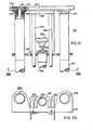
- Figure 1 is a view in front elevation of a tool or apparatus in accordance with a preferred embodiment of this invention, for the upper rolling of a sleeve;
- Figure 2 is a plan view of this tool taken in the direction II-II of Figure 1;
- Figure 3 is a view in transverse section taken along line III-III of Figure 1;
- Figure 4 is a view in transverse section taken along line IV-IV of Figure 1;
- Figure 5 is a view in transverse section taken along line V-V of Figure 1;
- Figure 6 is a view in section taken along line VI-VI of Figure 1;
- Figure 7 is a view in side elevation of the tool as seen from the right side of Figure 1;
- Figure 8 is a view in side elevation of the tool as seen from the left side of Figure 1;
- Figure 9 is a fragmental view partly in section and partly in side elevation showing the relationship of the tube and the mandrel of the apparatus shown in Figure 1;
- Figure 10 is a view in section taken along lines X-X of Figure 4;
- Figure 10A is a view in end elevation taken in the direction XA-XA of Figure 10;
- Figure 10B is a view in section taken along line XB-XB of Figure 10;
- Figure 10C is a view in section taken along line XC-XC of Figure 10i
- Figure 11 is a fragmental view partly in section and partly in side elevation taken in direction XI-XI of the lower part of Figure 10 and showing the lower part of the apparatus shown in Figure 1;
- Figure 12 is a view in side elevation of the tube-mandrel assembly of the apparatus shown in Figure 1;
- Figure 13 is a view in section enlarged of the portion of the assembly of Figure 12 in the circle XIII;
- Figure 14 is a fragmental view of the region of the tube of the apparatus shown in Figure 1 which includes the rolls;
- Figure 15 is a fragmental view showing a portion of a splined rod which guides the tube as it is raised or lowered,
- Figure 16 is a block diagram showing the limit or proximity switch circuit which controls the apparatus shown in Figure 1;
- Figure 16A is a block diagram showing a modification of this invention;
- Figure 17 is a plan view of the tool in accordance with this invention for the lower rolling;
- Figure 18 is a view in section taken along line XVIII-XVIII of Figure 17;
- Figure 19 is a view in section taken along line XIX-XIX of Figure 17;
- Figure 20 is a view in section taken along line XX-XX of Figure 17;
- Figure 21 is a view in section taken along line XXI-XXI of Figure 17;
- Figure 22 is a fragmental view in end elevation taken in the direction of line XXII-XXII of Figure 21; and
- Figure 23 is a fragmental view in section showing the mechanism which operates in response to the reactive torque of the hydraulic motor.
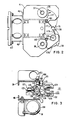
- Figures 1 through 16 show a tool or
apparatus 31 for rolling the upper region of asleeve 33 inserted in acoolant conductor 35 of a steam generator of a nuclear-reactor plant. Thecoolant conductor 35 extends into atube sheet 37. This apparatus includes a support formed ofchannel sections top plate 41 and abottom plate 43. Near the top, one channel supports a vertical plate 45 (Figure 7). Anadapter plate 47 is connected to thevertical plate 45 through atubular spacer 49. Theadapter plate 47 serves to suspend thetube 41 from the carriage of a coordinate transport (See Cooper). A fail-safe plate 50 is bolted below thelower plate 43. (Figure 8) This plate carries a limit switch (not shown) which stops the coordinate transport if the fail-safe plate 50 engages the wall of the channel head in which a coolant conductor is being rolled. -
Lockpin assemblies upper plate 41 externally of thechannels assembly cylinder 55 within which a piston (not shown) is movable. Each piston is connected through a piston rod (not shown) to alockpin 57 which extends through anopening 59 inplate 41. The locking pins 57 are advanced from, or retracted into,plate 41 depending on the direction of the supply of fluid into therespective cylinders 55. As disclosed in Cooper, thelockpins 57 are at the start of a rolling operation, injected intocoolant conductors 35, adjacent the coolant conductor to be rolled, and locked firmly in these adjacent conductors. - To carry out a rolling operation there is provided a
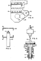
tube 61 having captive rolls 63 in the upper region thereof (Figures 12, 13, 14). Therolls 63 are normally retracted in the surface oftube 61 but are extensible by a taperedmandrel 65 which extends axially through thetube 61 coaxial with the tube. As shown in Figure 14, therolls 63 extend at an angle to the axis oftube 61. As the taperedmandrel 65 advances progressively intotube 61, therolls 63 extend more and more progressively outwardly from the surface of the tube. The mandrel has aconical nose 67 at the top to facilitate insertion into thetube 61. Thetube 61 is screwed into, and secured in, acollar 69 supported on athrust bearing 71 and is thus supported on the tube bearing (Figure 13). Themandrel 65 passes through thetube 61 and thebearing 71 and below the bearing has atang 72 which extends into a seat or chuck 73 (Figure 6). Near its lower end, the mandrel has agroove 75 into which aball bearing 77 extends through a hole in the seat. Theball 77 is releasably held in the groove by aninward projection 79 from asleeve 81. Thesleeve 81 is positioned so that it engages theball 77 by aspring 83 which is compressed between a shoulder onseat 73 and theprojection 79. The downward displacement of thesleeve 81 is limited by a retainingring 85. It is at times necessary to replace themandrel 65. On such occasions, thesleeve 81 is pressed upwardly against the force of thespring 85 releasing theball 77 and enabling the removal of the mandrel. Themandrel 65 can be adjusted vertically relative to thetube 61 by anadjustable bushing 87. Thebushing 87 may be screwed upwardly or downwardly on an externally-threadedannular member 89. Near its lower end the mandrel has a shoulder 90. The shoulder supports a sleeve 92 which carries athrust bearing 94. The assembly including themandrel 65, the shoulder 90, the sleeve 92 and thethrust bearing 94 is movable relative to thetube 61 and thebearing 71 so that the length of the sleeve 92 can be changed to vary the penetration of themandrel 65 intotube 61, the sleeve is made of two parts separated byspacer 96. - For rotating the mandrel 65 a
hydraulic motor 91 is provided. Themotor 91 drives the mandrel through aspeed reducer 93, a torque-responsiveclutch mechanism 95 and agear train 97. Themotor 91,gear reducer 93 andtorque mechanism 95 are mounted on abracket 96 connected to channel 40. Thegear train 97 includes agear 99 on the motor drive shaft, anidler gear 100 which meshes withgear 99 and agear 101.Gear 101 drives ashaft 103 of square cross section. Adriving gear 105 for themandrel 65 is mounted with itshub 107 slidable alongshaft 103. Thisgear 105 drives agear 109 connected to themandrel 65. The bearings (not shown) forgears carriage 121. In lieu of theshaft 103 of square cross section, a splined shaft of circular cross section may be used. In this case a key on thehub 107 would engage the spline slidably along the shaft. Thegears base 43 over the gears. The threaded member 89 (Figure 6) extends integrally from thehub 113 ofgear 107. Theshaft 103 rotates inbearings 115 and 117 in thetop plate 41 and the bottom plate 43 (Figure 10). - The assembly (Figure 1), including the
gears roll tube 61, thethrust bearing 71, themandrel 65 and the parts associated with the mandrel including thechuck 73, thesleeve 81 and thebushing 87, are mounted on acarriage 121. Thecarriage 121 is provided with a seat assembly 123 (Figure 3), which engages, and securely holds, thethrust bearing 71. The main support member of the carriage is anangle plate 124. Theseat assembly 123 includes arms or latches 126 (Figure 3) having, near their ends,seats 128 formed to engage the circular surface of thethrust bearing 71. Thearms 126 are pivotal manually in opposite directions on pivot pins 130 on the upper side ofangle plate 124. The angle plate carriespins 132 which are urged by springs (not shown) into grooves in the arms. The spring-pressedpins 132 hold the arms in the retracted position or in the position in which theseats 128 engage thebearing 71. A low-voltageelectric motor 127 drives thecarriage 121 upwardly or downwardly throughsprocket wheels chain 133. Themotor 127 is supported in abracket 135 secured to the channel 40 (Figure 8) just below theupper plate 41. The chain is maintained taut by atensioner 137. Abearing block 139 extends inwardly, with respect tochannels 39 and 40 (Figure 3), from the carriage 141. The bearing block carries abearing 143 which rides on avertical guide rod 145 for the carriage. At its lower end the bearing block is engageable by a stop collar 147 (Figure 7) which extends from thelower plate 43. The carriage is also maintained aligned byrollers carriage 121 and ride on theouter flanges 153 of thechannels 39 and 40 (Figure 3). - . Splined rod-
guides lower plates plate 41 and followguide holder 165 on the opposite side.Guide holder 165 is suspended from channel 40 (Figure 11).Bearings 166 and 168 are provided in theplate 43 and guideholder 165. Thesplines 169 are engaged bypins 171 secured in across member 173 of the carriage 121 (Figure 11). To facilitate removal of the splined guides 161, apin 171 in thespline 169 of one guide extends from a hand retractable plunger 180 (Figure 3); the other is held by aset screw 182. It is essential that theroll tube 61 be aligned with thesleeve 33 which it is to roll. This alignment is accomplished byfingers guide fingers 177 extending from the foot and encircling thetube 61. Above (to the left or right of) the knee each guide encircles and engages a correspondingsplined guide rod fingers Guide 178 includes a loop aroundshaft 103.Finger 175 extends over a large angle of the periphery oftube 61;finger 176 extends over a smaller angle (Figure 2). Eachspline 169 extends directly in an axial direction from the top to a point spaced a predetermined distance from the bottom. Theportion 179 of thespline 169 from the point extends at an angle to the axis (Figure 15). With thecarriage 121 in the lower-most position, the finger guides 177 and 178 are set so that thefingers tube 61 and maintain the tube aligned. As thecarriage 121 is raised from the lowermost position, thepins 171 coact with thespline portions 179, which operate as cams, to rotate therods guides carriage 121. When thecarriage 121 is at the position where thefingers roll tube 61 is well within thesleeve 33 and is maintained aligned by the sleeve. Thecarriage 121 can now be advanced without interference from theguides coolant conductor 35 being sleeved which extends from thetube sheet 37. In this position oftube 61, therolls 63 are the level of the region ofsleeve 33 which is to be rolled. - The
mandrel 65 is advanced into thetube 61, to extend and rotate therolls 63 by a low-voltageelectric motor 181 which is mounted on thecarriage 121. The drive shaft of themotor 181 carries apinion 183 which engages arack 185 supported onbracket 187 secured tocarriage 121. When themotor 181 is energized, thepinion 183 is driven alongrack 185 carrying with it the table 110, thegears mandrel 65 and its associated parts. Withhydraulic motor 91 energized, thedrive gear 107 is rotated bysquare shaft 103 drivingshaft 109 and rotating the mandrel. - In the practice of this invention proximity limit switches are provided to initiate the successive steps of operation (Figure 16) responsive to the positioning of the
roll tube 61 and themandrel 65. The proximity switches are operated by magnets carried by thecarriage 121 and by parts movable with themandrel 65. - The operation of the apparatus is initiated by a command from computer 191 (Figure 16; see also Cooper) impressed on the hydraulic servo control (HSC) 193. Through the HSC the
motor 127 is energized, raising thecarriage 121 and thetube 61 andmandrel 65 and the other parts mounted on the carriage. When thecarriage 121 is raised to the position at whichcollar 69 abuts the end of thecoolant conductor 35 being sleeved,proximity switch 195 is actuated bymagnet 197 which moves with carriage 121 (Figures 10, 10A).Switch 195 is suspended belowplate 41 by angle 199.Magnet 197 is carried on a block 201 secured tocarriage 121. Actuation ofswitch 195 transmits a signal to thecomputer 191. The computer commands the HSC to deenergizemotor 127 and to energize thehydraulic motor 91 andmotor 181. The taperedmandrel 65 advances into thetube 61 extending therolls 63 progressively in higher and higher pressure-contact with the sleeve. At the same time themandrel 65 rotates rotating therolls 63. Below thethrust bearing 71 there is the thrust bearing 94 which is carried by sleeve 92 in themandrel 65. As the mandrel penetrates into tube 61 a shoulder 90 on the mandrel raises thebearing 94 until it contacts bearing 71. At this point the penetration of the mandrel into the tube is stopped. The mandrel and bearing 94 are shown in the retracted position in Fig. 1 and in the advanced position in Fig. 12. - On being actuated by
switch 195 thecomputer 191 starts timing of a time interval which is usually longer than the time taken for bearing 94 to contactbearing 71. At the end of the interval thecomputer 191 commands theHSC 193 to reversehydraulic motor 91 andmotor 181. The direction of rotation of themandrel 65 is reversed and the mandrel is retracted or withdrawn from thetube 61. The reversal of the direction of rotation of the mandrel facilitates its retraction. Typically themotor 181 does not have sufficient power to retract themandrel 65 without the aid of the reversal. The time interval is set so as to preclude excessive heating of the sleeve and tube. The blowout is precluded by the limitation of bearing 94 of the penetration of the mandrel. The rolling should form a mechanical seal, between the rolled portion of the sleeve and the contiguous portion of the coolant conductor which effectively, prevents the penetration of coolant between the sleeve and coolant conductor. - The penetration of the
mandrel 65 into thetube 61 is also monitored by a proximity switch. This switch is adjustable along a part 192 (Figure 16A) carried by thecarriage 121 with respect to which themandrel 65 is movable. Apart 196 carried with thepinion 183, which moves generally parallel to the part on which theadjustable switch 192 is mounted, carries amagnet 198 which actuates the adjustable switch when themandrel 65 has penetrated to the desired position in thetube 61. Themotors - A
proximity switch 203 is also mounted on a mounting block 205 (Figure 10C). This switch is actuable by amagnet 207 movable with thepinion 183. When themandrel 65 reaches a lower level at whichmagnet 207 actuatesswitch 203, the computer responds to the signal from this switch by commanding the HSC to deenergizemotors motor 127. Thecarriage 121 is moved downwardly removing thetube 61 from thesleeve 33. With themandrel 65 withdrawn and therolls 63 retracted, the tube is readily removed from the sleeve. - A
proximity switch 211 is mounted on an angle 213 secured tolower plate 43. When thecarriage 121 reaches its lowermost position,magnet 197 actuateslimit switch 211deenergizing motor 127 and otherwise resetting the apparatus. The rolling operation is now completed. Thesleeve 33 is rolled typically over a length of 1-1/2 inches. - Figures 17 through 23 show the tool or
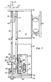
apparatus 221 for low rolling of asleeve 33 in acoolant conductor 35. This apparatus includes a support formed ofchannels channels channels plate 228 hasguide holes 230 for the fluid and electrical cables which serve thetool 221 and large elongated holes permitting access to the underside of the tool. Avertical plate 229 is secured acrossmembers top plate 227 to a point below the horizontal center plane of thetool 221. Theplate 229 serves to suspend theapparatus 221 from the coordinate transport (described in Cooper) when the apparatus is to carry out a low rolling operation. - Near each of its ends along its width in the front portion, the
top plate 227 is provided with a housing 231 for suspending a lockpin assembly 233 (Figure 21). This housing 231 includes an internally threadedflanged sleeve 235 secured to theplate 227 bypins 237 extending from aring 239 abutting theplate 227. The pins extend through the flange of thesleeve 235. Thelockpin assembly 233 includes acylinder 241 within which a piston (not shown) is moved upwardly or downwardly by a fluid. The piston rod (not shown) attached to the piston moves a lockpin 243 upwardly or downwardly. An externally threadedshell 245 extending from thecylinder 241 is screwed into thesleeve 235 and is secured by anut 247 and locked againstring 239. The lockpins are inserted by upward movement of the piston and locked in coolant conductor adjacent to theconductor 33 being rolled and preclude the disengagement of thetool 221 from the sleeve during rolling by the reactive forces exerted in the tool. The desired location of the lockpin assembly may be set by inserting thepins 237 in different holes. As shown in Figure 22 such adjustment is feasible because theholes 238 intop plate 227 are of larger diameter than thecylinders 241. - In the upper part of the
apparatus 221, a channel bracket 251 is supported from theflanges 253 of thechannels bracket 259 for a spray nozzle (not shown) for cooling theroll tube 261 and themandrel 263 between successive rolling operations. Guide rods 265 (Figures 17, 18, 21) are secured to thelower flange 267 of the channel bracket 251, by rod clamps 268 (Figure 22) and extend into theupper flange 269. - The
roll tube 261 and the taperedmandrel 263 are supported on avertical carriage 271 having an angular structure.Latches 273 are pivotal onpins 275 on thehorizontal member 277 of the carriage. Spring actuable pins 279 extend into grooves in the stems of thelatches 273. Thelatches 273 are pivotal between a retracted position and a position in which they engage the thrust bearing 281 which supports theroll tube 261. -
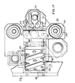
Plate assemblies 283 and 285 extend rearwardly from thevertical member 287 of thecarriage 271. With reference to Figure 18, the front of thetool 221 is on the right. The word rear refers to regions leftward of the front. Eachassembly 283 and 285 carriesball bushings respective guide rods 265. Eachbushing rings 295. Thelower plate assembly 283 serves only as a mounting forbushings 289. The upper plate assembly 285 serves as a mounting forbushings 291 and in addition is connected to thepiston rod 297 from the piston (not shown) inhydraulic cylinder 299. The fluid incylinder 299 movespiston rod 297 upwardly or downwardly driving thecarriage 271 and theroll tube 261 andmandrel 263 upwardly or downwardly through the plate assembly 285. The plate assembly 285 also carries amagnet 301 which operatesswitches carriage 271 in the fully-up or fully-down position. Thepiston 299 is suspended fromplate 267. - A
plate 303, extending towards the front of thetool 221, is supported onvertical member 287 below its center.Plate 303 supports a ball bearing 305 (Figures 18, 19) in which ahollow drive shaft 307 is rotatable. Externally the drive shaft carrieskeyways 309 along its length. Internally,drive shaft 307 is of square transverse cross section. Thekeyways 309 are engaged bykeys 311 extending from adrive sleeve 312 rotatable bygear 313 onball bearings 315 held byretainer ring 317. The square boundary of thedrive shaft 307 is engaged by atang 319. At its top this tang carries achuck 321 which is engaged by asquare tang 323 on the lower end of themandrel 263. Thetang 319 and the chuck which it carries are rotatable inball bearings 325 carried byplate 327 when thedrive shaft 307 is rotated. Thetang 319 is held by a ball (not shown) which is held in agroove 329 in the tang by asleeve 331 urged upwardly by a spring 333. By pressing the sleeve downwardly the ball is disengaged fromgroove 329 releasing themandrel 263 so that it may be removed or replaced. - Guide rods 335 (Figure 20) are mounted between
plate 303 and thehorizontal member 277 of thecarriage 271. Theplate assembly 327 is provided withball bushings 337. Theball bushings 337 engagerods 335.Plate assembly 327 is movable along these rods on these bushings. As it is moved upwardly ordownwardly plate assembly 327 carries with ittang 319 and themandrel 263 and its associated parts. These parts are rotatable bydrive shaft 307 while they move upwardly or downwardly. The upward or downward movement ofplate 327 and the parts attached to it is effected by a piston (not shown) driven byair cylinder 339. This cylinder is supported on thevertical member 287. -
Gear 313 is driven by hydraulic motor 341 (Figure 19) through a train ofgears gears 313 through 349 are mounted in agear casing 351 supported on abracket 353 suspended from theflanges 253 of thechannels 223 and 225 (Figure 18). - To carry out a rolling operation, the
hydraulic cylinder 299 is supplied with fluid to raisecarriage 271 andtube 261 andmandrel 263 and their associated parts so thattube 261 penetrates into thesleeve 33 within the tube sheet. Plate assembly 285 is raised withcarriage 271. When magnet 301 (Figure 18) is nearproximity switch 257,pneumatic cylinder 339 is actuated andmotor 341 is energized. While the motor rotatesmandrel 263, it is advanced intotube 261 extending therolls 361 into thesleeve 33 and rolling the sleeve. -
Motor 341 has a torque responsive mechanism 363 (Figure 23). This mechanism includes anactuating bracket 365 which is held retracted by aspring 367 wheremotor 341 is deenergized. As therolls 361 are extended progressively into thesleeve 33 by the taperedmandrel 263, the reactive torque on themotor 341 is increased.Bracket 365 advances leftward against the pressure ofspring 367.Sensing finger 369 is pivoted in a counterclockwise direction with reference to Figure 23.Finger 369 is linked to switch-actuating arm 371 and pivots this arm counterclockwise, closingmicroswitch 373 when the reactive torque produced by the pressure ofrolls 361 onsleeve 33 reaches a predetermined magnitude. The magnitude may be set byadjustment screw 375. - When
switch 373 is closed, thehydraulic motor 341 is reversed and the air incylinder 339 is supplied in a direction such as to retractmandrel 263 fromtube 361. When the mandrel reaches its lowermost position aproximity switch 376 is actuated by amagnet 378 reversing the movement of the piston incylinder 299, movingcarriage 271 downwardly and retracting to rolltube 261. The actuation of switch 276 also stopsmotor 341. When thecarriage 271 reaches itslowermost position magnet 301 actuatesswitch 258 and the rolling operation is completed. The proximity switches 257 and 258 and theswitch 373 operate throughcomputer 191 in the same manner as the control components for the upper rolling. Theswitch 373 transmits the intelligence that it has been closed to thecomputer 191. The computer commands the mandrel retracting operation. During theretraction switch 373 is opened without affecting the progress of the retraction operation. - While several embodiments of this invention have been disclosed herein, many modifications thereof are feasible. This invention should not be restricted except insofar as is necessitated by the spirit of the prior art.
Claims (10)
Applications Claiming Priority (2)
| Application Number | Priority Date | Filing Date | Title |
|---|---|---|---|
| US538320 | 1983-10-03 | ||
| US06/538,320 US4586250A (en) | 1983-10-03 | 1983-10-03 | Apparatus for sleeving tubes in hostile environments |
Publications (2)
| Publication Number | Publication Date |
|---|---|
| EP0140586A2 true EP0140586A2 (en) | 1985-05-08 |
| EP0140586A3 EP0140586A3 (en) | 1986-12-30 |
Family
ID=24146425
Family Applications (1)
| Application Number | Title | Priority Date | Filing Date |
|---|---|---|---|
| EP84306624A Ceased EP0140586A3 (en) | 1983-10-03 | 1984-09-28 | Sleeving of tubes in hostile environments |
Country Status (7)
| Country | Link |
|---|---|
| US (1) | US4586250A (en) |
| EP (1) | EP0140586A3 (en) |
| JP (1) | JPS6096805A (en) |
| KR (1) | KR920004661B1 (en) |
| CA (1) | CA1240491A (en) |
| ES (1) | ES8607073A1 (en) |
| ZA (1) | ZA847414B (en) |
Cited By (4)
| Publication number | Priority date | Publication date | Assignee | Title |
|---|---|---|---|---|
| EP0309078A3 (en) * | 1987-09-24 | 1990-10-24 | Foster Wheeler Energy Corporation | Method of apparatus for expanding and sealing a sleeve into a surrounding tube |
| GB2338441A (en) * | 1998-06-16 | 1999-12-22 | Teddington Centreless Grinding | Mandrel |
| CN101954566A (en) * | 2010-05-19 | 2011-01-26 | 张家港市恒强冷却设备有限公司 | Process for fixedly connecting titanium cooling tube in cooler and radiating fins and titanium tube plate |
| AU2008261261B2 (en) * | 2007-06-13 | 2013-06-27 | Csl Behring Gmbh | Use of VWF stabilized FVIII preparations and of VWF preparations without FVIII for extravascular administration in the therapy and prophylactic treatment of bleeding disorders |
Families Citing this family (12)
| Publication number | Priority date | Publication date | Assignee | Title |
|---|---|---|---|---|
| US4688327A (en) * | 1983-10-03 | 1987-08-25 | Westinghouse Electric Corp. | Sleeving of tubes of steam generator |
| US4679377A (en) * | 1984-12-05 | 1987-07-14 | Westinghouse Electric Corp. | Apparatus for applying an end plug to an end of a fuel rod tube |
| US4672791A (en) * | 1984-12-05 | 1987-06-16 | Westinghouse Electric Corp. | Apparatus for applying an end plug to an end of a fuel rod tube |
| US4771526A (en) * | 1985-10-07 | 1988-09-20 | Westinghouse Electric Corp. | Sleeving of steam generators |
| US4713952A (en) * | 1986-02-05 | 1987-12-22 | Westinghouse Electric Corp. | Tool and method for rotopeening the peripheral tubes in a tubesheet |
| US4722122A (en) * | 1986-04-18 | 1988-02-02 | Combustion Engineering, Inc. | Rotation station for remotely installing mechanical tube plugs |
| FR2598202B1 (en) * | 1986-04-30 | 1990-02-09 | Framatome Sa | METHOD FOR COVERING A PERIPHERAL TUBE OF A STEAM GENERATOR. |
| US4829648A (en) * | 1987-01-27 | 1989-05-16 | Westinghouse Electric Corp. | Apparatus and method for simultaneously loading a reinforcing sleeve and mandrel into a tube |
| FR2630365B1 (en) * | 1988-04-25 | 1990-07-13 | Stein Industrie | INTERNAL SLEEVING MACHINE WITH SLEEVE OF THE END OF HEAT EXCHANGER TUBES |
| US4835828A (en) * | 1988-09-22 | 1989-06-06 | American Standard Inc. | Automatic tube expander for a heat exchanger |
| US5029388A (en) * | 1988-12-08 | 1991-07-09 | Westinghouse Electric Corp. | Apparatus and process for sleeving the heat exchanger tubes of nuclear steam generators |
| CN104801903A (en) * | 2015-04-21 | 2015-07-29 | 常熟锐钛金属制品有限公司 | Device for welding titanium tube and stainless steel tube plate |
Family Cites Families (14)
| Publication number | Priority date | Publication date | Assignee | Title |
|---|---|---|---|---|
| US1987608A (en) * | 1931-07-02 | 1935-01-15 | E T Hargrove | Tube expanding |
| US2355852A (en) * | 1943-06-08 | 1944-08-15 | Frank F Fisher | Tube expanding tool |
| GB765066A (en) * | 1954-01-27 | 1957-01-02 | Airetool Mfg Company | Electric circuit for tube expander and method of operation |
| US3059688A (en) * | 1960-11-23 | 1962-10-23 | Harry P Colbert | Multiple shaft tool head |
| FR1290917A (en) * | 1961-03-06 | 1962-04-20 | Brevets Wagner Soc D | Sophisticated tool to expand |
| US3688533A (en) * | 1970-10-19 | 1972-09-05 | Tridan Tool & Machine | Tube expansion apparatus |
| US3683481A (en) * | 1971-03-10 | 1972-08-15 | Vernon Tool Co Ltd | Apparatus for expanding tubes |
| US3854314A (en) * | 1973-07-25 | 1974-12-17 | Dresser Ind | Step controlled tube expander |
| DE2709633C3 (en) * | 1976-03-26 | 1981-04-23 | Combustion Engineering, Inc., 06095 Windsor, Conn. | Device for fastening a sleeve in a pipeline |
| US4186584A (en) * | 1978-05-24 | 1980-02-05 | Thomas C. Wilson, Inc. | Tube expander |
| US4216569A (en) * | 1978-11-30 | 1980-08-12 | Westinghouse Electric Corp. | Method for installing a tube in a heat exchanger tube sheet |
| US4235013A (en) * | 1978-10-30 | 1980-11-25 | Westinghouse Electric Corp. | Tube guide-expander |
| US4319472A (en) * | 1980-03-07 | 1982-03-16 | Carrier Corporation | Tube end expander and method of operating the same |
| US4407150A (en) * | 1981-06-08 | 1983-10-04 | Haskel Engineering & Supply Company | Apparatus for supplying and controlling hydraulic swaging pressure |
-
1983
- 1983-10-03 US US06/538,320 patent/US4586250A/en not_active Expired - Fee Related
-
1984
- 1984-09-20 ZA ZA847414A patent/ZA847414B/en unknown
- 1984-09-28 EP EP84306624A patent/EP0140586A3/en not_active Ceased
- 1984-10-01 CA CA000464414A patent/CA1240491A/en not_active Expired
- 1984-10-02 JP JP59207910A patent/JPS6096805A/en active Pending
- 1984-10-02 KR KR1019840006103A patent/KR920004661B1/en not_active Expired
- 1984-10-03 ES ES536453A patent/ES8607073A1/en not_active Expired
Cited By (4)
| Publication number | Priority date | Publication date | Assignee | Title |
|---|---|---|---|---|
| EP0309078A3 (en) * | 1987-09-24 | 1990-10-24 | Foster Wheeler Energy Corporation | Method of apparatus for expanding and sealing a sleeve into a surrounding tube |
| GB2338441A (en) * | 1998-06-16 | 1999-12-22 | Teddington Centreless Grinding | Mandrel |
| AU2008261261B2 (en) * | 2007-06-13 | 2013-06-27 | Csl Behring Gmbh | Use of VWF stabilized FVIII preparations and of VWF preparations without FVIII for extravascular administration in the therapy and prophylactic treatment of bleeding disorders |
| CN101954566A (en) * | 2010-05-19 | 2011-01-26 | 张家港市恒强冷却设备有限公司 | Process for fixedly connecting titanium cooling tube in cooler and radiating fins and titanium tube plate |
Also Published As
| Publication number | Publication date |
|---|---|
| ES8607073A1 (en) | 1986-05-16 |
| CA1240491A (en) | 1988-08-16 |
| ES536453A0 (en) | 1986-05-16 |
| KR850003280A (en) | 1985-06-13 |
| US4586250A (en) | 1986-05-06 |
| KR920004661B1 (en) | 1992-06-13 |
| JPS6096805A (en) | 1985-05-30 |
| EP0140586A3 (en) | 1986-12-30 |
| ZA847414B (en) | 1985-08-28 |
Similar Documents
| Publication | Publication Date | Title |
|---|---|---|
| EP0140586A2 (en) | Sleeving of tubes in hostile environments | |
| EP0037135B1 (en) | Pallet transfer system | |
| US4483223A (en) | Portable lathe | |
| CA2686595C (en) | Method and apparatus for removing pressure tubes from nuclear reactors | |
| US4840096A (en) | Device for machining chamfers on a free of a pipe | |
| CA1264110A (en) | Suspension of tools for sleeving of tubes of steam generator | |
| US4724607A (en) | Apparatus for rebuilding nuclear fuel assemblies | |
| US4399603A (en) | Power grip tool exchange arm for machining center | |
| CN106077741A (en) | A kind of multi-functional full-automatic relief valve processing rig | |
| EP0300230A2 (en) | Method of repairing rolls of rolling mill and roll cutting apparatus | |
| WO2022142140A1 (en) | Graphite radioactivity measurement device, sampling apparatus, and sampling method | |
| US4829660A (en) | System for removing a plug from a heat exchanger tube | |
| CA1240625A (en) | Sleeving of tubes of steam generator in hostile environment | |
| JPH0366530A (en) | Method and device for removing closing plug from tube of steam generator | |
| US4624042A (en) | Robotic clamp and index tool and method for their use in repairing certain elements with in a nuclear reactor | |
| GB2129350A (en) | Remotely controllable cutting apparatus | |
| US5165470A (en) | Plugging apparatus for heat exchanger | |
| US4559682A (en) | Machine tool with swiveling head | |
| JP2004347349A (en) | Underwater demolition equipment | |
| US4782727A (en) | Process of replacing a sleeve mounted within a pipe, and devices for carrying out that process | |
| US4178787A (en) | Remotely operated tube expanding tool and support | |
| US3707758A (en) | Installation for mounting sealing rings and the like, especially for radioactive enclosures | |
| EP0594381B1 (en) | Control blade servicing assembly | |
| JPH01296197A (en) | Separation and separator for end piece of nuclear fuel assembly | |
| JP2984550B2 (en) | Thermal sleeve drilling device for reactor vessel top nozzle |
Legal Events
| Date | Code | Title | Description |
|---|---|---|---|
| PUAI | Public reference made under article 153(3) epc to a published international application that has entered the european phase |
Free format text: ORIGINAL CODE: 0009012 |
|
| AK | Designated contracting states |
Designated state(s): BE CH FR GB IT LI SE |
|
| PUAL | Search report despatched |
Free format text: ORIGINAL CODE: 0009013 |
|
| AK | Designated contracting states |
Kind code of ref document: A3 Designated state(s): BE CH FR GB IT LI SE |
|
| 17P | Request for examination filed |
Effective date: 19870626 |
|
| 17Q | First examination report despatched |
Effective date: 19880601 |
|
| STAA | Information on the status of an ep patent application or granted ep patent |
Free format text: STATUS: THE APPLICATION HAS BEEN REFUSED |
|
| 18R | Application refused |
Effective date: 19900419 |
|
| RIN1 | Information on inventor provided before grant (corrected) |
Inventor name: VOGELEER, JOHN PIERRE Inventor name: COOPER, FRANK WILLIAM, JR. |