EP0299338A2 - Defibrillator - Google Patents
Defibrillator Download PDFInfo
- Publication number
- EP0299338A2 EP0299338A2 EP88110738A EP88110738A EP0299338A2 EP 0299338 A2 EP0299338 A2 EP 0299338A2 EP 88110738 A EP88110738 A EP 88110738A EP 88110738 A EP88110738 A EP 88110738A EP 0299338 A2 EP0299338 A2 EP 0299338A2
- Authority
- EP
- European Patent Office
- Prior art keywords
- voltage
- circuit
- capacitor
- charge
- defibrillator
- Prior art date
- Legal status (The legal status is an assumption and is not a legal conclusion. Google has not performed a legal analysis and makes no representation as to the accuracy of the status listed.)
- Granted
Links
Images

Classifications
-
- A—HUMAN NECESSITIES
- A61—MEDICAL OR VETERINARY SCIENCE; HYGIENE
- A61N—ELECTROTHERAPY; MAGNETOTHERAPY; RADIATION THERAPY; ULTRASOUND THERAPY
- A61N1/00—Electrotherapy; Circuits therefor
- A61N1/18—Applying electric currents by contact electrodes
- A61N1/32—Applying electric currents by contact electrodes alternating or intermittent currents
- A61N1/38—Applying electric currents by contact electrodes alternating or intermittent currents for producing shock effects
- A61N1/39—Heart defibrillators
- A61N1/3925—Monitoring; Protecting
- A61N1/3937—Monitoring output parameters
-
- A—HUMAN NECESSITIES
- A61—MEDICAL OR VETERINARY SCIENCE; HYGIENE
- A61N—ELECTROTHERAPY; MAGNETOTHERAPY; RADIATION THERAPY; ULTRASOUND THERAPY
- A61N1/00—Electrotherapy; Circuits therefor
- A61N1/18—Applying electric currents by contact electrodes
- A61N1/32—Applying electric currents by contact electrodes alternating or intermittent currents
- A61N1/38—Applying electric currents by contact electrodes alternating or intermittent currents for producing shock effects
- A61N1/39—Heart defibrillators
- A61N1/3904—External heart defibrillators [EHD]
-
- A—HUMAN NECESSITIES
- A61—MEDICAL OR VETERINARY SCIENCE; HYGIENE
- A61N—ELECTROTHERAPY; MAGNETOTHERAPY; RADIATION THERAPY; ULTRASOUND THERAPY
- A61N1/00—Electrotherapy; Circuits therefor
- A61N1/18—Applying electric currents by contact electrodes
- A61N1/32—Applying electric currents by contact electrodes alternating or intermittent currents
- A61N1/38—Applying electric currents by contact electrodes alternating or intermittent currents for producing shock effects
- A61N1/39—Heart defibrillators
- A61N1/3925—Monitoring; Protecting
- A61N1/3931—Protecting, e.g. back-up systems
Definitions
- the present invention relates to a defibrillator in which a high-voltage generating circuit charges a high-voltage capacitor circuit with a high voltage, and which is adapted to apply the charged high voltage by an electrode or a paddle to a body of a patient by turning on or closing an output switch.
- such a high-voltage capacitor circuit is formed by a capacitor in which the electrodes are of a metal-film type and the terminals have a tab structure with which lead wires can be inserted. Accordingly, such a capacitor tends to be bulky as a high-voltage capacitor and raises problems concerning its durability because the lead wires are subjected to stress during the discharge of large-magnitude currents.
- a metallized plastic film capacitor In order to solve these problems, one may alternatively use a metallized plastic film capacitor. In this case, however, one has to cope with the problem that such a capacitor may have a self-healing ability. That is, because of this self-healing ability, if a dielectric breakdown takes place in the high-voltage capacitor circuit, the capacitor does not become unusable automatically and can be charged again with the high voltage which, however, is lower than a prescribed and necessary high voltage. The capacitor is thus maintained in a usable condition but it remains unstable.
- the electrodes are composed of deposited layers and the lead wires extend from metallic contact or metal sprayed portions at both ends of wound-up films.
- the object underlying the present invention is to provide a defibrillator which is more reliable in operation and capable of automatically detecting a dielectric breakdown of the high-voltage capacitor circuit and of stopping operation of the device.
- Another object of the present invention is to provide a high-voltage capacitor circuit comprising a metallized plastic film capacitor which is very suitable for use in a defibrillator
- a high-voltage capacitor circuit consists of a metallized plastic film capacitor. Further components of the defibrillator are a charge abnormality detecting circuit for detecting a sharp increase in charge current and/or a sharp drop in charge voltage which are caused by a dielectric breakdown of the metallized plastic film capacitor, a notifying means for notifying any abnormality in response to a detection signal of the detecting circuit, and a switch circuit for inhibiting the further supply of a high voltage to the high-voltage capacitor circuit, namely in response to the detection signal, either by blocking the voltage input to or the output from the high-voltage generating circuit or by stopping the operation of the high-voltage generating circuit.
- This arrangement makes it possible to detect and notify any dielectric breakdown of the high-voltage capacitor circuit. Therefore, even if a metallized plastic film capacitor is used in the high-voltage capacitor circuit, it is possible to eliminate the prior art problem that, on account of the self-healing characteristics, the capacitor is re-charged with an insufficiently high voltage and is then operated in its unstable condition
- the metallized plastic film capacitor circuit comprises a plurality of capacitor elements each of which have metallized plastic films wound up, and metallic contacts provided on the end surfaces on both sides thereof Resistors each of which have a resistance at least equal to the internal resistance of each capacitor element per se are connected to metallic contact portions of the capacitors elements.
- the high-voltage capacitor circuit for the defibrillator is made compact. Further, since the capacitor circuit is divided into a plurality of capacitor elements, the number of times the thin metal layers must be wound is reduced, thereby facilitating manufacture while improving the reliability after manufacture.
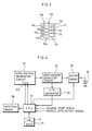
- a defibrillator which is known in principle is composed of a high-voltage generating circuit 1, a high-voltage capacitor circuit 2 adapted to be charged with a high-voltage by the high-voltage generating circuit 1, and an output circuit 3 including at least a switch for applying a high voltage to an electrode or a paddle 4 to be mounted on a body of a patient.
- Various structures may be used for each of the respective components as explained hereinafter.
- the high-voltage capacitor circuit 2 comprises a metallized plastic film capacitor.
- the basic circuit arrangement according to Fig.1 further comprises a charge abnormality detecting circuit 5 connected to the high-voltage capacitor circuit 2 and to a switch circuit 1a of the high-voltage generating circuit 1 for detecting a sharp increase of the charge current and/or a sharp drop of the charge voltage which are caused by a dielectric breakdown of the metallized plastic film capacitor, and indicating or notifying means 6 connected to the charge abnormality detecting circuit 5 for notifying any abnormality in response to a detection signal of the detecting circuit 5 by emitting light and/or sound.
- the switch circuit 1a is provided for inhibiting the feeding of a high voltage to the high-voltage capacitor circuit 2 in response to a corresponding detection signal from the detecting circuit 5 by blocking the voltage input to or the output from the high-voltage generating circuit 1 or by stopping the operation of the high-voltage generating circuit 1.
- the charge abnormality detecting circuit 5 detects an abnormality in charging during a charging process or in the charged condition after the completion of charging. By this detection, the switch circuit 1a is operated and inhibits the feeding of a high voltage to the metallized plastic film capacitor, thereby preventing the capacitor from being re-charged by its self-healing ability.
- the notifying means 6 notifies the dielectric breakdown of the capacitor circuit 2 to the operator, thus enabling the capacitor circuit to be replaced, and thereby eliminating the risk that a self-healed capacitor is used furtheron in its condition having a reduced capacity.
- Fig. 2 shows a circuit arrangement of a defibrillator in accordance with a second and specific embodiment of the present invention.
- the arrangement of a defibrillator is such that a high-voltage capacitor circuit 11 is charged by a high-voltage generating circuit 10, and, when a switch 12 is turned on or closed, the charge voltage of the high-voltage capacitor circuit 11 is applied to an electrode or a paddle 14 via an inductance 13.
- the defibrillator is provided with a charge abnormality detecting circuit.
- This charge abnormality detecting circuit comprises a voltage divider 15 connected in parallel to the high-voltage capacitor circuit 11, a peak holding circuit 16 to which a fraction voltage of the voltage divider 15 is input, and a comparator circuit 17.
- the inputs of a comparator 17 are connected to the output of the peak holding circuit 16 and to the input of the peak holding circuit 16 supplied with a signal from the tap of the voltage divider 15.
- the comparator circuit 17 receives a control signal from a switch 12 connected between the high-voltage generating circuit 10 and the inductance 13.
- the holding voltage of the peak holding circuit 16 is input to the comparator circuit 17 which is adapted to generate a signal when the fraction voltage of the voltage divider 15 drops below a predetermined value, for example 3/4 of the holding voltage.
- the output of the comparator circuit 17 is supplied to an LED 18 for indicating or notifying any abnormality, and simultaneously it is used to drive a switch 19 for blocking the voltage input to the high-voltage generating circuit 10.
- the high-voltage capacitor circuit 11 has a plurality of capacitor elements 11a received in a common case 11d.
- Each of the capacitor elements 11a is formed of metallized plastic films wound up and is provided with metallic contacts at the ends on both sides thereof.
- the metallic contact portions at the ends on either side of the capacitor elements 11a are connected to either one of a pair of capacitor terminals 11b extending from the case 11d.
- All the capacitor elements 11a are connected in parallel to each other and connected between the pair of capacitor terminals 11b.
- the arrangement of this capacitor circuit 11 is such that a plurality of resistors 11c are provided each of which have at least the same resistance as the internal resistance of each capacitor element 11a per se, and are interposed in series each between the metallic contact portions provided on the ends on one side of the respective capacitor elements 11a and the corresponding terminal 11b.
- the comparator circuit 17 is kept inoperative during a discharging period so as to prevent the comparator circuit 17 from being erroneously actuated by a drop in voltage during the discharge of the charge voltage via the electrode or the paddle 14 to the body of a patient when the switch 12 has been closed.
- defibrillator The operation of defibrillator is as follows: The voltage of the capacitor circuit 11 rises with a saw-tooth waveform while the capacitor circuit 11 is being charged so that the holding voltage of the peak holding circuit 16 is sequentially regenerated and the peak holding 16 holds a voltage corresponding to the charge voltage. Therefore, during a charging period, signals input to the terminals of the comparator circuit 17 are at substantially the same level and the comparator circuit 17 generates no signal.
- the switch 12 When the switch 12 is closed or turned on after the completion of charging, the charge voltage is discharged to the body of a patient via corresponding electrodes or the so-called paddle 14. During this discharging period, a control signal is supplied from the switch 12 to the comparator circuit 17 so that the comparator circuit 17 will not detect any difference from the holding voltage.
- the dielectric breakdown causes a sharp drop in the charge voltage so that the fraction voltage at the voltage divider is reduced to a value which is lower than a predetermined value, for example lower than a 3/4-value of the peak-holding voltage.
- the comparator circuit 17 outputs a detection signal.
- the LED 18 is turned on to notify the dielectric breakdown of the capacitor circuit 11 and, simultaneously, the switch 19 is operated to interrupt the generation of a high voltage. In this way, the capacitor circuit 11 is positively prevented from being re-charged due to its self-healing characteristics.
- the capacity of the capacitor circuit 11 corresponds to that of the capacitor elements 11a connected in parallel.
- the charge abnormality detecting circuit may alternatively be such that the capacitor circuit 11 is connected to, instead of the voltage divider 15, serially connected resistors having a small resistance which are provided for detecting the charge current, wherein a differentiation circuit is adapted to detect a sharp increase in current.
- FIG. 4 illustrates another embodiment of the present invention.
- a defibrillator comprises a high-voltage generating circuit 21, a high-voltage capacitor circuit 22, an output circuit 23, an electrode or a paddle 24, and a CPU 25 provided for control purposes.
- the CPU 25 is used in the following manner. A fraction of a high voltage which has been digitized by an A/D converter 26 is fed to the CPU 25 to be compared, as time passes by, with data D of curves which are stored in a ROM 27 expressing and corresponding to the operation of normal charging and discharging (to a patient).
- a detection is effected detecting a dielectric breakdown.
- the detection of such a dielectric breakdown is also possible during the discharge of the charge voltage to the body of a patient.
- operations similar to those described above are performed, that is, a switch 21a inhibits the further supply of a high voltage by the high-voltage generating circuit 21, while a notifying means 28 notifies the dielectric breakdown.
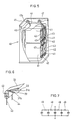
- Fig. 5 shows a winding structure of a high-voltage capacitor circuit 40 in accordance with the present invention, the capacitor circuit 40 being similar to the above-described high-voltage capacitor circuit 11.
- the capacitor circuit 40 comprises, for instance, four capacitor elements 41 each of which are formed by winding up metallized plastic films 31a and 31b on which layers 32 of a metal, e.g. aluminum, are deposited, with protective films 33 being inserted between the films, in such a manner as to provide non-deposited portions at both lateral ends of the capacitor element (see Fig. 6).
- Metallic contacts 42 are provided on the end surfaces of each capacitor element 41 on both sides thereof. Resistance wires 43 are soldered to the end surfaces of the capacitor elements 41 on one side, while a lead wire 44 is soldered to the end surfaces on the other side so as to connect the capacitor elements 41 in parallel.
- All the four capacitor elements 41 are surrounded by a pressed board 46 and are sealed within a case 45 filled with insulating oil.
- the resistance wires 43 are connected to one terminal 47 of a pair of terminals 47, 47a formed on the upper surface of the case 45, while the single lead wire 44 extending from the junctions of the parallel connection is connected to the other terminal 47a.
- Each of the capacitor elements 41 has a capacity of, for instance, 10 ⁇ F, a dielectric strength of 10 kV, and an internal resistance between the metallic contacts 42 at the end surfaces, which is about several Ohms and is smaller than the resistance of the body of a patient to be treated during the discharge, that is about 50 Ohms.
- the resistance of each resistance wire 43 is set at substantially the same level as that of the above-mentioned internal resistance of each capacitor element 41.
- the number of the capacitor elements can be set at any value in accordance with the capacity, the ease of manufacturing, the allowable level of any explosion noise, etc.
- the additional resistors may alternatively be interposed between the metallic contacts provided on the end surfaces on both sides of the capacitor elements. with such an arrangemenet in which the metallic contacts are connected in sequence via the additional resistors 49, it is possible to make the number of the additional resistors smaller by one than the number of the capacitor elements, as shown in Fig. 7.
- each interposed resistor 49 is required to be at least equal to the internal resistance of each capacitor element, from the viewpoint of reducing the level of any explosion noise. This resistance may be set to a larger value if it does not cause problems concerning energy loss and the time constant during the discharge via the paddle.
- the present invention may be used with metallized plastic films of another type, such as the one-surface deposit type as well.
Landscapes
- Health & Medical Sciences (AREA)
- Cardiology (AREA)
- Heart & Thoracic Surgery (AREA)
- Engineering & Computer Science (AREA)
- Biomedical Technology (AREA)
- Nuclear Medicine, Radiotherapy & Molecular Imaging (AREA)
- Radiology & Medical Imaging (AREA)
- Life Sciences & Earth Sciences (AREA)
- Animal Behavior & Ethology (AREA)
- General Health & Medical Sciences (AREA)
- Public Health (AREA)
- Veterinary Medicine (AREA)
- Electrotherapy Devices (AREA)
Applications Claiming Priority (2)
| Application Number | Priority Date | Filing Date | Title |
|---|---|---|---|
| JP106745/87 | 1987-07-11 | ||
| JP1987106745U JPH062688Y2 (ja) | 1987-07-11 | 1987-07-11 | 除細動装置 |
Publications (3)
| Publication Number | Publication Date |
|---|---|
| EP0299338A2 true EP0299338A2 (de) | 1989-01-18 |
| EP0299338A3 EP0299338A3 (en) | 1989-03-08 |
| EP0299338B1 EP0299338B1 (de) | 1993-10-06 |
Family
ID=14441457
Family Applications (1)
| Application Number | Title | Priority Date | Filing Date |
|---|---|---|---|
| EP88110738A Expired - Lifetime EP0299338B1 (de) | 1987-07-11 | 1988-07-05 | Defibrillator |
Country Status (4)
| Country | Link |
|---|---|
| US (1) | US4926862A (de) |
| EP (1) | EP0299338B1 (de) |
| JP (1) | JPH062688Y2 (de) |
| DE (1) | DE3884692T2 (de) |
Cited By (6)
| Publication number | Priority date | Publication date | Assignee | Title |
|---|---|---|---|---|
| EP0384430A2 (de) * | 1989-02-22 | 1990-08-29 | Ceske Vysoke Uceni Technicke | Verfahren und Vorrichtung zur örtlich steuerbaren, nicht invasiven Einleitung von Gleichstromimpulsen in menschliche oder tierische Gewebe |
| EP0480569A2 (de) * | 1990-10-11 | 1992-04-15 | Ventritex, Inc. | Implantierbarer Defibrillator mit Mitteln zum Erfassen von Leckströmen |
| US5342403A (en) * | 1993-04-09 | 1994-08-30 | Hewlett-Packard Corporation | Integrated defibrillator/monitor architecture with defibrillator-only fail-safe mode of operation |
| WO1998027566A1 (en) * | 1996-12-19 | 1998-06-25 | Physio-Control Manufacturing Corporation | Method and system for detecting relay failure |
| WO2008040744A1 (de) * | 2006-10-04 | 2008-04-10 | Endress+Hauser Gmbh+Co.Kg | Verfahren zum testen einer elektronikeinheit |
| EP2985852A1 (de) * | 2014-08-14 | 2016-02-17 | Siemens Aktiengesellschaft | System und Verfahren zur Bedingungsüberwachung und Steuerung eines Ladepegels von mindestens einem Kondensator |
Families Citing this family (18)
| Publication number | Priority date | Publication date | Assignee | Title |
|---|---|---|---|---|
| US5174286A (en) * | 1990-12-07 | 1992-12-29 | Raul Chirife | Sensor for right ventricular and thoracic volumes using the trailing edge value of a generated pulse |
| US5131388A (en) * | 1991-03-14 | 1992-07-21 | Ventritex, Inc. | Implantable cardiac defibrillator with improved capacitors |
| US5222492A (en) * | 1991-11-08 | 1993-06-29 | Physio-Control Corporation | Cardiac defibrillator including an electronic energy transfer circuit |
| US5608600A (en) * | 1993-02-19 | 1997-03-04 | Electronic Concepts Inc. | Metallized film capacitor with increased dielectric breakdown voltage |
| US5610796A (en) * | 1993-02-19 | 1997-03-11 | Electronic Concepts, Inc. | Metallized capacitor having increased dielectric breakdown voltage and method for making the same |
| US20040199069A1 (en) * | 2003-04-02 | 2004-10-07 | Connelly Patrick R. | Device and method for preventing magnetic resonance imaging induced damage |
| US7539546B2 (en) * | 2005-05-27 | 2009-05-26 | Medtronic, Inc. | Electromagnetic interference immune pacing/defibrillation lead |
| US7539545B2 (en) * | 2005-05-27 | 2009-05-26 | Medtronic, Inc. | Electromagnetic interference immune pacing/defibrillation lead |
| US20060271139A1 (en) * | 2005-05-27 | 2006-11-30 | Biophan Technologies, Inc. | Electromagnetic interference immune pacing/defibrillation lead |
| US20060271144A1 (en) * | 2005-05-27 | 2006-11-30 | Biophan Technologies, Inc. | Electromagnetic interference immune pacing/defibrillation lead |
| US7551966B2 (en) * | 2005-05-27 | 2009-06-23 | Medtronic, Inc. | Electromagnetic interference immune pacing/defibrillation lead |
| US7529590B2 (en) * | 2005-05-27 | 2009-05-05 | Medtronic, Inc. | Electromagnetic interference immune pacing/defibrillation lead |
| US7529591B2 (en) * | 2005-05-27 | 2009-05-05 | Medtronic, Inc. | Electromagnetic interference immune pacing/defibrillation lead |
| US7555350B2 (en) * | 2005-05-27 | 2009-06-30 | Medtronic, Inc. | Electromagnetic interference immune pacing/defibrillation lead |
| US20060271142A1 (en) * | 2005-05-27 | 2006-11-30 | Biophan Technologies, Inc. | Electromagnetic interference immune pacing/defibrillation lead |
| US7801625B2 (en) * | 2005-05-27 | 2010-09-21 | Medtronic, Inc. | Electromagnetic interference immune pacing/defibrillation lead |
| US8121705B2 (en) * | 2007-06-27 | 2012-02-21 | Medtronic, Inc. | MRI-safe defibrillator electrodes |
| KR101703631B1 (ko) * | 2009-10-12 | 2017-02-08 | 에스프린팅솔루션 주식회사 | 전원중계유닛 및 이를 적용한 화상형성장치 |
Citations (1)
| Publication number | Priority date | Publication date | Assignee | Title |
|---|---|---|---|---|
| DE2612768A1 (de) * | 1974-04-25 | 1977-10-06 | Mirowski Mieczyslaw | Befehlsgesteuertes herzvorhofrhythmuskorrekturgeraet |
Family Cites Families (6)
| Publication number | Priority date | Publication date | Assignee | Title |
|---|---|---|---|---|
| US30387A (en) * | 1860-10-16 | Shrinking tires | ||
| US4164946A (en) * | 1977-05-27 | 1979-08-21 | Mieczyslaw Mirowski | Fault detection circuit for permanently implanted cardioverter |
| US4233659A (en) * | 1978-01-05 | 1980-11-11 | Hewlett-Packard Company | Defibrillator charging current regulator |
| DE3020620C2 (de) * | 1980-05-30 | 1984-08-02 | Hellige Gmbh, 7800 Freiburg | Vorrichtung zur Messung und Anzeige des verbrauchten Anteils der theoretisch zu erwartenden Gesamtlebensdauer eines Kondensators |
| US4574810A (en) * | 1984-10-05 | 1986-03-11 | Lerman Bruce B | Automatic threshold defibrillator |
| US4823796A (en) * | 1987-04-03 | 1989-04-25 | Laerdal Manufacturing Corp. | Defibrillator circuit for producing a trapezoidal defibrillation pulse |
-
1987
- 1987-07-11 JP JP1987106745U patent/JPH062688Y2/ja not_active Expired - Lifetime
-
1988
- 1988-07-05 EP EP88110738A patent/EP0299338B1/de not_active Expired - Lifetime
- 1988-07-05 DE DE88110738T patent/DE3884692T2/de not_active Expired - Fee Related
- 1988-07-08 US US07/216,823 patent/US4926862A/en not_active Expired - Lifetime
Patent Citations (1)
| Publication number | Priority date | Publication date | Assignee | Title |
|---|---|---|---|---|
| DE2612768A1 (de) * | 1974-04-25 | 1977-10-06 | Mirowski Mieczyslaw | Befehlsgesteuertes herzvorhofrhythmuskorrekturgeraet |
Non-Patent Citations (1)
| Title |
|---|
| MEDICAL AND BIOLOGICAL ENGINEERING, vol. 13, no. 2, March 1975, pages 240-244; J.W.MACHIN: "A portable mains-operated d.c. defibrillator of unusual design" * |
Cited By (11)
| Publication number | Priority date | Publication date | Assignee | Title |
|---|---|---|---|---|
| EP0384430A2 (de) * | 1989-02-22 | 1990-08-29 | Ceske Vysoke Uceni Technicke | Verfahren und Vorrichtung zur örtlich steuerbaren, nicht invasiven Einleitung von Gleichstromimpulsen in menschliche oder tierische Gewebe |
| EP0384430A3 (de) * | 1989-02-22 | 1992-09-30 | Ceske Vysoke Uceni Technicke | Verfahren und Vorrichtung zur örtlich steuerbaren, nicht invasiven Einleitung von Gleichstromimpulsen in menschliche oder tierische Gewebe |
| EP0480569A2 (de) * | 1990-10-11 | 1992-04-15 | Ventritex, Inc. | Implantierbarer Defibrillator mit Mitteln zum Erfassen von Leckströmen |
| EP0480569A3 (en) * | 1990-10-11 | 1992-10-21 | Ventritex, Inc. | Implantable cardiac defibrillator with current leakage detecting means |
| US5342403A (en) * | 1993-04-09 | 1994-08-30 | Hewlett-Packard Corporation | Integrated defibrillator/monitor architecture with defibrillator-only fail-safe mode of operation |
| WO1998027566A1 (en) * | 1996-12-19 | 1998-06-25 | Physio-Control Manufacturing Corporation | Method and system for detecting relay failure |
| WO2008040744A1 (de) * | 2006-10-04 | 2008-04-10 | Endress+Hauser Gmbh+Co.Kg | Verfahren zum testen einer elektronikeinheit |
| US8274295B2 (en) | 2006-10-04 | 2012-09-25 | Endress + Hauser Gmbh + Co. Kg | Method for testing an electronics unit |
| CN101632026B (zh) * | 2006-10-04 | 2013-02-13 | 恩德莱斯和豪瑟尔两合公司 | 用于测试电子单元的方法 |
| EP2985852A1 (de) * | 2014-08-14 | 2016-02-17 | Siemens Aktiengesellschaft | System und Verfahren zur Bedingungsüberwachung und Steuerung eines Ladepegels von mindestens einem Kondensator |
| WO2016023671A1 (en) * | 2014-08-14 | 2016-02-18 | Siemens Aktiengesellschaft | System and method for condition monitoring and controlling a charging level of at least one capacitor |
Also Published As
| Publication number | Publication date |
|---|---|
| EP0299338B1 (de) | 1993-10-06 |
| DE3884692T2 (de) | 1994-05-11 |
| JPH062688Y2 (ja) | 1994-01-26 |
| US4926862A (en) | 1990-05-22 |
| DE3884692D1 (de) | 1993-11-11 |
| JPS6412544U (de) | 1989-01-23 |
| EP0299338A3 (en) | 1989-03-08 |
Similar Documents
| Publication | Publication Date | Title |
|---|---|---|
| EP0299338B1 (de) | Defibrillator | |
| US5658319A (en) | Implantable cardioverter defibrillator having a high voltage capacitor | |
| US5382946A (en) | Method and apparatus for detecting leakage resistance in an electric vehicle | |
| WO1994019813A1 (en) | Metallized capacitor having increased dielectric breakdown voltage and method for making the same | |
| JPH0631003A (ja) | 心細動除去装置 | |
| US4114185A (en) | Electric fence controllers | |
| JPH0757962A (ja) | セラミックコンデンサの初期故障品のスクリーニング方法 | |
| US4975796A (en) | Reverse discharge diode capacitor | |
| US4680670A (en) | Fail safe ceramic capacitor | |
| US4613850A (en) | Circuit arrangement for checking the position of electrodes | |
| US4580191A (en) | Discharge capacitor of high energy and high direct voltage | |
| JP4092654B2 (ja) | 地絡検出装置 | |
| US6219221B1 (en) | Electrical double layer capacitor having short-circuit function | |
| JPS6031175B2 (ja) | 蓄電池の充電方法および装置 | |
| US5608600A (en) | Metallized film capacitor with increased dielectric breakdown voltage | |
| US4405963A (en) | Capacitor apparatus with an individual discharge damping device for each capacitor unit | |
| JP2943465B2 (ja) | 避雷器の故障監視装置 | |
| JPH0423305Y2 (de) | ||
| GB2213322A (en) | Terminating a flat wound capacitor used in a discharge circuit | |
| KR200152388Y1 (ko) | 플라이백트랜스포머용 고압권선구조 | |
| KR102585049B1 (ko) | 전력손실보호 집적회로 | |
| US3560807A (en) | Multi-shot voltage sensitive switch assembly | |
| US5144522A (en) | Critically damped capacitor and method of making same | |
| JPH10289836A (ja) | 直流用コンデンサ設備 | |
| CN118739501A (en) | A charging control method and system for energy storage capacitor |
Legal Events
| Date | Code | Title | Description |
|---|---|---|---|
| PUAI | Public reference made under article 153(3) epc to a published international application that has entered the european phase |
Free format text: ORIGINAL CODE: 0009012 |
|
| AK | Designated contracting states |
Kind code of ref document: A2 Designated state(s): DE ES GB IT |
|
| PUAL | Search report despatched |
Free format text: ORIGINAL CODE: 0009013 |
|
| AK | Designated contracting states |
Kind code of ref document: A3 Designated state(s): DE ES GB IT |
|
| 17P | Request for examination filed |
Effective date: 19890407 |
|
| 17Q | First examination report despatched |
Effective date: 19911223 |
|
| GRAA | (expected) grant |
Free format text: ORIGINAL CODE: 0009210 |
|
| AK | Designated contracting states |
Kind code of ref document: B1 Designated state(s): DE ES GB IT |
|
| PG25 | Lapsed in a contracting state [announced via postgrant information from national office to epo] |
Ref country code: IT Free format text: LAPSE BECAUSE OF FAILURE TO SUBMIT A TRANSLATION OF THE DESCRIPTION OR TO PAY THE FEE WITHIN THE PRE;WARNING: LAPSES OF ITALIAN PATENTS WITH EFFECTIVE DATE BEFORE 2007 MAY HAVE OCCURRED AT ANY TIME BEFORE 2007. THE CORRECT EFFECTIVE DATE MAY BE DIFFERENT FROM THE ONE RECORDED.SCRIBED TIME-LIMIT Effective date: 19931006 Ref country code: ES Free format text: THE PATENT HAS BEEN ANNULLED BY A DECISION OF A NATIONAL AUTHORITY Effective date: 19931006 |
|
| REF | Corresponds to: |
Ref document number: 3884692 Country of ref document: DE Date of ref document: 19931111 |
|
| PLBE | No opposition filed within time limit |
Free format text: ORIGINAL CODE: 0009261 |
|
| STAA | Information on the status of an ep patent application or granted ep patent |
Free format text: STATUS: NO OPPOSITION FILED WITHIN TIME LIMIT |
|
| 26N | No opposition filed | ||
| PGFP | Annual fee paid to national office [announced via postgrant information from national office to epo] |
Ref country code: GB Payment date: 20010612 Year of fee payment: 14 |
|
| PGFP | Annual fee paid to national office [announced via postgrant information from national office to epo] |
Ref country code: DE Payment date: 20010925 Year of fee payment: 14 |
|
| REG | Reference to a national code |
Ref country code: GB Ref legal event code: IF02 |
|
| PG25 | Lapsed in a contracting state [announced via postgrant information from national office to epo] |
Ref country code: GB Free format text: LAPSE BECAUSE OF NON-PAYMENT OF DUE FEES Effective date: 20020705 |
|
| PG25 | Lapsed in a contracting state [announced via postgrant information from national office to epo] |
Ref country code: DE Free format text: LAPSE BECAUSE OF NON-PAYMENT OF DUE FEES Effective date: 20030201 |
|
| GBPC | Gb: european patent ceased through non-payment of renewal fee |
Effective date: 20020705 |