EP0297359B1 - Flexible Gelenkverbindung zweier Wellen, insbesondere für Schaltgestänge von Kraftfahrzeuggetrieben - Google Patents
Flexible Gelenkverbindung zweier Wellen, insbesondere für Schaltgestänge von Kraftfahrzeuggetrieben Download PDFInfo
- Publication number
- EP0297359B1 EP0297359B1 EP88109608A EP88109608A EP0297359B1 EP 0297359 B1 EP0297359 B1 EP 0297359B1 EP 88109608 A EP88109608 A EP 88109608A EP 88109608 A EP88109608 A EP 88109608A EP 0297359 B1 EP0297359 B1 EP 0297359B1
- Authority
- EP
- European Patent Office
- Prior art keywords
- web
- joint according
- knuckle joint
- transfer member
- shaft
- Prior art date
- Legal status (The legal status is an assumption and is not a legal conclusion. Google has not performed a legal analysis and makes no representation as to the accuracy of the status listed.)
- Expired - Lifetime
Links
- 230000008878 coupling Effects 0.000 title description 7
- 238000010168 coupling process Methods 0.000 title description 7
- 238000005859 coupling reaction Methods 0.000 title description 7
- 230000005540 biological transmission Effects 0.000 claims description 70
- 239000000463 material Substances 0.000 claims description 8
- 238000002347 injection Methods 0.000 claims description 5
- 239000007924 injection Substances 0.000 claims description 5
- 239000004744 fabric Substances 0.000 claims description 3
- 239000011359 shock absorbing material Substances 0.000 claims description 2
- 238000005728 strengthening Methods 0.000 claims 18
- 239000013013 elastic material Substances 0.000 claims 1
- 238000001746 injection moulding Methods 0.000 claims 1
- 229920001169 thermoplastic Polymers 0.000 claims 1
- 239000004416 thermosoftening plastic Substances 0.000 claims 1
- 230000003014 reinforcing effect Effects 0.000 description 27
- 238000013016 damping Methods 0.000 description 9
- 238000004519 manufacturing process Methods 0.000 description 4
- 230000008407 joint function Effects 0.000 description 3
- 230000004048 modification Effects 0.000 description 3
- 238000012986 modification Methods 0.000 description 3
- 230000002787 reinforcement Effects 0.000 description 3
- 238000005461 lubrication Methods 0.000 description 2
- 230000007246 mechanism Effects 0.000 description 2
- 239000012815 thermoplastic material Substances 0.000 description 2
- 244000059549 Borneo rubber Species 0.000 description 1
- 238000004026 adhesive bonding Methods 0.000 description 1
- 239000000956 alloy Substances 0.000 description 1
- 229910045601 alloy Inorganic materials 0.000 description 1
- 238000006243 chemical reaction Methods 0.000 description 1
- 238000002485 combustion reaction Methods 0.000 description 1
- 230000000295 complement effect Effects 0.000 description 1
- 238000010276 construction Methods 0.000 description 1
- 230000003247 decreasing effect Effects 0.000 description 1
- 230000000694 effects Effects 0.000 description 1
- 230000006870 function Effects 0.000 description 1
- 239000003292 glue Substances 0.000 description 1
- 238000009434 installation Methods 0.000 description 1
- 239000002184 metal Substances 0.000 description 1
- 238000000034 method Methods 0.000 description 1
- 239000004033 plastic Substances 0.000 description 1
- 230000008569 process Effects 0.000 description 1
Images


Classifications
-
- F—MECHANICAL ENGINEERING; LIGHTING; HEATING; WEAPONS; BLASTING
- F16—ENGINEERING ELEMENTS AND UNITS; GENERAL MEASURES FOR PRODUCING AND MAINTAINING EFFECTIVE FUNCTIONING OF MACHINES OR INSTALLATIONS; THERMAL INSULATION IN GENERAL
- F16D—COUPLINGS FOR TRANSMITTING ROTATION; CLUTCHES; BRAKES
- F16D3/00—Yielding couplings, i.e. with means permitting movement between the connected parts during the drive
- F16D3/50—Yielding couplings, i.e. with means permitting movement between the connected parts during the drive with the coupling parts connected by one or more intermediate members
- F16D3/78—Yielding couplings, i.e. with means permitting movement between the connected parts during the drive with the coupling parts connected by one or more intermediate members shaped as an elastic disc or flat ring, arranged perpendicular to the axis of the coupling parts, different sets of spots of the disc or ring being attached to each coupling part, e.g. Hardy couplings
-
- F—MECHANICAL ENGINEERING; LIGHTING; HEATING; WEAPONS; BLASTING
- F16—ENGINEERING ELEMENTS AND UNITS; GENERAL MEASURES FOR PRODUCING AND MAINTAINING EFFECTIVE FUNCTIONING OF MACHINES OR INSTALLATIONS; THERMAL INSULATION IN GENERAL
- F16H—GEARING
- F16H59/00—Control inputs to control units of change-speed- or reversing-gearings for conveying rotary motion
- F16H59/02—Selector apparatus
- F16H59/0208—Selector apparatus with means for suppression of vibrations or reduction of noise
-
- F—MECHANICAL ENGINEERING; LIGHTING; HEATING; WEAPONS; BLASTING
- F16—ENGINEERING ELEMENTS AND UNITS; GENERAL MEASURES FOR PRODUCING AND MAINTAINING EFFECTIVE FUNCTIONING OF MACHINES OR INSTALLATIONS; THERMAL INSULATION IN GENERAL
- F16H—GEARING
- F16H61/00—Control functions within control units of change-speed- or reversing-gearings for conveying rotary motion ; Control of exclusively fluid gearing, friction gearing, gearings with endless flexible members or other particular types of gearing
- F16H61/26—Generation or transmission of movements for final actuating mechanisms
-
- G—PHYSICS
- G05—CONTROLLING; REGULATING
- G05G—CONTROL DEVICES OR SYSTEMS INSOFAR AS CHARACTERISED BY MECHANICAL FEATURES ONLY
- G05G25/00—Other details or appurtenances of control mechanisms, e.g. supporting intermediate members elastically
- G05G25/02—Inhibiting the generation or transmission of noise
Definitions
- the invention relates to a flexible articulated connection of two shafts, in particular for shift linkages of motor vehicle transmissions, the mutually facing shaft ends being connected to one another by a band-shaped transmission element.
- the gearshift lever In gearboxes of motor vehicles, the gearshift lever must be within the driver's reach, whereas the gearbox is usually spatially assigned to the engine or flanged to it. This inevitably results in distances to be bridged between the shift lever and the transmission, which are naturally particularly large in transverse vehicle drive units.
- Rigid rods which are connected to one another by joints, usually serve as connecting elements between the shift lever and the transmission. These linkages must be able to transmit forces equally in the axial direction (switching direction) and in the direction of rotation (selection movement). For the exact shifting of the gears, it is necessary that the transmission of the selection movement gets into the transmission without loss of rotation angle, whereas the shifting movement usually requires damping or even a defined play to avoid shaking of the shift lever (caused by motor movements).
- a resilient articulated coupling of the type mentioned is also known from DE-PS 300 336. It is disadvantageously characterized by a large space requirement and high production costs. In addition, the known coupling has no defined play in the axial direction, and only small joint angles are possible (an estimated maximum of 5 °). There is no transmission of axial forces realizable.
- DE-PS 300 336 also applies correspondingly to a "device for rigid, circumferential play-free but axially flexible shaft connection" which has become known from DE-OS 28 34 070, as well as for a flexible coupling according to US Pat.
- the object of the present invention is to provide a flexible articulated connection of the type mentioned at the outset, which is simple and space-saving in its construction and can be produced cost-effectively and which ensures great rigidity in the direction of rotation and at the same time sufficient flexibility in the axial direction.
- the possibility of transmitting axial forces should be given in terms of design.
- the object is achieved in that the band-shaped transmission member is rectangular / planar or essentially rectangular / planar in the assembled state and (in the untensioned state) is arranged orthogonally or substantially orthogonally to the shaft axis between the two shaft ends, and in that the one shaft end attacks on one band end and the other shaft end on the opposite other band end, in such a way that the band-shaped transmission member serves exclusively or almost exclusively for torque transmission between the two shafts.
- the preferably thin-walled, band-shaped transmission element according to the invention is thus arranged in the joint in such a way that its elasticity between the two opposite clamped sides is used for the joint function and the axial play that may be required, while its high section modulus (and thus its high rigidity) about the central axis is used for the (play-free) forwarding of the rotary movement.
- the high section modulus about the central axis advantageously remains fully effective even when the band-shaped transmission member during the joint function is entangled and / or bent. In the practical case, the deformations of the band-shaped transmission member overlap to ensure the joint function in the horizontal and vertical directions.
- the main advantages of the joint according to the invention are a high degree of stiffness in the direction of rotation, a low weight, almost unlimited wear resistance and thus a long service life, the ability to dampen noise and vibrations, and also that no lubrication is required and that a defined play in the axial direction is made possible.
- the two opposite ends of the band-shaped transmission member have reinforcing elements, by means of which they interact with cantilevers attached to the associated shaft ends.
- the band-shaped transmission member is made of thermoplastic material and is designed as an injection molded part.
- the band-shaped transmission link can contain inserts made of fabric or wire.
- the reinforcing elements used to connect the band-shaped transmission member to the associated shaft ends can be integrally formed, preferably molded, onto the band-shaped transmission member. However, it is also possible to manufacture the reinforcing elements from a different material than the actual band-shaped transmission member and to glue, clamp or inject the band ends into the reinforcing elements or to rivet or screw them to the reinforcing elements.
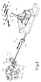
- FIG. 1 In the external shift actuation according to FIG. 1, 10 denotes a manual transmission flanged to a transverse internal combustion engine 11 for a passenger car.
- a shift stick 12 which is designed and stored in the usual way, is used for actuation.
- FIG. 1 also shows the usual shift pattern of a stick shift, in which the numbered arrows and the arrow labeled "R" indicate the shift direction for engaging the respective gear, while the selection direction is indicated by a double arrow 13 is indicated.
- a shift linkage is provided for transmitting the shifting and dialing forces manually applied to the shift stick 12, or the movements carried out by the shift stick 12, which are essentially made up of two connected by a joint 14 Shift rods 15, 16 there.
- the joint 14 must be able to transmit both the axial forces and movements (which arise during the switching process) and the torques and movements (associated with the selection movement) from the switching rod 15 to the second switching rod 16 which is at an obtuse angle.
- a second joint 17 which serves to transmit the forces and movements mentioned to a gear shift rod numbered 18.
- the requirements for the joint 17 correspond to those for the joint 14, so that the two joints 14, 17 can be designed essentially the same or similar. Possible embodiments for the joints 14, 17 are shown, for example, in FIGS. 16 to 23, which are described in detail below.
- the joint 17a also fulfills the same task as the joint 17 in the embodiment according to FIG. 1.
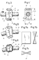
- 28, 29 denotes two articulated rods or shafts for connecting (in practice mostly pipes).
- an angle bent bracket 30 or 31 is welded.
- a band-shaped transmission member 32 made of thermoplastic material and designed as an injection-molded part, which serves to transmit torques and movements from shaft 28 to shaft 29 (or in the opposite direction).
- the band-shaped transmission member 32 has a relatively small thickness d and, in the untensioned state (FIG. 3), forms a vertical plane to the (common) axis 33, 34 of the two shafts 28, 29, the central axis of the band-shaped transmission member 32 being aligned with the two ( aligned) shaft axes 33, 34 covers.
- the band-shaped transmission member 32 is symmetrical, in such a way that it merges into an eyelet-shaped reinforcing element 35 at two opposite ends (in FIGS. 3 to 5 above and below).
- the eyelet-shaped reinforcing elements 35 are each pressed onto the horizontally bent ends of the arms 30, 31 (cf. in particular FIG. 4).
- the shaft 28 forms an angular deflection in the vertical direction with respect to the shaft 29.
- the angular deflection is made possible by appropriate flexible deformation of the band-shaped transmission member 32, but this still retains its ability to transmit torques to an almost unchanged extent.
- the shaft 28 again forms an angular deflection with respect to the shaft 29, but in this case in the horizontal direction (based on FIG. 3).
- This angular deflection is also made possible by corresponding flexible deformation of the band-shaped transmission member 32, as can be seen particularly well from FIGS. 7a to 7c.
- the deformation of the band-shaped transmission member 32 again does not impair, at least not significantly, its ability to transmit torques.
- the same also applies to a simultaneous superimposition of angular deflections of the type shown in FIGS. 5 and 6, as they occur constantly (in a periodically increasing and decreasing manner) with rotary movements of the two shafts 28, 29 which are at an angle to one another.
- FIGS. 8 and 9 now show a variant of a band-shaped transmission member 32a which is slightly modified compared to the embodiment according to FIGS. 3 to 6.
- the difference from the embodiment according to FIGS. 3 to 6 is that the eyelet-shaped reinforcing elements - here designated 35a - each have two openings 36, 37 lying next to one another.
- the cantilevers of the two shafts to be connected (not shown in FIGS. 8 and 9), which interact with the reinforcing elements 35a, should also be designed accordingly.
- FIGS. 10 and 11 show a further design option for a band-shaped transmission element.
- the band-shaped transmission element is designated 32b here and has two similar eyelet-shaped reinforcing elements 35b which are designed as rings in cross section.
- the reinforcement elements of the band-shaped transmission member 32c are double T-shaped. This results in two lateral recesses 38, 39, into which correspondingly complementary cantilever arms of the shafts to be connected (not shown) can engage from the side.
- a common feature of the embodiments according to FIGS. 3 to 6 and 8 to 13 is that the band-shaped transmission member 32 to 32c with its reinforcing elements 35 to 35c is formed in one piece.
- production as a plastic injection-molded part lends itself, the material advantageously being able to be reinforced by inlays made of fabric or wire.
- band-shaped transmission member 32d and reinforcing elements 35d are produced as separate parts.
- the reinforcing elements 35d can be made of a different material, e.g. B. a metal or an alloy, as the actual band-shaped transmission member 32d exist. This may be necessary if special claims, e.g. B. temperature behavior or strength.
- the reinforcement elements 35d can be attached to the ends of the actual band-shaped transmission member 32d by gluing, clamping or injecting. Riveting or screwing of the reinforcing elements 35d to the ends of the band-shaped transmission member 32d is also conceivable.
- FIGS. 16 and 17 show an embodiment of a complete joint which, in contrast to the embodiment according to FIGS. 3 to 6, is capable of transmitting not only torques but also axial forces at the same time.
- This joint can thus be used in shift linkages of the type shown in FIGS. 1 and 2.
- the two shafts to be connected are again designated 28 and 29 (as in FIGS. 3 to 6).
- a bracket 40 is welded onto the end of the shaft 28, which is angled several times and is asymmetrical.
- a bracket - numbered 41 - is welded on, but - as shown in FIG. 17 - only has the shape of a simple angle plate.
- the band-shaped transmission member 32e (designed similarly to the embodiment according to FIGS. 10 and 11) has two eyelet-shaped reinforcing elements 42 and 43 formed in one piece.
- the arm 40 grips on the (in FIG. 16 upper) reinforcing element 42 by means of a holder 44 on which a bolt 45 is welded on.
- a bolt 46 which engages in the eyelet-shaped reinforcing element 43, is correspondingly welded to the arm 41 (lower in FIG. 16).
- the (lower) reinforcing element 43 lying exactly between the two mutually facing shaft ends has on both sides two integrally formed, buffer-like buffer elements 47, 48.
- the buffer element 47 lies against the leg 49 of the U-shaped area of the arm 40, which is bent upwards, and the other buffer element 48 comes into contact with the opposite other U leg 50 of the arm 40.
- the axial forces are thus transmitted without play and - with a correspondingly rigid design of the buffer elements 47, 48 - also without damping from the shaft 29 initially to the (lower) reinforcing element 43. From there, the further transmission takes place by the bolt 46 via the arm 41 to the shaft 28.
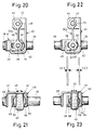
- the variant according to FIGS. 18 and 19 corresponds in most details to the embodiment according to FIGS. 16 and 17, which is why the relevant matching parts in question are provided with the same reference numerals as there for the sake of simplicity.
- the special feature of the embodiment according to FIGS. 18 and 19 is that a transmission of axial forces or movements only after bridging a play of 1/2 S (based on the central position of the band-shaped transmission element 32f shown in FIGS. 18 and 19) ) is possible.
- the (lower) reinforcing element designated here 51 - similar to the embodiment according to FIGS. 16 and 17 - has two laterally integrally formed spherical buffer elements 52, 53, which, in contrast to FIGS. 16 and 17, are not on the assigned surfaces 49 or 50 of the boom 40 but are located at an axial distance of 1/2 S to these surfaces. This results in the above-mentioned play in the transmission of axial forces and movements between the shafts 28, 29.
- the band-shaped transmission link is here designated 32g.
- the special feature of the embodiment according to FIGS. 20, 21 lies in the design of the lower reinforcing element, numbered 54.
- This has spherical buffer elements 55, 56 fastened on both sides, which, however, consist of a different material than the reinforcing element 54, namely an elastic, shock-absorbing material.
- the buffer elements 55, 56 can be plugged onto the reinforcing element 54, sprayed on or - if they are made of rubber - vulcanized on.
- the embodiment according to FIGS. 22 and 23 essentially corresponds to the embodiment according to FIGS. 18 and 19 described above.
- the matching parts are therefore provided with the same reference numerals as there.
- an axial play of 1/2 S each is provided in the transmission of axial forces between the shafts 28, 29.
- the characteristic of the embodiment according to FIGS. 22, 23 lies, however, in a combination of the special features by which the joint according to FIGS. 18, 19 on the one hand and the joint according to FIGS. 20, 21 on the other hand are distinguished.
- the band-shaped transmission member designated 32h has a lower reinforcing element 57, on which on both sides - similar to the embodiment according to FIGS.
- 60 denotes an actuating rod which is articulated via a band-shaped transmission member 61 to a bearing block 63 firmly clamped at 62.
- the band-shaped transmission member 61 with its upper reinforcing element 64 which (similar to the embodiment according to FIGS. 12 and 13) is double-T-shaped, is pressed into the bearing block 63, while the rod 60 axially secured in the lower reinforcing element 65 is rotatably mounted.
- the point P on the rod 60 should be able to carry out the deflections shown on a circle 66.
- a lever 67 attached to the rod 60 must be able to transmit forces in the direction of arrow 69 via a ball 68 when a torque is applied to the rod 60.
- the described transmission of forces, torques and movements is only possible because the band-shaped transmission member 61 is able to absorb the reaction forces over the cross section with its high section modulus.
Landscapes
- Engineering & Computer Science (AREA)
- General Engineering & Computer Science (AREA)
- Mechanical Engineering (AREA)
- Physics & Mathematics (AREA)
- General Physics & Mathematics (AREA)
- Automation & Control Theory (AREA)
- Gear-Shifting Mechanisms (AREA)
- Motor Power Transmission Devices (AREA)
- Vibration Prevention Devices (AREA)
Applications Claiming Priority (2)
| Application Number | Priority Date | Filing Date | Title |
|---|---|---|---|
| DE19873722033 DE3722033A1 (de) | 1987-07-03 | 1987-07-03 | Flexible gelenkverbindung zweier wellen, insbesondere fuer schaltgestaenge von kraftfahrzeuggetrieben |
| DE3722033 | 1987-07-03 |
Publications (3)
| Publication Number | Publication Date |
|---|---|
| EP0297359A2 EP0297359A2 (de) | 1989-01-04 |
| EP0297359A3 EP0297359A3 (en) | 1990-05-30 |
| EP0297359B1 true EP0297359B1 (de) | 1992-08-19 |
Family
ID=6330859
Family Applications (1)
| Application Number | Title | Priority Date | Filing Date |
|---|---|---|---|
| EP88109608A Expired - Lifetime EP0297359B1 (de) | 1987-07-03 | 1988-06-16 | Flexible Gelenkverbindung zweier Wellen, insbesondere für Schaltgestänge von Kraftfahrzeuggetrieben |
Country Status (3)
| Country | Link |
|---|---|
| EP (1) | EP0297359B1 (OSRAM) |
| DE (2) | DE3722033A1 (OSRAM) |
| ES (1) | ES2035161T3 (OSRAM) |
Families Citing this family (6)
| Publication number | Priority date | Publication date | Assignee | Title |
|---|---|---|---|---|
| DE3916569C1 (OSRAM) * | 1989-05-20 | 1990-08-09 | Ford-Werke Ag, 5000 Koeln, De | |
| DE10010804B4 (de) * | 2000-03-08 | 2004-09-16 | R&W Antriebselemente Gmbh | Gelenkverbindung, insbesondere zur Übertragung von Linearbewegungen |
| CN101737486B (zh) * | 2009-12-09 | 2012-09-05 | 上海惟译汽配制造有限公司 | 一种减少软轴承载峰值的汽车软轴变速操纵器 |
| ES2555403T3 (es) * | 2011-08-08 | 2015-12-30 | Centa-Antriebe Kirschey Gmbh | Unidad de acoplamiento para conectar un accionamiento a un eje de salida |
| US11047419B2 (en) | 2017-02-20 | 2021-06-29 | Keith Boutte | Segmented driveshaft |
| CN107725754B (zh) * | 2017-11-22 | 2023-09-19 | 东风华神汽车有限公司 | 一种机械式单杆变速箱选换挡操纵机构 |
Family Cites Families (14)
| Publication number | Priority date | Publication date | Assignee | Title |
|---|---|---|---|---|
| DE300336C (OSRAM) * | ||||
| DE411559C (de) * | 1925-04-01 | Alpe Patent Coupling Co Ltd | Nachgiebige, scheibenfoermige Kupplung fuer Kraftfahrzeuge | |
| GB191411166A (en) * | 1914-05-06 | 1915-05-06 | Ed J Hardy And Company Ltd | Improvements in Universal Joints. |
| GB517635A (en) * | 1937-07-31 | 1940-02-05 | Marconi Wireless Telegraph Co | Improvements in or relating to flexible couplings for shafts |
| FR933252A (fr) * | 1945-10-17 | 1948-04-15 | Gen Tire & Rubber Co | Accouplement élastique |
| US2855767A (en) * | 1952-03-20 | 1958-10-14 | Svenska Rotor Maskiner Ab | Yieldable coupling |
| US2903867A (en) * | 1956-02-17 | 1959-09-15 | Lear Inc | Zero-backlash coupling for shafts or the like |
| GB861600A (en) * | 1957-06-18 | 1961-02-22 | Sperry Gyroscope Co Ltd | Flexible coupling |
| US3224224A (en) * | 1963-06-07 | 1965-12-21 | Acushnet Process Company | Flexible coupling |
| DE1931577B2 (de) * | 1969-06-21 | 1971-06-24 | Verfahren zum herstellen einer elastischen mitnehmerscheibe mit eingelagertem stuetzgewebe | |
| IT944999B (it) * | 1970-12-28 | 1973-04-20 | North American Rockwell | Complesso di piantone di guida deformabile |
| CS149000B1 (OSRAM) * | 1971-01-22 | 1973-05-24 | ||
| US3935716A (en) * | 1972-05-11 | 1976-02-03 | Kupplungstechnik Gmbh | Shaft coupling |
| DE2834070A1 (de) * | 1978-08-03 | 1980-02-14 | Volkswagenwerk Ag | Vorrichtung zur starren, umfangsspielfreien, aber axial nachgiebigen wellenverbindung |
-
1987
- 1987-07-03 DE DE19873722033 patent/DE3722033A1/de active Granted
-
1988
- 1988-06-16 EP EP88109608A patent/EP0297359B1/de not_active Expired - Lifetime
- 1988-06-16 ES ES198888109608T patent/ES2035161T3/es not_active Expired - Lifetime
- 1988-06-16 DE DE8888109608T patent/DE3873841D1/de not_active Expired - Lifetime
Also Published As
| Publication number | Publication date |
|---|---|
| DE3722033C2 (OSRAM) | 1989-04-27 |
| ES2035161T3 (es) | 1993-04-16 |
| EP0297359A2 (de) | 1989-01-04 |
| DE3873841D1 (de) | 1992-09-24 |
| EP0297359A3 (en) | 1990-05-30 |
| DE3722033A1 (de) | 1989-01-12 |
Similar Documents
| Publication | Publication Date | Title |
|---|---|---|
| EP1482213B1 (de) | Betätigungseinrichtung für ein Schaltgetriebe | |
| DE3320760A1 (de) | Antriebswelle | |
| DE3307950C2 (de) | Schalthebel für ein handschaltbares Getriebe | |
| DE4100574A1 (de) | Gelenk zwischen einem getriebe und dessen gang-schaltmechanismus mit fernbetaetigung | |
| DE3808025A1 (de) | Schalthebel | |
| EP0297359B1 (de) | Flexible Gelenkverbindung zweier Wellen, insbesondere für Schaltgestänge von Kraftfahrzeuggetrieben | |
| EP0563940A2 (de) | Elastisches Kreuzgelenk | |
| EP0442082B1 (de) | Verbindungseinrichtung für des Schaltgestänge von Kraftfahrzeugen | |
| DE19538424C2 (de) | Wischervorrichtung für ein Fahrzeug | |
| EP2014957B1 (de) | Betätigungsvorrichtung für ein Schaltgetriebe eines Kraftfahrzeuges | |
| EP0399106B1 (de) | Getriebeschaltstange mit Schwingungsdämpfer | |
| DE2318629B2 (de) | Zentriervorrichtung für eine drehelastische Wellenkupplung | |
| DE3634174A1 (de) | Vorrichtung zum daempfen von schwingungen in einer getriebeschaltvorrichtung fuer fahrzeuge | |
| EP0010594B1 (de) | Drehelastische Kupplung, insbesondere Lenksäulenkupplung für Kraftfahrzeuge | |
| EP0674124B1 (de) | Gelenk zwischen einem Getriebebetätigungsglied und einer Getriebegangschaltvorrichtung | |
| DE10033592A1 (de) | Schalthebel-Lageranordnung | |
| DE3109182C1 (de) | Verbindungselement für Schaltgestänge von Kraftfahrzeugen | |
| DE3101671A1 (de) | Elastische gestaengekupplung, insbesondere fuer schaltgestaenge an kraftfahrzeugen | |
| DE69200236T2 (de) | Mechanische Übertragung zwischen einem Schalthebel und dem Getriebe. | |
| DE19540897C1 (de) | Vorrichtung zum Schalten von Kraftfahrzeug-Wechselgetrieben | |
| EP0123105B1 (de) | Entkopplungsvorrichtung für Schaltgestänge | |
| DE19901074C2 (de) | Schaltstangenkupplung | |
| DE102020101862B3 (de) | Hebelaktor mit einem Segmentgelenk | |
| EP1147038A1 (de) | Wischergestänge einer scheibenwischanlage für fahrzeuge und verfahren zu dessen herstellung | |
| DE4001145A1 (de) | Elastische kupplung fuer die verbindung von wellenteilen eines antriebsstrangs eines kraftfahrzeugs |
Legal Events
| Date | Code | Title | Description |
|---|---|---|---|
| PUAI | Public reference made under article 153(3) epc to a published international application that has entered the european phase |
Free format text: ORIGINAL CODE: 0009012 |
|
| AK | Designated contracting states |
Kind code of ref document: A2 Designated state(s): DE ES FR GB IT NL |
|
| PUAL | Search report despatched |
Free format text: ORIGINAL CODE: 0009013 |
|
| AK | Designated contracting states |
Kind code of ref document: A3 Designated state(s): DE ES FR GB IT NL |
|
| 17P | Request for examination filed |
Effective date: 19900905 |
|
| 17Q | First examination report despatched |
Effective date: 19911119 |
|
| GRAA | (expected) grant |
Free format text: ORIGINAL CODE: 0009210 |
|
| AK | Designated contracting states |
Kind code of ref document: B1 Designated state(s): DE ES FR GB IT NL |
|
| ET | Fr: translation filed | ||
| ITF | It: translation for a ep patent filed | ||
| GBT | Gb: translation of ep patent filed (gb section 77(6)(a)/1977) | ||
| REF | Corresponds to: |
Ref document number: 3873841 Country of ref document: DE Date of ref document: 19920924 |
|
| REG | Reference to a national code |
Ref country code: ES Ref legal event code: FG2A Ref document number: 2035161 Country of ref document: ES Kind code of ref document: T3 |
|
| PLBE | No opposition filed within time limit |
Free format text: ORIGINAL CODE: 0009261 |
|
| STAA | Information on the status of an ep patent application or granted ep patent |
Free format text: STATUS: NO OPPOSITION FILED WITHIN TIME LIMIT |
|
| ITTA | It: last paid annual fee | ||
| 26N | No opposition filed | ||
| PGFP | Annual fee paid to national office [announced via postgrant information from national office to epo] |
Ref country code: NL Payment date: 20000630 Year of fee payment: 13 |
|
| REG | Reference to a national code |
Ref country code: GB Ref legal event code: 746 Effective date: 20010220 |
|
| PGFP | Annual fee paid to national office [announced via postgrant information from national office to epo] |
Ref country code: GB Payment date: 20010601 Year of fee payment: 14 |
|
| REG | Reference to a national code |
Ref country code: FR Ref legal event code: D6 |
|
| PGFP | Annual fee paid to national office [announced via postgrant information from national office to epo] |
Ref country code: ES Payment date: 20010612 Year of fee payment: 14 |
|
| PGFP | Annual fee paid to national office [announced via postgrant information from national office to epo] |
Ref country code: FR Payment date: 20010621 Year of fee payment: 14 |
|
| PGFP | Annual fee paid to national office [announced via postgrant information from national office to epo] |
Ref country code: DE Payment date: 20010824 Year of fee payment: 14 |
|
| PG25 | Lapsed in a contracting state [announced via postgrant information from national office to epo] |
Ref country code: NL Free format text: LAPSE BECAUSE OF NON-PAYMENT OF DUE FEES Effective date: 20020101 |
|
| REG | Reference to a national code |
Ref country code: GB Ref legal event code: IF02 |
|
| NLV4 | Nl: lapsed or anulled due to non-payment of the annual fee |
Effective date: 20020101 |
|
| PG25 | Lapsed in a contracting state [announced via postgrant information from national office to epo] |
Ref country code: GB Free format text: LAPSE BECAUSE OF NON-PAYMENT OF DUE FEES Effective date: 20020616 |
|
| PG25 | Lapsed in a contracting state [announced via postgrant information from national office to epo] |
Ref country code: ES Free format text: LAPSE BECAUSE OF NON-PAYMENT OF DUE FEES Effective date: 20020617 |
|
| PG25 | Lapsed in a contracting state [announced via postgrant information from national office to epo] |
Ref country code: DE Free format text: LAPSE BECAUSE OF NON-PAYMENT OF DUE FEES Effective date: 20030101 |
|
| GBPC | Gb: european patent ceased through non-payment of renewal fee |
Effective date: 20020616 |
|
| PG25 | Lapsed in a contracting state [announced via postgrant information from national office to epo] |
Ref country code: FR Free format text: LAPSE BECAUSE OF NON-PAYMENT OF DUE FEES Effective date: 20030228 |
|
| REG | Reference to a national code |
Ref country code: FR Ref legal event code: ST |
|
| REG | Reference to a national code |
Ref country code: ES Ref legal event code: FD2A Effective date: 20030711 |
|
| PG25 | Lapsed in a contracting state [announced via postgrant information from national office to epo] |
Ref country code: IT Free format text: LAPSE BECAUSE OF NON-PAYMENT OF DUE FEES;WARNING: LAPSES OF ITALIAN PATENTS WITH EFFECTIVE DATE BEFORE 2007 MAY HAVE OCCURRED AT ANY TIME BEFORE 2007. THE CORRECT EFFECTIVE DATE MAY BE DIFFERENT FROM THE ONE RECORDED. Effective date: 20050616 |