EP0296397A1 - Treibkeilriemen - Google Patents
Treibkeilriemen Download PDFInfo
- Publication number
- EP0296397A1 EP0296397A1 EP88108943A EP88108943A EP0296397A1 EP 0296397 A1 EP0296397 A1 EP 0296397A1 EP 88108943 A EP88108943 A EP 88108943A EP 88108943 A EP88108943 A EP 88108943A EP 0296397 A1 EP0296397 A1 EP 0296397A1
- Authority
- EP
- European Patent Office
- Prior art keywords
- semi
- shaped metal
- cylindrical
- power transmitting
- belt
- Prior art date
- Legal status (The legal status is an assumption and is not a legal conclusion. Google has not performed a legal analysis and makes no representation as to the accuracy of the status listed.)
- Granted
Links
Images
Classifications
-
- F—MECHANICAL ENGINEERING; LIGHTING; HEATING; WEAPONS; BLASTING
- F16—ENGINEERING ELEMENTS AND UNITS; GENERAL MEASURES FOR PRODUCING AND MAINTAINING EFFECTIVE FUNCTIONING OF MACHINES OR INSTALLATIONS; THERMAL INSULATION IN GENERAL
- F16G—BELTS, CABLES, OR ROPES, PREDOMINANTLY USED FOR DRIVING PURPOSES; CHAINS; FITTINGS PREDOMINANTLY USED THEREFOR
- F16G5/00—V-belts, i.e. belts of tapered cross-section
- F16G5/16—V-belts, i.e. belts of tapered cross-section consisting of several parts
Definitions
- the present invention relates to a power transmitting V-belt and, more particularly, to a power transmitting V-belt for use in combination with a variable diameter V-pulley.
- V-belts for use in V-belt type continuously variable transmissions for vehicles that employ variable diameter V-pulleys.
- V-belts normally are comprised of a metal band which is formed of a plurality of endless laminated metal band elements and which are restrained and held by a large number of V-shaped metal blocks provided adjacent one another.
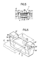
- Fig. 6 illustrates a perspective view of a V-shaped metal block in a V-belt of this type disclosed in Japanese Utility Model Application Laid-Open No. 79038/85 assigned to the assignee of this application.
- the prior art V-shaped metal block 4′ shown in Fig. 6 has a recessed groove 5′ that is open upwardly with a bottom surface of the recessed groove 5′ being formed as a support surface 5a′ bearing against a lower surface of a metal band B′, shown by one-dash chain line, to support the band.
- the metal block 4′ is also provided, at its opposite side surfaces, as viewed in a lengthwise direction of the metal band B′, with widthwise extending semi-cylindrical recesses 8′.
- a roller member is interposed between the opposed recesses 8′ of the adjacent metal blocks to provide an assembled V-belt.
- one of the two recesses 8′ on the metal block 4′ may be replaced by a semi-cylindrical projection which is directly engaged in the semi-cylindrical recess of the adjacent metal block.
- the V-shaped metal block 4′ has a pair of inclined portions 4a′, 4a′ formed at its opposite ends, as viewed in the widthwise direction of the band B′ that are adapted to engage a V-groove of a V-pulley which is not shown.
- the block 4' has an upper wall 4b′, a transverse groove 9a′extending in a lengthwise direction of the band, and a vertical groove 9b′ extending in the direction of the thickness of the band for receiving a wire stopper member 6′, indicated by one-dash chain line, which is locked at its opposite ends, so that the metal band B′ placed on the support surface 5a′ is restrained and held on the support surface 5a′ by the stopper member 6′.
- the transverse and vertical grooves 9a′ and 9b′ form a curved slot 9′ for locking the stopper member.
- the above construction provides an advantage that the height of the upper wall 4b′,i.e., the entire height of the metal block itself, can be reduced but the following problems still remain unsolved. More specifically, in producing the metal bock of such a complicated shape, for example from a sintered alloy, the semi-cylindrical recesses 8′ located on the front and rear opposite side surfaces are shaped using complementary convex dies and hence the central portion of each of the recesses 8′ of the metal block 4′ tends to have a high density of material. For this reason, a phenomenon of expansion of the central portion may be produced in the course of sintering and thermal treatment steps.
- roller member when the roller member is interposed between the respective proposed recesses 8′ of the two adjacent V-shaped metal blocks, the roller member bears only against the central portions of the recesses 8′ and is not in uniform contact with the recessed over the entire axial region thereof.
- roller member since the roller member is relatively long, it is difficult to obtain uniform lubrication of the roller member along its entire length.
- a relief portion having a suitable length is concavely formed at an axially central portion of each of semi-cylindrical recesses defined on each of metal blocks of a V-belt and is recessed more deeply than the remainder of the recesses.
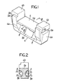
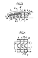
- a metal band B is comprised of a plurality of endless laminated metal band elements Ba and has a bottom surface bearing on a support surface 5a which forms a bottom surface of an upwardly opened recessed groove 5 for receiving the metal band B in each of a large number of V-shaped metal blocks 4.
- a wire stopper member 6 is locked at its opposite ends in a transverse groove 9a and a vertical groove 9b of a locking slot 9 to restrain and hold the metal band B.
- a roller member 7 is interposed between opposed semi-cylindrical recesses 8 provided on the opposite side surfaces, as viewed in the lengthwise direction of the band B, of adjacent V-shaped metal blocks 4.
- the roller member 7 may be cylindrical or at least provided with a pair of oppositely facing semi-cylindrical projections engaging the semi-cylindrical recesses.
- a V-belt 1 of this embodiment is comprised of the metal band B, a large number of the V-shaped metal blocks 4, a large number of the roller members 7 and a large number of the stopper members 6.
- the V-shaped metal block 4 is similar in basic structure to the prior art V-shaped metal block shown in Fig. 6 and has the recessed groove 5 between the opposite upper walls 4b, 4b thereof and a pair of inclined portions 4a, 4a formed at its opposite side surfaces, as viewed in the widthwise direction of the band B adapted to engage a V-groove of a V-pulley 10.
- a semi-cylindrical recess or relief portion 8a having a certain axial width is provided at an axially central portion of each of the semi-cylindrical recesses 8 of each of the V-shaped metal blocks 4.
- the relief portion has a radius R2 slightly larger than the radius R1 of the recess 8 (see Figs. 1 and 2). Therefore, the relief portion 8a is formed on the metal block 4 to be recessed more deeply than the recess 8.
- the provision of the suitable relief portion 8a at the central portion of each of the pair of recesses 8 in the V-shaped metal block 4 makes it possible to compensate for any expansion of the metal at the central portion during sintering and thermal treatment due to the densification of the material when such metal block 4 is formed, for example, from a sintered alloy using complemental convex dies. Moreover, it is possible to prevent the generation of high surface pressure at the central portion due to an uneven contact with the roller member 7 and seizure due to failure of lubrication during use of the V-belt.
- This construction permits the use of, for example, an iron-based sintered alloy as a material for such a block of a complicated shape which avoids the costly conventional machining otherwise required.
- a sintered product previously impregnated with a lubricant in a so-called oilless (oil impregnated) bearing manner utilizing a porous structure, which is a characteristic thereof, can considerably improve the lubricity to reduce the frictional force and further contribute to prevention of a seizure or the like.
Landscapes
- Engineering & Computer Science (AREA)
- General Engineering & Computer Science (AREA)
- Mechanical Engineering (AREA)
- Powder Metallurgy (AREA)
- Pulleys (AREA)
- Transmissions By Endless Flexible Members (AREA)
Applications Claiming Priority (2)
| Application Number | Priority Date | Filing Date | Title |
|---|---|---|---|
| JP86771/87 | 1987-06-05 | ||
| JP1987086771U JPS63195143U (de) | 1987-06-05 | 1987-06-05 |
Publications (2)
| Publication Number | Publication Date |
|---|---|
| EP0296397A1 true EP0296397A1 (de) | 1988-12-28 |
| EP0296397B1 EP0296397B1 (de) | 1991-08-14 |
Family
ID=13896013
Family Applications (1)
| Application Number | Title | Priority Date | Filing Date |
|---|---|---|---|
| EP88108943A Expired EP0296397B1 (de) | 1987-06-05 | 1988-06-03 | Treibkeilriemen |
Country Status (4)
| Country | Link |
|---|---|
| US (1) | US4854926A (de) |
| EP (1) | EP0296397B1 (de) |
| JP (1) | JPS63195143U (de) |
| DE (1) | DE3864205D1 (de) |
Families Citing this family (9)
| Publication number | Priority date | Publication date | Assignee | Title |
|---|---|---|---|---|
| CA2047048C (en) * | 1990-07-25 | 1996-07-30 | Takashi Masuda | High load force transmission belt |
| JPH0738749Y2 (ja) * | 1991-04-25 | 1995-09-06 | 有限会社マツオエンジニアリング | 無段変速用駆動ベルト |
| EP1061285B1 (de) * | 1999-06-18 | 2003-10-08 | Honda Giken Kogyo Kabushiki Kaisha | Riemen für stufenlos regelbares Getriebe |
| WO2012164639A1 (ja) * | 2011-05-27 | 2012-12-06 | トヨタ自動車株式会社 | 伝動ベルトおよび伝動ベルトの組付方法 |
| JP5840293B2 (ja) * | 2012-07-06 | 2016-01-06 | 本田技研工業株式会社 | 金属ベルト用エレメント |
| WO2017200057A1 (ja) * | 2016-05-18 | 2017-11-23 | アイシン・エィ・ダブリュ株式会社 | 伝達ベルト |
| WO2018159858A1 (ja) * | 2017-03-03 | 2018-09-07 | アイシン・エィ・ダブリュ株式会社 | エレメントの設計方法および伝動ベルト |
| JP6809368B2 (ja) * | 2017-05-16 | 2021-01-06 | アイシン・エィ・ダブリュ株式会社 | 無段変速機および伝動ベルト |
| JP6621495B2 (ja) * | 2018-04-03 | 2019-12-18 | 本田技研工業株式会社 | 無段変速機用金属エレメントおよび無段変速機用金属エレメントの製造方法 |
Citations (1)
| Publication number | Priority date | Publication date | Assignee | Title |
|---|---|---|---|---|
| US4552548A (en) * | 1983-11-07 | 1985-11-12 | Honda Giken Kogyo Kabushiki Kaisha | V-Belt transmission apparatus |
Family Cites Families (3)
| Publication number | Priority date | Publication date | Assignee | Title |
|---|---|---|---|---|
| JPS61266844A (ja) * | 1985-05-18 | 1986-11-26 | Honda Motor Co Ltd | トルク伝導装置用積層金属ベルト |
| US4741727A (en) * | 1985-12-23 | 1988-05-03 | Honda Giken Kogyo Kabushiki Kaisha | Power transmission V belt |
| US4758211A (en) * | 1985-12-25 | 1988-07-19 | Honda Giken Kogyo Kabushiki Kaisha | V belt for power transmission |
-
1987
- 1987-06-05 JP JP1987086771U patent/JPS63195143U/ja active Pending
-
1988
- 1988-06-03 DE DE8888108943T patent/DE3864205D1/de not_active Expired - Lifetime
- 1988-06-03 EP EP88108943A patent/EP0296397B1/de not_active Expired
- 1988-06-06 US US07/203,001 patent/US4854926A/en not_active Expired - Fee Related
Patent Citations (1)
| Publication number | Priority date | Publication date | Assignee | Title |
|---|---|---|---|---|
| US4552548A (en) * | 1983-11-07 | 1985-11-12 | Honda Giken Kogyo Kabushiki Kaisha | V-Belt transmission apparatus |
Non-Patent Citations (1)
| Title |
|---|
| PATENT ABSTRACTS OF JAPAN, vol. 7, no. 177 (M-233)[1322], 5th August 1983; & JP-A-58 81 252 (NISSAN JIDOSHA K.K.) 16-05-1983 * |
Also Published As
| Publication number | Publication date |
|---|---|
| JPS63195143U (de) | 1988-12-15 |
| DE3864205D1 (de) | 1991-09-19 |
| US4854926A (en) | 1989-08-08 |
| EP0296397B1 (de) | 1991-08-14 |
Similar Documents
| Publication | Publication Date | Title |
|---|---|---|
| AU641260B2 (en) | High load force transmission belt | |
| US4854926A (en) | Power Transmitting V-belt | |
| EP0125751B1 (de) | Kettenband | |
| US4498892A (en) | Power transmission belt | |
| EP1132649B1 (de) | Element von metallriemen | |
| US4500305A (en) | Side-bar chain for infinitely variable cone pulley transmissions | |
| EP0060008A1 (de) | Transmissionskette | |
| US4650444A (en) | Endless transmission belt | |
| JPS6317879Y2 (de) | ||
| US5094548A (en) | Composite and self-lubricating bushing | |
| US4737137A (en) | Endless transmission belt | |
| EP1371876B1 (de) | Riemen für ein stufenlos regelbares Getriebe | |
| EP2236857B1 (de) | Metallisches Druckband und entsprechende Ölspezifikation | |
| US4741727A (en) | Power transmission V belt | |
| US6540404B1 (en) | Sintered plain bearing for engines and gears | |
| US4891039A (en) | Power transmitting V-belt | |
| GB2112494A (en) | Link plate chain for loop-type transmissions | |
| US4986798A (en) | Transmission chain with pivot pins and intermediate pieces with rolling contact action | |
| US6688001B2 (en) | Method and apparatus of working plain bearing | |
| US5788594A (en) | Low noise belt for continuously variable transmission | |
| US4900296A (en) | Articulated belt for continuously variable conical pulley, belt-drive transmission | |
| GB2040367A (en) | Improvements in the physical characteristics of a pair of sliding elements | |
| EP0510990B1 (de) | Treibriemen für ein stufenlos regelbares Getriebe | |
| US5374223A (en) | Transverse element for an endless transmission unit | |
| JPS638330B2 (de) |
Legal Events
| Date | Code | Title | Description |
|---|---|---|---|
| PUAI | Public reference made under article 153(3) epc to a published international application that has entered the european phase |
Free format text: ORIGINAL CODE: 0009012 |
|
| AK | Designated contracting states |
Kind code of ref document: A1 Designated state(s): DE FR GB IT |
|
| 17P | Request for examination filed |
Effective date: 19890110 |
|
| 17Q | First examination report despatched |
Effective date: 19891218 |
|
| GRAA | (expected) grant |
Free format text: ORIGINAL CODE: 0009210 |
|
| AK | Designated contracting states |
Kind code of ref document: B1 Designated state(s): DE FR GB IT |
|
| PG25 | Lapsed in a contracting state [announced via postgrant information from national office to epo] |
Ref country code: IT Free format text: LAPSE BECAUSE OF FAILURE TO SUBMIT A TRANSLATION OF THE DESCRIPTION OR TO PAY THE FEE WITHIN THE PRE;WARNING: LAPSES OF ITALIAN PATENTS WITH EFFECTIVE DATE BEFORE 2007 MAY HAVE OCCURRED AT ANY TIME BEFORE 2007. THE CORRECT EFFECTIVE DATE MAY BE DIFFERENT FROM THE ONE RECORDED.SCRIBED TIME-LIMIT Effective date: 19910814 Ref country code: FR Effective date: 19910814 |
|
| REF | Corresponds to: |
Ref document number: 3864205 Country of ref document: DE Date of ref document: 19910919 |
|
| EN | Fr: translation not filed | ||
| PG25 | Lapsed in a contracting state [announced via postgrant information from national office to epo] |
Ref country code: GB Effective date: 19920603 |
|
| PLBE | No opposition filed within time limit |
Free format text: ORIGINAL CODE: 0009261 |
|
| STAA | Information on the status of an ep patent application or granted ep patent |
Free format text: STATUS: NO OPPOSITION FILED WITHIN TIME LIMIT |
|
| 26N | No opposition filed | ||
| GBPC | Gb: european patent ceased through non-payment of renewal fee |
Effective date: 19920603 |
|
| PGFP | Annual fee paid to national office [announced via postgrant information from national office to epo] |
Ref country code: DE Payment date: 19940630 Year of fee payment: 7 |
|
| PG25 | Lapsed in a contracting state [announced via postgrant information from national office to epo] |
Ref country code: DE Effective date: 19960301 |