EP0296164B1 - Coin assorting device - Google Patents
Coin assorting device Download PDFInfo
- Publication number
- EP0296164B1 EP0296164B1 EP87901736A EP87901736A EP0296164B1 EP 0296164 B1 EP0296164 B1 EP 0296164B1 EP 87901736 A EP87901736 A EP 87901736A EP 87901736 A EP87901736 A EP 87901736A EP 0296164 B1 EP0296164 B1 EP 0296164B1
- Authority
- EP
- European Patent Office
- Prior art keywords
- coin
- coins
- bottom plate
- thickness
- disc
- Prior art date
- Legal status (The legal status is an assumption and is not a legal conclusion. Google has not performed a legal analysis and makes no representation as to the accuracy of the status listed.)
- Expired
Links
Images
Classifications
-
- G—PHYSICS
- G07—CHECKING-DEVICES
- G07D—HANDLING OF COINS OR VALUABLE PAPERS, e.g. TESTING, SORTING BY DENOMINATIONS, COUNTING, DISPENSING, CHANGING OR DEPOSITING
- G07D3/00—Sorting a mixed bulk of coins into denominations
-
- G—PHYSICS
- G07—CHECKING-DEVICES
- G07D—HANDLING OF COINS OR VALUABLE PAPERS, e.g. TESTING, SORTING BY DENOMINATIONS, COUNTING, DISPENSING, CHANGING OR DEPOSITING
- G07D1/00—Coin dispensers
Definitions
- the invention relates to a coin assorting device comprising a disc mounted for rotation on a bottom plate to pass, when rotating, below a coin supply tube for coins stacked therein, said disk forming two pains of recesses diametrically opposite each other in each pair, for receiving a coin from the coin supply tube in each recess, said bottom plate having a discharge opening for coins the diameter of which is less than a predetermined maximum diameter of the coins supplied.
- Coin assorting means of this type are used in coin assorting machines for a so called second sorting of the coins. Then, the coins of an unassorted coin body are first subject to a first sortening, wherein the coins one after the other are allowed to roll along a sloping path and in dependence of the size of the coin diameter are diverted therefrom in one of a number of stations, where the coins are allowed to fall into coin tubes, the inside diameter of which is adjusted to the diameter of the coins to be received therein. In the coin tube the coins will form a pile which accordingly should include only coins of one and the same diameter.
- FR 761 390 discloses a coin selector for supplying coins to a game apparatus.
- the coins are introduced into the coin selector by displacement one by one of a coin on a bottom plate in the radial direction towards a rotatable disk provided with recesses, said disk being rotatable on a bottom plate with discharge openings.
- a main object of the present invention thus is to reduce, in coin assorting devices of the kind mentioned initially, the risk that interruption in the operation caused by cramping should happen.
- still another object of the invention is to remove this interruption of the operation by automatically during a short sequence reversing the rotational movement of the rotatable disc and by striking action against the coin eliminate the cramping and then automatically revert to the initial rotational direction at the same time discharging coins.
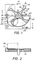
- the coin assorting device comprises a bottom plate 10, which should be fixedly mounted in a coin assorting machine.
- This bottom plate has on the upper side thereof a milled recess 11, with a flat bottom in which a disc 12 is rotatably mounted by means of a drive shaft 13.
- the rotatable disc 12 has four wings 14 which project from a hub 15 and are separated from each other by means of substantially semicircular recesses 16.
- the intended rotational direction of the disc is indicated by an arrow 17, and the edges of the recesses 16 are provided with a chamfer 18, so that each wing 14 is chamfered on the front edge thereof, as seen in the rotational direction, as well as on the opposite edge.
- a coin tube 19 connects to the upper side of the disc 12 rotatable in the bottom plate 10, said tube being arranged to receive coins from a device for a first sortening.
- the disc 12 should preferably have a maximum thickness which equals the thickness of the coins to be received by the coin tube 19, such that the disc when rotating past the lower end of the coin tube 19 will bring along the coin which at each occasion is the lowermost coin of a coin pile in the coin tube, when a recess 16 passes the coin tube 19.
- the chamfer 18 on the front and rear edges of the wings 14 is shaped to form a blunt edge, said blunt edge preferably having a height which substantially corresponds to the thickness of the smallest coin.
- a discharge opening 20 which is defined by two circular edges 21 and 22, the center of which is located on the rotational axis of the disc 12. These two edges are radially spaced from each other a distance which is somewhat less than the diameter of the coins to be received by the coin tube 19, such that these coins resting on narrow portions at each of the edges 21 and 22 can pass the discharge opening 20 when they are brought along by the rotatable disc 12, then to be supplied to a suitable collection means for these coins at an edge 23 of the bottom plate.
- a coin, if any, having less diameter than the intended diameter of the coins in the coin pile received by the coin tube 19, will be discharged, however, by falling down through the opening 20 in order to be collected at another location.
- the opening 20 in the bottom plate 10 extends beneath the mouth of the coin tube 19.
- the dimensions of the portion of the opening 20 which extends beneath the lower end of the coin tube 19 are preferable such that the distance between opposite limiting borders of the opening 20 does not coincide with the diameter of any known coin which might be present in the coin tube.
- the major portion of the limiting border of the opening 20 which extends beneath the coin tube is further provided with a chamfer 24, which further facilitates for incorrect coins to fall down into the through opening 20 at an early stage.
- Fig 3 schematically illustrates an arrangement for automatically, when cramping between two coins and the lower edge of the coin tube has occurred, induce a reversed rotational direction of the rotatable disc during a short sequence corresponding to half a revolution, in order to loosen the cramping grip of the coins, and then immediately bring the rotatable disc to rotate in the initial rotational direction at the same time dischaging coins.
- a transmission sheave 25 for a transmission belt, e.g. an O-ring 26, is mounted on the downwardly projecting portion of the drive shaft 13 of the rotatable disc 12.
- a shaft 27 which also is provided with a corresponding transmission sheave 25, is rotatably mounted in bearings in parallel with the drive shaft 11.
- Said two transmission sheaves 25 form together with the O-ring 26 a transmission for driving the shaft 27 for rotation synchronously with the drive shaft 13.
- Supported by shaft 27 is also a thin disc 28 provided with a periferal through opening 29.
- Mounted close to the disc 28 is an optical fork-shaped sensor 30, the branches of said fork being disposed one above and the other beneath the disc 28.
- One of the branches of the fork is provided with means for emitting a light beam vertically through the opening 29, and the opposite branch of the fork is provided with means for registering said light beam.
- the optical sensor 30 is adapted to trigger a control signal to the drive motor for said disc 12 for reversing the rotational direction during a predetermined period which approximately corresponds to half a revolution, and then again to reverse the rotational direction back to normal direction.
- the rotatable disc 12 is thus made to rotate in the opposite direction, the rear edge of the wing 14 then by striking action against the coin drives the coin back thus changing the relative positions of the coins so that when the rotatable disc again starts to rotate in its normal rotational direction, the wing 14 manages to discharge the lowermost coin.
- a pin 31 is fixed to the bottom plate, said pin limiting the backwards movement of the coin.
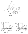
- Figures 4 and 5 illustrate two different situations involving a certain risk of cramping of coins against the lower edge of the coin tube 19.
- Fig 4 illustrates a case in which an incorrectly sorted small coin 32 has landed on the feeding plate 10 beneath a correct coin 33.
- this situation does not lead to any major problem since the chamfered front edge of the wing 14 when said wing rotates only brings along the small coin 32, which after forwarding falls down through the opening 20, after which the following wing 14 brings along the coin 33. It may happen, however, that both coins 32 and 33 are displaced in direction forwards and then are cramped below the coin tube 19.
- the rotatable disc is made to reverse in the manner described above, resulting in that the rear chamfered edge of the wing 14 strikes against the front edge of the coin 33 thereby displacing said coin in the rearward direction so that the relative position between coins 32 and 33 is changed.
- the following feeding action by means of wing 14 only coin 32 is fed to the opening 20, the following wing 14 then discharging the correct coin 33.
Landscapes
- Physics & Mathematics (AREA)
- General Physics & Mathematics (AREA)
- Testing Of Coins (AREA)
- Control Of Vending Devices And Auxiliary Devices For Vending Devices (AREA)
- Iron Core Of Rotating Electric Machines (AREA)
- Sorting Of Articles (AREA)
- Feeding Of Articles To Conveyors (AREA)
- Attitude Control For Articles On Conveyors (AREA)
- Color Television Image Signal Generators (AREA)
- Lubrication Of Internal Combustion Engines (AREA)
- Color Image Communication Systems (AREA)
- Preparation Of Compounds By Using Micro-Organisms (AREA)
- Saccharide Compounds (AREA)
- Pharmaceuticals Containing Other Organic And Inorganic Compounds (AREA)
Priority Applications (1)
| Application Number | Priority Date | Filing Date | Title |
|---|---|---|---|
| AT87901736T ATE72069T1 (de) | 1986-03-11 | 1987-03-04 | Muenzensortiervorrichtung. |
Applications Claiming Priority (2)
| Application Number | Priority Date | Filing Date | Title |
|---|---|---|---|
| SE8601117A SE457998B (sv) | 1986-03-11 | 1986-03-11 | Myntsorteringsanordning |
| SE8601117 | 1986-03-11 |
Publications (2)
| Publication Number | Publication Date |
|---|---|
| EP0296164A1 EP0296164A1 (en) | 1988-12-28 |
| EP0296164B1 true EP0296164B1 (en) | 1992-01-22 |
Family
ID=20363772
Family Applications (1)
| Application Number | Title | Priority Date | Filing Date |
|---|---|---|---|
| EP87901736A Expired EP0296164B1 (en) | 1986-03-11 | 1987-03-04 | Coin assorting device |
Country Status (9)
| Country | Link |
|---|---|
| US (2) | US4943257A (da) |
| EP (1) | EP0296164B1 (da) |
| JP (1) | JPS63502859A (da) |
| AT (1) | ATE72069T1 (da) |
| DE (1) | DE3776335D1 (da) |
| DK (1) | DK165607C (da) |
| NO (1) | NO168331C (da) |
| SE (1) | SE457998B (da) |
| WO (1) | WO1987005729A1 (da) |
Families Citing this family (23)
| Publication number | Priority date | Publication date | Assignee | Title |
|---|---|---|---|---|
| US5240099A (en) * | 1990-04-05 | 1993-08-31 | Tst International Pty. Ltd. | Coin receiving and validation apparatus |
| US5074824A (en) * | 1990-05-29 | 1991-12-24 | Dixie-Narco, Inc. | Coin hopper |
| ES2036436B1 (es) * | 1991-05-06 | 1995-11-01 | Orduna Carlos Moreno | Dispositivo devolvedor-contador de monedas. |
| US5324304A (en) * | 1992-06-18 | 1994-06-28 | William Cook Europe A/S | Introduction catheter set for a collapsible self-expandable implant |
| US5684597A (en) * | 1994-02-10 | 1997-11-04 | Hossfield; Robin C. | Method and device for coin diameter discrimination |
| US6047808A (en) * | 1996-03-07 | 2000-04-11 | Coinstar, Inc. | Coin sensing apparatus and method |
| US5988348A (en) * | 1996-06-28 | 1999-11-23 | Coinstar, Inc. | Coin discrimination apparatus and method |
| US6056104A (en) * | 1996-06-28 | 2000-05-02 | Coinstar, Inc. | Coin sensing apparatus and method |
| US6520308B1 (en) | 1996-06-28 | 2003-02-18 | Coinstar, Inc. | Coin discrimination apparatus and method |
| GB2348148B (en) * | 1999-03-22 | 2001-02-07 | Cromptons Leisure Machines Ltd | Article holding apparatus |
| US6540602B2 (en) | 2001-02-20 | 2003-04-01 | De La Rue Cash Systems, Inc. | Coin dispenser |
| US7152727B2 (en) | 2001-09-21 | 2006-12-26 | Coinstar, Inc. | Method and apparatus for coin or object sensing using adaptive operating point control |
| SE528122C2 (sv) * | 2003-12-02 | 2006-09-05 | Scan Coin Ind Ab | Mynthanteringsapparat med avskiljningsstationer |
| SE527658C2 (sv) * | 2003-12-02 | 2006-05-02 | Scan Coin Ind Ab | Mynthanteringsapparat med apparathölje bestående av glidbart förskjutbara delar |
| US7658668B2 (en) * | 2005-09-17 | 2010-02-09 | Scan Coin Ab | Coin handling equipment |
| DE602006010896D1 (de) * | 2005-09-17 | 2010-01-14 | Scan Coin Ab | Münzen-handhabungsvorrichtung |
| US20070187485A1 (en) * | 2006-02-10 | 2007-08-16 | Aas Per C | Cash handling |
| US9036890B2 (en) | 2012-06-05 | 2015-05-19 | Outerwall Inc. | Optical coin discrimination systems and methods for use with consumer-operated kiosks and the like |
| US8967361B2 (en) | 2013-02-27 | 2015-03-03 | Outerwall Inc. | Coin counting and sorting machines |
| US9022841B2 (en) | 2013-05-08 | 2015-05-05 | Outerwall Inc. | Coin counting and/or sorting machines and associated systems and methods |
| US9443367B2 (en) | 2014-01-17 | 2016-09-13 | Outerwall Inc. | Digital image coin discrimination for use with consumer-operated kiosks and the like |
| WO2018039265A1 (en) * | 2016-08-22 | 2018-03-01 | Crane Payment Innovations, Inc. | Money item canister |
| JP6934677B2 (ja) * | 2019-01-28 | 2021-09-15 | 旭精工株式会社 | 硬貨分離検知装置 |
Family Cites Families (11)
| Publication number | Priority date | Publication date | Assignee | Title |
|---|---|---|---|---|
| US2881775A (en) * | 1959-04-14 | Fare collectx | ||
| US1927265A (en) * | 1931-12-03 | 1933-09-19 | Hume John | Coin assorting machine |
| FR761390A (fr) * | 1933-09-30 | 1934-03-17 | Cie Francaise De Machines Outi | Sélecteur de monnaie à pièces visibles |
| US3047124A (en) * | 1960-05-05 | 1962-07-31 | Mandell S Wexler | Examining apparatus |
| US3242931A (en) * | 1964-12-23 | 1966-03-29 | M A Gerett Inc | Select-alpha-coin bank |
| US3583410A (en) * | 1969-04-25 | 1971-06-08 | Jack E Bayha | Payout mechanism for coin change dispensing apparatus |
| JPS5316718B2 (da) * | 1971-12-23 | 1978-06-02 | ||
| US3971393A (en) * | 1973-10-12 | 1976-07-27 | Kabushiki Kaisha Nippon Koinko | Apparatus for automatic supplement of change coins in a coin operated machine |
| JPS5436798A (en) * | 1977-08-26 | 1979-03-17 | Casio Comput Co Ltd | Coin discharger |
| US4398550A (en) * | 1981-04-24 | 1983-08-16 | Standard Change-Makers, Inc. | Coin dispensing mechanism |
| GB8625531D0 (en) * | 1986-10-24 | 1986-11-26 | Coin Controls | Coin dispensing apparatus |
-
1986
- 1986-03-11 SE SE8601117A patent/SE457998B/sv not_active IP Right Cessation
-
1987
- 1987-03-04 DE DE8787901736T patent/DE3776335D1/de not_active Expired - Lifetime
- 1987-03-04 EP EP87901736A patent/EP0296164B1/en not_active Expired
- 1987-03-04 WO PCT/SE1987/000102 patent/WO1987005729A1/en not_active Ceased
- 1987-03-04 AT AT87901736T patent/ATE72069T1/de not_active IP Right Cessation
- 1987-03-04 JP JP62501758A patent/JPS63502859A/ja active Pending
- 1987-03-04 US US07/246,299 patent/US4943257A/en not_active Expired - Fee Related
- 1987-11-06 DK DK584387A patent/DK165607C/da not_active IP Right Cessation
- 1987-11-10 NO NO874677A patent/NO168331C/no unknown
-
1990
- 1990-06-18 US US07/539,919 patent/US5030165A/en not_active Expired - Fee Related
Also Published As
| Publication number | Publication date |
|---|---|
| SE457998B (sv) | 1989-02-13 |
| SE8601117D0 (sv) | 1986-03-11 |
| EP0296164A1 (en) | 1988-12-28 |
| NO168331B (no) | 1991-10-28 |
| DK165607B (da) | 1992-12-21 |
| SE8601117L (sv) | 1987-09-12 |
| DK165607C (da) | 1993-05-03 |
| NO874677D0 (no) | 1987-11-10 |
| NO168331C (no) | 1992-02-05 |
| DE3776335D1 (en) | 1992-03-05 |
| NO874677L (no) | 1987-11-10 |
| JPS63502859A (ja) | 1988-10-20 |
| WO1987005729A1 (en) | 1987-09-24 |
| DK584387A (da) | 1987-11-06 |
| ATE72069T1 (de) | 1992-02-15 |
| DK584387D0 (da) | 1987-11-06 |
| US4943257A (en) | 1990-07-24 |
| US5030165A (en) | 1991-07-09 |
Similar Documents
| Publication | Publication Date | Title |
|---|---|---|
| EP0296164B1 (en) | Coin assorting device | |
| US3998237A (en) | Coin sorter | |
| EP0266021B1 (en) | Coin dispensing apparatus | |
| US3795252A (en) | Centrifugal coin sorter | |
| US4228812A (en) | Coin sorter with striker means to propel non-standard size coins | |
| US2881774A (en) | Coin dispensing machine | |
| US3948280A (en) | Coin lifting device having a flexible rotor disc | |
| GB2193364A (en) | Coin sorter | |
| JPH02126387A (ja) | コイン・ソーター | |
| JPH11507459A (ja) | 硬貨計数選別機 | |
| US3818918A (en) | Coin feed mechanism | |
| US2289002A (en) | Machine for sorting and counting coins | |
| JP5775776B2 (ja) | 硬貨繰出装置、硬貨入出金機および硬貨繰出方法 | |
| US4261377A (en) | Apparatus for assorting and counting coins | |
| US4135529A (en) | Coin classification device in coin processing machine | |
| EP0594902B1 (en) | Coin feeding device with an escalator | |
| NO116526B (da) | ||
| JP3206699B2 (ja) | 硬貨送出装置 | |
| KR0115288Y1 (ko) | 주화 송출 장치 | |
| JPH04226255A (ja) | シート送り装置及び方法 | |
| US2357391A (en) | Coin-counting machine | |
| US3374904A (en) | Machine for arranging letters and the like into rows | |
| JP2981462B1 (ja) | メダルゲーム機のメダル供給装置 | |
| JP3272780B2 (ja) | 硬貨処理機 | |
| JPH08229233A (ja) | ゲーム機のメダル選別装置 |
Legal Events
| Date | Code | Title | Description |
|---|---|---|---|
| PUAI | Public reference made under article 153(3) epc to a published international application that has entered the european phase |
Free format text: ORIGINAL CODE: 0009012 |
|
| 17P | Request for examination filed |
Effective date: 19880831 |
|
| AK | Designated contracting states |
Kind code of ref document: A1 Designated state(s): AT BE CH DE FR GB IT LI LU NL SE |
|
| 17Q | First examination report despatched |
Effective date: 19901114 |
|
| GRAA | (expected) grant |
Free format text: ORIGINAL CODE: 0009210 |
|
| AK | Designated contracting states |
Kind code of ref document: B1 Designated state(s): AT BE CH DE FR GB IT LI LU NL SE |
|
| PG25 | Lapsed in a contracting state [announced via postgrant information from national office to epo] |
Ref country code: IT Free format text: LAPSE BECAUSE OF FAILURE TO SUBMIT A TRANSLATION OF THE DESCRIPTION OR TO PAY THE FEE WITHIN THE PRE;WARNING: LAPSES OF ITALIAN PATENTS WITH EFFECTIVE DATE BEFORE 2007 MAY HAVE OCCURRED AT ANY TIME BEFORE 2007. THE CORRECT EFFECTIVE DATE MAY BE DIFFERENT FROM THE ONE RECORDED.SCRIBED TIME-LIMIT Effective date: 19920122 Ref country code: BE Effective date: 19920122 Ref country code: SE Effective date: 19920122 |
|
| REF | Corresponds to: |
Ref document number: 72069 Country of ref document: AT Date of ref document: 19920215 Kind code of ref document: T |
|
| REF | Corresponds to: |
Ref document number: 3776335 Country of ref document: DE Date of ref document: 19920305 |
|
| ET | Fr: translation filed | ||
| PG25 | Lapsed in a contracting state [announced via postgrant information from national office to epo] |
Ref country code: LU Free format text: LAPSE BECAUSE OF NON-PAYMENT OF DUE FEES Effective date: 19920331 |
|
| PLBE | No opposition filed within time limit |
Free format text: ORIGINAL CODE: 0009261 |
|
| STAA | Information on the status of an ep patent application or granted ep patent |
Free format text: STATUS: NO OPPOSITION FILED WITHIN TIME LIMIT |
|
| 26N | No opposition filed | ||
| PGFP | Annual fee paid to national office [announced via postgrant information from national office to epo] |
Ref country code: GB Payment date: 19950303 Year of fee payment: 9 |
|
| PGFP | Annual fee paid to national office [announced via postgrant information from national office to epo] |
Ref country code: DE Payment date: 19950317 Year of fee payment: 9 |
|
| PGFP | Annual fee paid to national office [announced via postgrant information from national office to epo] |
Ref country code: AT Payment date: 19950322 Year of fee payment: 9 |
|
| PGFP | Annual fee paid to national office [announced via postgrant information from national office to epo] |
Ref country code: FR Payment date: 19950323 Year of fee payment: 9 |
|
| PGFP | Annual fee paid to national office [announced via postgrant information from national office to epo] |
Ref country code: NL Payment date: 19950331 Year of fee payment: 9 |
|
| PGFP | Annual fee paid to national office [announced via postgrant information from national office to epo] |
Ref country code: CH Payment date: 19950404 Year of fee payment: 9 |
|
| PG25 | Lapsed in a contracting state [announced via postgrant information from national office to epo] |
Ref country code: GB Effective date: 19960304 Ref country code: AT Effective date: 19960304 |
|
| PG25 | Lapsed in a contracting state [announced via postgrant information from national office to epo] |
Ref country code: CH Effective date: 19960331 Ref country code: LI Effective date: 19960331 |
|
| PG25 | Lapsed in a contracting state [announced via postgrant information from national office to epo] |
Ref country code: NL Effective date: 19961001 |
|
| GBPC | Gb: european patent ceased through non-payment of renewal fee |
Effective date: 19960304 |
|
| REG | Reference to a national code |
Ref country code: CH Ref legal event code: PL |
|
| PG25 | Lapsed in a contracting state [announced via postgrant information from national office to epo] |
Ref country code: FR Effective date: 19961129 |
|
| NLV4 | Nl: lapsed or anulled due to non-payment of the annual fee |
Effective date: 19961001 |
|
| PG25 | Lapsed in a contracting state [announced via postgrant information from national office to epo] |
Ref country code: DE Effective date: 19961203 |
|
| REG | Reference to a national code |
Ref country code: FR Ref legal event code: ST |