EP0295398B1 - Starting device for an internal combustion engine, especially for a hand-started motor of a tool - Google Patents
Starting device for an internal combustion engine, especially for a hand-started motor of a tool Download PDFInfo
- Publication number
- EP0295398B1 EP0295398B1 EP19880106626 EP88106626A EP0295398B1 EP 0295398 B1 EP0295398 B1 EP 0295398B1 EP 19880106626 EP19880106626 EP 19880106626 EP 88106626 A EP88106626 A EP 88106626A EP 0295398 B1 EP0295398 B1 EP 0295398B1
- Authority
- EP
- European Patent Office
- Prior art keywords
- valve
- throttle
- starting device
- bore
- choke valve
- Prior art date
- Legal status (The legal status is an assumption and is not a legal conclusion. Google has not performed a legal analysis and makes no representation as to the accuracy of the status listed.)
- Expired - Lifetime
Links
- 238000002485 combustion reaction Methods 0.000 title claims description 7
- 230000001419 dependent effect Effects 0.000 claims description 3
- 238000006073 displacement reaction Methods 0.000 claims 1
- 230000006698 induction Effects 0.000 claims 1
- 239000000463 material Substances 0.000 claims 1
- 230000008878 coupling Effects 0.000 description 10
- 238000010168 coupling process Methods 0.000 description 10
- 238000005859 coupling reaction Methods 0.000 description 10
- 239000000203 mixture Substances 0.000 description 7
- 238000007789 sealing Methods 0.000 description 4
- 238000009423 ventilation Methods 0.000 description 4
- 238000000034 method Methods 0.000 description 3
- 230000008569 process Effects 0.000 description 3
- 230000009471 action Effects 0.000 description 2
- 238000004519 manufacturing process Methods 0.000 description 2
- 230000008719 thickening Effects 0.000 description 2
- 238000009825 accumulation Methods 0.000 description 1
- 230000008901 benefit Effects 0.000 description 1
- 238000010276 construction Methods 0.000 description 1
- 239000013013 elastic material Substances 0.000 description 1
- 239000007788 liquid Substances 0.000 description 1
- 230000007246 mechanism Effects 0.000 description 1
- 239000007858 starting material Substances 0.000 description 1
Images


Classifications
-
- F—MECHANICAL ENGINEERING; LIGHTING; HEATING; WEAPONS; BLASTING
- F02—COMBUSTION ENGINES; HOT-GAS OR COMBUSTION-PRODUCT ENGINE PLANTS
- F02M—SUPPLYING COMBUSTION ENGINES IN GENERAL WITH COMBUSTIBLE MIXTURES OR CONSTITUENTS THEREOF
- F02M1/00—Carburettors with means for facilitating engine's starting or its idling below operational temperatures
- F02M1/08—Carburettors with means for facilitating engine's starting or its idling below operational temperatures the means to facilitate starting or idling becoming operative or inoperative automatically
- F02M1/10—Carburettors with means for facilitating engine's starting or its idling below operational temperatures the means to facilitate starting or idling becoming operative or inoperative automatically dependent on engine temperature, e.g. having thermostat
Definitions
- the invention relates to an automatic starting device for an internal combustion engine of a working device to be started by hand, for example a chain saw according to the preamble of patent claim 1.
- Such an automatic start is known (DE-OS 34 45 839). It is used to enable the inexperienced user of a device to start the combustion engine simply and safely, regardless of the starting conditions.
- the automatic actuation of the choke valve is provided depending on the negative pressure present in a housing part of the implement.
- the over-richness of the gasoline-air mixture necessary for the starting phase is achieved, so that the usual operation of the choke flap by hand is also eliminated when starting under unfavorable conditions, especially when the engine is cold.
- the coupling of the throttle valve to the choke valve via the connecting linkage ensures that the throttle valve is partially open in the closed position of the choke valve, for example, is at "half-throttle position".
- the choke flap Since the choke flap is opened when starting depending on the negative pressure then present in the device housing part, The engine receives additional air shortly after starting via the throttle valve, which is still open, so that the initially over-rich mixture can be burned.
- the opening movement of the choke valve is coupled via the connecting linkage to the closing movement of the throttle valve in such a way that this closing movement starts at the same time as the opening movement of the choke valve.
- the actuating device for the choke valve is designed such that it operates at different lifting speeds; the opening movement of the choke valve initially runs quickly and is then slowed down, the throttle valve being closed during this slower movement. This control requires precisely coordinated movements of both flaps.
- the associated difficulties in the manufacture and in the adjustment of the structural parts are further increased by the fact that the initial opening movement of the choke valve is controlled in a temperature-dependent manner, namely to run more slowly when the engine is cold and faster when the engine is warm or already hot.
- the invention is therefore based on the object of structurally simplifying the automatic starter and improving its function.
- the throttle valve is mechanically locked in its predetermined open position for a predetermined pivoting path of the choke valve, that is to say it is held in the "half-throttle position", thereby ensuring that enough air is supplied to the engine during the starting process to ensure the combustion of the over-rich mixture.
- This locking is easy to implement by constructing the connecting linkage.
- the partial release of the intake duct by the correspondingly opened throttle valve depending on the travel of the choke valve also improves the starting behavior in the event that the engine is already warm or hot.
- the throttle valve can be actuated in the usual way after the start, i.e. with the engine running, without the throttle valve and the choke valve mutually affecting one another influence.
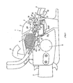
- Fig. 1 shows schematically and in sections a motor chain saw 1 in side view.
- a two-stroke internal combustion engine with a carburetor 3 and cylinder 4.
- a crankshaft (not shown) is driven by the piston of the cylinder 4, which is mounted in a crankshaft housing 5 and a saw chain (not shown) via a pinion drives which rotates on a guide rail 7.
- Two handles 8 and 9 are attached to the housing 2.
- a throttle lever 10 is pivotally mounted about an axis 6.
- the internal combustion engine is started in the usual way via a hand cable (not shown).
- a throttle valve 12 is adjusted via a gas actuation linkage 11, which is pivotally mounted in the intake duct 13 of the carburetor and is loaded by a leg spring (not shown) in the direction of the arrow, that is to say in the closing direction.
- the air flows through the intake duct 13 in the direction of the arrow 14 into the cylinder 4.
- a choke valve 15 is pivotally mounted in front of the throttle valve 12, which in the direction of the arrow, that is to say in the opposite direction to the throttle valve 12 is loaded by a leg spring (not shown); the direction of the arrow corresponds to the closing direction of the choke flap 15.
- the choke flap can be opened against the force of the spring by means of an actuating device 16, the one Bellows 17 contains.
- a rod 18 is fastened, which is guided axially within the bellows and articulates via a coupling member 19 on a lever 20 which is connected in a rotationally fixed manner to the bearing axis 21 of the choke valve 15.
- the throttle valve 12 is coupled to the choke valve 15 via a four-bar linkage 28, as will be explained in more detail below with reference to FIGS. 2 and 3.
- the gas actuating linkage 11 is connected via a pin-slot guide 11A to an actuator 11B, which is seated in a rotationally fixed manner on the bearing axis 22 of the throttle valve 12.
- the bearing axes 21 and 22 lie with their central axes approximately at the level of the longitudinal central axis of the intake duct 13.
- the actuator 11B which is connected in a rotationally fixed manner to the bearing axis 22, is provided with a radially outwardly directed tab 23 on its annular end seated on the bearing axis 22 outer end is bent to a driver 24.
- This driver extends in the axial direction of the bearing axis 22 to beyond a plane in which a lever 25 is pivotable, which is rotatably mounted on the bearing axis 22.
- This lever 25 is articulated via a coupling rod 26 to a lever 27 which is rotatably mounted on the bearing axis 21 of the choke valve 15.
- the two levers 25 and 27 and the coupling rod 26 connecting them form, together with the bearing axles 21 and 22, the four-bar linkage 28 which connects the two flaps 12 and 15.
- the actuating lever 20 of the choke flap 15 is provided at its part-ring-shaped end 20A, which is non-rotatably seated on the bearing axis 21, with two radially outwardly directed tabs 29 and 30, which are also bent into drivers 31 and 32, respectively, which extend in the axial direction of the bearing axis 21 to Extend beyond the pivot plane of the lever 27.
- the control levers 11A and 20 and the four-bar linkage 28 are located next to the housing of the carburetor 3 (see FIG. 3), to which a stop 33 for the lever 27 is attached.
- the Both bearing axles 21 and 22 are led out of the housing of the carburetor 3 for receiving the levers 20, 25 and 27 and the actuator 11B.
- the actuating lever 20 has a shoulder 20B which lies in the path of movement of a shoulder 11C of the actuating linkage 11, which is bent at this point (FIGS. 2 and 3).
- the position of the actuating device 16, the actuator 11B and the actuating lever 20 as well as the linkage 28 according to FIG. 2 corresponds to the standstill of the motor and is shown again in FIG. 4 in order to illustrate the movement sequence when starting the Motors to explain.
- the bellows 17 is fully inflated in the rest position (FIG. 4), so that it has its greatest axial extent.
- the choke flap 15 is in the closed position under the action of the leg spring loading it in the direction of the arrow.
- the throttle valve 12 is also loaded in the direction of the arrow by spring force in the closing direction, but is in the half-open position, which corresponds to an opening angle of approximately 30 °.
- the adjusting lever 20 of the choke valve 15 continues to pivot clockwise, the driver 31 also pivoting the lever 27 of the four-bar linkage clockwise, so that the lever 27 lifts off the stop 33.
- the joint 28A then passes through the dead center position, in which the coupling rod 26 and the lever 27 are in the extended position.
- the actuator 11B can now pivot clockwise under the action of the spring loading the throttle valve 12, whereby it moves by means of the pin-slot guide 11A relative to the gas actuating linkage 11 and pivots the lever 25 via the driver 24.
- the end position reached in this way is shown in FIG. 6.
- the throttle valve 12 is now closed, and the choke valve 15 is in its fully open position in which it is held by the actuating device 16.
- the throttle valve 12 can now be opened as far as desired by means of the gas lever 10 (FIG. 1) via the gas actuating linkage 11 and the actuator 11B, so that the engine can also be operated at full throttle. A mutual influence of the two flaps 12 and 15 is therefore excluded in the operating position of the engine.
- the throttle valve 12 is opened by actuating the gas lever 10 via the gas actuating linkage 11, the choke valve 15 is also held in its open position by means of the linkage 11, which then has a shoulder 11C (see FIG.
- both flaps 12 and 15 can be opened from their then given closed position by actuating the throttle lever via the linkage 11 in order to enable a new start.
- the bellows 17 receives normal pressure again, and the adjusting lever 20 of the choke valve 15 is pivoted counterclockwise via the rod 18 and the coupling member 19 with the cooperation of the spring loading the choke valve.
- the driver 32 of the actuating lever 20 takes the lever 27 of the four-bar linkage 28 with it, so that the link 28A again passes through the dead center position of the linkage and the position according to FIG. 4 is reached again.
- the bellows 17 is connected to the crankshaft housing 5 via a line 34, in which a control unit 35 is located (FIG. 1).
- the bellows 17 is alternately with negative pressure and positive pressure acted upon. When the engine starts, a negative pressure is created in the crankshaft housing 5 and thus a suction in the line 34, so that the bellows 17 is also subjected to negative pressure.
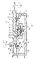
- the control unit 35 is shown in FIGS. 7 and 8 in longitudinal section or in partial longitudinal section. It has a housing 36, which consists of a floor pan 37, a cover 38 and an intermediate wall 39.
- the cover 38 has two connecting pieces 40 and 41.
- the connecting piece 40 serves to connect the section 34A of the line 34 leading to the crankshaft housing 5, and the connecting piece 41 is connected to the line section 34B leading to the bellows 17, as can be seen in FIG. 1 and is indicated schematically in FIG. 7.
- the floor pan 37 forms, together with the intermediate wall 39, a chamber 42 which serves as an air reservoir and is connected to the atmosphere via a throttle bore 43.
- the outer mouth of the throttle bore 43 lies in a recess 44 of the housing wall and is covered there by a sieve 45.
- the connecting piece 40 opens with its bore 40A into a chamber 46, which is formed by the housing cover 38 and the intermediate wall 39 and is connected to the chamber 42 via two bores 47 and 48, which are closed by a mushroom-shaped check valve 49 when the engine is stopped.
- the check valve 49 is made of rubber-elastic material and has a shaft 49A with which it is inserted into a bore 50 of the intermediate wall 39 lying between the bores 47 and 48.
- the shaft 49A lies with its head part 49B sealingly on the edge of the bore 50 on the intermediate wall 39.
- the head part 49B is formed in one piece with the annular valve flap 49C, which covers the two bores 47 and 48 and rests with its edge on the intermediate wall 39 under elastic prestress.
- the stem 49A has near its lower end a thickening 49D with a spherical surface.
- the valve 49 is inserted with its stem 49A into the bore 50 and is then held in its sealing position by means of the thickening 49D.
- the assembly is therefore very simple.
- the connecting piece 41 opens with its bore 41A into a chamber 51 which is formed in the housing cover 38 and is also delimited by the intermediate wall 39.
- the chamber 51 communicates with the air storage chamber 42 via a suction throttle system 52 and two bores 53 and 54, which are closed by a check valve 55 when the engine is at a standstill, the structure and arrangement of which corresponds to the valve 49 already described .
- the suction throttle system 52 includes a chamber 56, which is formed by a trough-shaped depression in the intermediate wall 39 and is delimited by the cover 38.
- a bore 57 emanating from the chamber 51 opens into the chamber 56 and is expanded at the mouth by a recess in the cover 38, in which a sealing ring 58 is arranged.
- a bore 59 Opposite the mouth there is a bore 59 which passes through the intermediate wall 39 and is also widened at its end facing the chamber 56 by a recess in the associated wall; a sealing ring 60 is inserted into this recess.
- One of two slightly curved bimetallic washers 61 and 62 bears against the sealing rings 58 and 60, which are held in position by an S-shaped leaf spring 63.
- each of the two bimetallic disks 61 and 62 there is one of two bores 61A and 62A which are coaxial and together form a throttle bore 64.
- a connecting channel 65 is recessed in the chamber wall formed by the cover 38 and by the intermediate wall 39, which in an operating position of the bimetallic discs 61 and 62 forms a shunt to the throttle bore 64 (FIG. 8).
- the suction throttle system 52 is a thermostatic controller which responds to the temperature of the motor chain saw in the area of the cylinder 4 (FIG. 1).
- the bellows 17 is subjected to negative pressure during operation via the control unit 35 and is ventilated again when the engine is stopped.
- Fig. 7 shows the position of the valves 49 and 55 and the position of the suction throttle system 52 with the engine stopped and a temperature of the device corresponding to the ambient temperature. If the engine is started, a negative pressure is created in the crankshaft housing 5 and thus via the line section 34A in the chamber 46, so that the flap 49C of the valve 49 lifts off and a connection is established between the chambers 46 and 42. As a result, air is sucked out of the bellows 17, in the direction of the arrows through the bores 41A and 57, the throttle bore 64 and through the air storage chamber 42 as well as the bores 47 and 48 and the bore 40A to the crankshaft housing 5.
- throttle bore 43 is dimensioned so that the pressure in the chamber 42 can not drop to the negative pressure in the chamber 46, so that the suction air flow necessary to evacuate the bellows 17 is maintained.
- the flow speed due to the throttle bore 64 is relatively low, so that the choke valve 15 is only opened relatively slowly via the actuating device 16 (FIGS. 2 to 6).
- the two bimetal disks 61 and 62 respond to different temperatures.
- the bimetallic disc which is dimensioned to this value, jumps over, for example the upper disc 61, so that a shunt to the bore 61A in the channel 65 and from there to the bore 62A of the other disk 62 is released and a larger amount of air can be sucked through the chamber 42. If the temperature continues to increase, the other bimetallic disc 62, which reacts to the higher temperature value, also switches over.
- both bimetallic discs 61 and 62 have jumped into their other end positions against the force of the leaf spring 63; this position is shown in FIG. 8, the leaf spring 63 being omitted to simplify the illustration.
- a shunt to both bores 61A and 62A that is to say to the entire throttle bore 64, is opened via the connecting channel 65, so that the flow velocity caused by the suction and thus the velocity of the evacuation of the bellows 17 becomes significantly greater.
- the opening speed of the choke valve 15 is thus increased in two stages, which correspond to two temperature limit values in the area of the cylinder 4. This avoids excessive greasing of the gasoline-air mixture during the starting process, depending on the higher temperatures of the device.
- the ventilation throttle 43 ensures the desired rapid ventilation of the bellows 17, since it ensures a sufficient amount of air or a sufficient pressure in the air storage chamber 42. This ventilation of the chamber 42 via the throttle 43 also prevents the accumulation of liquid in the chamber 42, which could be caused by leakage currents from the crankshaft housing when the valve 49 is opened.
- check valve 49 can be adjusted to a certain pressure difference between the chambers 46 and 42 with regard to its opening behavior, it is also possible to work with a higher negative pressure at a predetermined speed of the engine, thereby improving the functional reliability of the automatic start.
- Another advantage of the control unit 35 is that the construction is simple and less susceptible to faults and does not require very precise manufacturing tolerances, so that the automatic starting system as a whole can be produced very economically.
- another pressure-dependent device could also be provided, for example a pneumatically or pneumatically-hydraulically actuated actuating cylinder, the piston of which is then to be provided with a piston rod for coupling to the actuating lever 20.
Landscapes
- Engineering & Computer Science (AREA)
- Chemical & Material Sciences (AREA)
- Combustion & Propulsion (AREA)
- Mechanical Engineering (AREA)
- General Engineering & Computer Science (AREA)
- Means For Warming Up And Starting Carburetors (AREA)
- Control Of Throttle Valves Provided In The Intake System Or In The Exhaust System (AREA)
Description
Die Erfindung betrifft eine Startautomatik für einen von Hand zu startenden Verbrennungsmotor eines Arbeitsgerätes, beispielsweise einer Motorkettensäge nach dem Oberbegriff des Patentanspruches 1.The invention relates to an automatic starting device for an internal combustion engine of a working device to be started by hand, for example a chain saw according to the preamble of patent claim 1.
Eine derartige Startautomatik ist bekannt (DE-OS 34 45 839). Sie dient dazu, auch für den ungeübten Benutzer eines Gerätes ein einfaches und sicheres Starten des Verbrennungsmotors unabhängig von den Startbedingungen zu ermöglichen. Hierfür ist die automatische Betätigung der Chokeklappe in Abhängigkeit von dem in einem Gehäuseteil des Arbeitsgerätes vorhandenen Unterdruck vorgesehen. Dadurch wird die für die Startphase notwendige Überfettung des Benzin- Luft-Gemisches erreicht, so daß auch beim Start unter ungünstigen Bedingungen, insbesondere bei kaltem Motor, die sonst übliche Betätigung der Chokeklappe von Hand entfällt. Bei der bekannten Startautomatik ist durch die Koppelung der Drosselklappe mit der Choke-Klappe über das Verbindungsgestänge dafür gesorgt, daß in der Schließstellung der Chokeklappe die Drosselklappe teilweise geöffnet ist, beispielsweise auf "Halbgasstellung" steht. Da die Chokeklappe beim Starten in Abhängigkeit von dem dann im Gerätegehäuseteil vorhandenen Unterdruck geöffnet wird, erhält der Motor kurzzeitig nach dem Starten über die dann noch offene Drosselklappe zusätzlich Luft, damit das zunächst überfettete Gemisch verbrannt werden kann. Die Öffnungsbewegung der Chokeklappe ist aber über das Verbindungsgestänge mit der Schließbewegung der Drosselklappe derart gekoppelt, daß diese Schließbewegung zugleich mit der Öffnungsbewegung der Chokeklappe einsetzt. Um trotzdem sicherzustellen, daß die Drosselklappe nach dem Start zum Verbrennen des überfetteten Gemisches genügend lange in ihrer vorgegebenen Öffnungsstellung verbleibt, ist die Betätigungsvorrichtung für die Chokeklappe so ausgebildet, daß sie mit unterschiedlichen Hubgeschwindigkeiten arbeitet; die Öffnungsbewegung der Chokeklappe verläuft dadurch zunächst schnell und wird dann verlangsamt, wobei die Drosselklappe während dieser langsameren Bewegung geschlossen wird. Diese Steuerung erfordert genau aufeinander abgestimmte Bewegungen beider Klappen. Die damit verbundenen Schwierigkeiten in der Fertigung und in der Justierung der Konstruktionsteile werden noch dadurch erhöht, daß die anfängliche Öffnungsbewegung der Chokeklappe temperaturabhängig gesteuert ist, nämlich bei kaltem Motor langsamer und bei warmem oder schon heißem Motor schneller ablaufen soll.Such an automatic start is known (DE-OS 34 45 839). It is used to enable the inexperienced user of a device to start the combustion engine simply and safely, regardless of the starting conditions. For this purpose, the automatic actuation of the choke valve is provided depending on the negative pressure present in a housing part of the implement. As a result, the over-richness of the gasoline-air mixture necessary for the starting phase is achieved, so that the usual operation of the choke flap by hand is also eliminated when starting under unfavorable conditions, especially when the engine is cold. In the known automatic start-up, the coupling of the throttle valve to the choke valve via the connecting linkage ensures that the throttle valve is partially open in the closed position of the choke valve, for example, is at "half-throttle position". Since the choke flap is opened when starting depending on the negative pressure then present in the device housing part, The engine receives additional air shortly after starting via the throttle valve, which is still open, so that the initially over-rich mixture can be burned. The opening movement of the choke valve is coupled via the connecting linkage to the closing movement of the throttle valve in such a way that this closing movement starts at the same time as the opening movement of the choke valve. In order nevertheless to ensure that the throttle valve remains in its predetermined opening position for a sufficiently long time after the start for burning the over-greased mixture, the actuating device for the choke valve is designed such that it operates at different lifting speeds; the opening movement of the choke valve initially runs quickly and is then slowed down, the throttle valve being closed during this slower movement. This control requires precisely coordinated movements of both flaps. The associated difficulties in the manufacture and in the adjustment of the structural parts are further increased by the fact that the initial opening movement of the choke valve is controlled in a temperature-dependent manner, namely to run more slowly when the engine is cold and faster when the engine is warm or already hot.
Der Erfindung liegt daher die Aufgabe zugrunde, die Startautomatik konstruktiv zu vereinfachen und in ihrer Funktion zu verbessern.The invention is therefore based on the object of structurally simplifying the automatic starter and improving its function.
Die Aufgabe wird gemäß der Erfindung mit den kennzeichnenden Merkmalen des Patentanspruches 1 gelöst.The object is achieved according to the invention with the characterizing features of patent claim 1.
Infolge der erfindungsgemäß ausgebildeten Koppelung der Drosselklappe und der Chokeklappe über das Verbindungsgestänge wird die Drosselklappe für einen vorgegebenen Schwenkweg der Chokeklappe mechanisch in ihrer vorgegebenen Öffnungsstellung verriegelt, also beispielsweise in der "Halbgasstellung" gehalten, wodurch sichergestellt ist, daß dem Motor beim Startvorgang genügend Luft zugeführt wird, um die Verbrennung des überfetteten Gemisches zu gewährleisten. Diese Verriegelung ist durch Ausbildung des Verbindungsgestänges konstruktiv einfach zu realisieren. Die teilweise Freigabe des Ansaugkanals durch die entsprechend geöffnete Drosselklappe in Abhängigkeit vom Stellweg der Chokeklappe verbessert außerdem das Startverhalten für den Fall, daß der Motor bereits warm oder heiß ist. Da die Verriegelung über das Verbindungsgestänge gelöst wird, sobald die Chokeklappe einen vorgegebenen Öffnungswinkel erreicht hat, ist nach dem Start, also bei laufendem Motor, eine Betätigung der Drosselklappe mittels des Gashebels in der üblichen Weise möglich, ohne daß sich die Drosselklappe und die Chokeklappe gegenseitig beeinflussen.As a result of the coupling of the throttle valve and the choke valve via the connecting linkage designed according to the invention, the throttle valve is mechanically locked in its predetermined open position for a predetermined pivoting path of the choke valve, that is to say it is held in the "half-throttle position", thereby ensuring that enough air is supplied to the engine during the starting process to ensure the combustion of the over-rich mixture. This locking is easy to implement by constructing the connecting linkage. The partial release of the intake duct by the correspondingly opened throttle valve depending on the travel of the choke valve also improves the starting behavior in the event that the engine is already warm or hot. Since the locking mechanism is released via the connecting linkage as soon as the choke valve has reached a predetermined opening angle, the throttle valve can be actuated in the usual way after the start, i.e. with the engine running, without the throttle valve and the choke valve mutually affecting one another influence.
Weitere Merkmale der Erfindung ergeben sich aus den Unteransprüchen, der folgenden Beschreibung und den Zeichnungen. Es zeigen
- Fig. 1
- eine Motorkettensäge schematisch in einer Teil-Seitenansicht, teilweise aufgeschnitten mit schematischer Darstellung von erfindungswesentlichen Teilen des Vergasers,
- Fig. 2
- den Ansaugkanal des Vergasers schematisch im Axialschnitt und die Betätigungsvorrichtung für die Drosselklappe und die Chokeklappe in Seitenansicht,
- Fig. 3
- eine Ansicht in Richtung des Pfeiles III in Fig. 2,
- Fig. 4 bis Fig. 6
- die Betätigungsvorrichtung für die Drosselklappe und die Chokeklappe in verschiedenen Stellungen, in einer Darstellung entsprechend Fig. 2,
- Fig. 7
- im Längsschnitt eine Steuereinheit mit Ventilen und einer Drossel zur Steuerung der Betätigungsvorrichtung,
- Fig. 8
- eine ausschnittsweise Darstellung der Steuereinheit nach Fig. 7 mit anderer Stellung der Drossel.
- Fig. 1
- a motor chain saw schematically in a partial side view, partially cut away with a schematic representation of parts of the carburetor essential to the invention,
- Fig. 2
- the intake duct of the carburetor schematically in axial section and the actuating device for the throttle valve and the choke valve in a side view,
- Fig. 3
- 2 shows a view in the direction of arrow III in FIG. 2,
- 4 to 6
- the actuating device for the throttle valve and the choke valve in different positions, in a representation corresponding to FIG. 2,
- Fig. 7
- in longitudinal section a control unit with valves and a throttle for controlling the actuating device,
- Fig. 8
- a partial representation of the control unit of FIG. 7 with a different position of the throttle.
Fig. 1 zeigt schematisch und ausschnittsweise eine Motorkettensäge 1 in Seitenansicht. Im Gehäuse 2 der Motorkettensäge befindet sich ein Zweitakt-Verbrennungsmotor mit einem Vergaser 3 und Zylinder 4. Vom Kolben des Zylinders 4 wird eine (nicht dargestellte) Kurbelwelle angetrieben, die in einem Kurbelwellengehäuse 5 gelagert ist und über ein Ritzel eine (nicht dargestellte) Sägekette antreibt, die auf einer Führungsschiene 7 umläuft. Am Gehäuse 2 sind zwei Haltegriffe 8 und 9 befestigt. In dem hinteren Haltegriff 9 ist ein Gashebel 10 um eine Achse 6 schwenkbar gelagert. Der Verbrennungsmotor wird in üblicher Weise über einen (nicht dargestellten) Handseilzug gestartet. Mit dem Gashebel 10 wird über ein Gas-Betätigungsgestänge 11 eine Drosselklappe 12 verstellt, die im Ansaugkanal 13 des Vergasers schwenkbar gelagert und von einer (nicht dargestellten) Schenkelfeder in Richtung des eingetragenen Pfeiles, also in Schließrichtung belastet ist. Die Luft strömt durch den Ansaugkanal 13 hindurch in Richtung des Pfeiles 14 in den Zylinder 4. Im Ansaugkanal ist - bezogen auf die Strömungsrichtung 14 - vor der Drosselklappe 12 eine Chokeklappe 15 schwenkbar gelagert, die in Richtung des eingetragenen Pfeiles, also gegensinnig zur Drosselklappe 12, durch eine (nicht dargestellte) Schenkelfeder belastet ist; die Pfeilrichtung entspricht der Schließrichtung der Chokeklappe 15. Die Chokeklappe kann gegen die Kraft der Feder mittels einer Betätigungsvorrichtung 16 geöffnet werden, die einen Faltenbalg 17 enthält. Am oberen Ende des Faltenbalgs ist eine Stange 18 befestigt, die innerhalb des Faltenbalgs axial geführt ist und über ein Koppelglied 19 gelenkig an einem Hebel 20 angreift, der drehfest mit der Lagerachse 21 der Chokeklappe 15 verbunden ist. Die Drosselklappe 12 ist mit der Chokeklappe 15 über ein Viergelenk-Gestänge 28 gekoppelt, wie im folgenden anhand der Fig. 2 und 3 näher erläutert wird.Fig. 1 shows schematically and in sections a motor chain saw 1 in side view. In the
Das Gas-Betätigungsgestänge 11 ist über eine Stift-Schlitz-Führung 11A mit einem Stellglied 11B verbunden, das drehfest auf der Lagerachse 22 der Drosselklappe 12 sitzt. Die Lagerachsen 21 und 22 liegen mit ihren Mittelachsen etwa in Höhe der Längsmittelachse des Ansaugkanals 13. Das mit der Lagerachse 22 drehfest verbundene Stellglied 11B ist an seinem ringförmigen, auf der Lagerachse 22 sitzenden Ende mit einem radial nach außen gerichteten Lappen 23 versehen, der am äußeren Ende zu einem Mitnehmer 24 abgekröpft ist. Dieser Mitnehmer erstreckt sich in Achsrichtung der Lagerachse 22 bis über eine Ebene hinaus, in der ein Hebel 25 schwenkbar ist, der auf der Lagerachse 22 drehbar gelagert ist. Dieser Hebel 25 ist über eine Koppelstange 26 gelenkig mit einem Hebel 27 verbunden, der drehbar auf der Lagerachse 21 der Chokeklappe 15 gelagert ist. Die beiden Hebel 25 und 27 und die sie verbindende Koppelstange 26 bilden zusammen mit den Lagerachsen 21 und 22 das Viergelenk-Gestänge 28, das die beiden Klappen 12 und 15 verbindet. Der Betätigungshebel 20 der Chokeklappe 15 ist an seinem teilringförmigen, drehfest auf der Lagerachse 21 sitzenden Ende 20A mit zwei radial nach außen gerichten Lappen 29 und 30 versehen, die ebenfalls zu Mitnehmern 31 bzw. 32 abgekröpft sind, welche sich in Achsrichtung der Lagerachse 21 bis über die Schwenkebene des Hebels 27 hinaus erstrecken. Die Stellhebel 11A und 20 sowie das Viergelenk-Gestänge 28 liegen neben dem Gehäuse des Vergasers 3 (vgl. Fig. 3), an dem ein Anschlag 33 für den Hebel 27 befestigt ist. Die beiden Lagerachsen 21 und 22 sind zur Aufnahme der Hebel 20, 25 und 27 sowie des Stellgliedes 11B aus dem Gehäuse des Vergasers 3 herausgeführt.The gas actuating
Der Stellhebel 20 hat einen Ansatz 20B, der im Bewegungsweg einer Schulter 11C des Betätigungsgestänges 11 liegt, das an dieser Stelle abgekröpft ist (Fig. 2 und 3).The actuating
Die Stellung der Betätigungsvorrichtung 16, des Stellgliedes 11B und des Stellhebels 20 sowie des Gestänges 28 nach Fig. 2 entspricht dem Stillstand des Motors und ist nochmals in Fig. 4 dargestellt, um in Verbindung mit den Fig. 5 und 6 den Bewegungsablauf beim Starten des Motors zu erläutern. Der Faltenbalg 17 ist in der Ruhestellung (Fig. 4) voll aufgeblasen, wobei er also seine größte axiale Erstreckung hat. Die Chokeklappe 15 befindet sich unter der Wirkung der sie in Pfeilrichtung belastenden Schenkelfeder in Schließstellung. Die Drosselklappe 12 ist ebenfalls in Richtung des eingetragenen Pfeiles durch Federkraft in Schließrichtung belastet, befindet sich jedoch in halb geöffneter Stellung, was einem Öffnungswinkel von etwa 30° entspricht. In dieser Stellung wird die Drosselklappe durch das Viergelenk-Gestänge 28 gehalten, das mit seinem die Koppelstange 26 mit dem Hebel 27 verbindenden Gelenk 28A über eine Totpunktlage hinaus entgegen dem Uhrzeigersinn verschwenkt ist, wobei der Hebel 27 an dem Anschlag 33 anliegt. Infolge dieser Durchknickung des Gelenkgestänges im Gelenk 28A und der Anlage des Hebels 27 am Anschlag 33 hat das Viergelenk-Gestänge eine quasi stabile Lage. Daher kann der Mitnehmer 24 des Stellgliedes 11B, der unter der die Drosselklappe 12 belastenden Federkraft an dem Hebel 25 des Viergelenk-Gestänges 28 anliegt, die Drosselklappe 12 nicht aus ihrer in Fig. 4 dargestellten, halb geöffneten Stellung in die Schließlage schwenken.The position of the
Wird der Motor gestartet, so entsteht in dem Faltenbalg 17 ein Unterdruck, wie im einzelnen später beschrieben wird. Der Faltenbalg zieht sich dadurch zusammen; die entsprechende Zwischenstellung ist in Fig. 5 gezeigt. Der Hebel 20 wird dabei über die Stange 18 und das Koppelglied 19 gegen die Kraft der die Chokeklappe 15 belastenden Feder im Uhrzeigersinn verschwenkt, so daß die Chokeklappe 15 geöffnet wird. Das Viergelenk-Gestänge 28 bleibt dabei zunächst in seiner Lage, so daß die Öffnungsstellung der Drosselklappe 12 zunächst ebenfalls unverändert bleibt, bis der Mitnehmer 31 des Stellhebels 20 auf den Hebel 27 des Viergelenk-Gestänges auftrifft. Diese Stellung zeigt Fig. 5.When the engine is started, a vacuum is created in the
Mit zunehmendem Unterdruck in dem Balg 17 schwenkt der Stellhebel 20 der Chokeklappe 15 weiter im Uhrzeigersinn, wobei der Mitnehmer 31 den Hebel 27 des Viergelenk-Gestänges ebenfalls im Uhrzeigersinn verschwenkt, so daß der Hebel 27 von dem Anschlag 33 abhebt. Das Gelenk 28A durchläuft dann die Totpunktstellung, in der sich die Koppelstange 26 und der Hebel 27 in Strecklage befinden. Das Stellglied 11B kann nun unter der Wirkung der die Drosselklappe 12 belastenden Feder im Uhrzeigersinn verschwenken, wobei es sich mittels der Stift-Schlitz-Führung 11A relativ zu dem Gas-Betätigungsgestänge 11 bewegt und den Hebel 25 über den Mitnehmer 24 verschwenkt.With increasing negative pressure in the
Die auf diese Weise erreichte Endlage zeigt Fig. 6. Die Drosselklappe 12 ist nun geschlossen, und die Chokeklappe 15 befindet sich in ihrer vollständig geöffneten Lage, in der sie von der Betätigungsvorrichtung 16 gehalten wird. Die Drosselklappe 12 kann nun mittels des Gashebels 10 (Fig. 1) über das Gas-Betätigungsgestänge 11 und das Stellglied 11B beliebig weit geöffnet werden, so daß der Motor auch mit Vollgas betrieben werden kann. Eine gegenseitige Beeinflussung der beiden Klappen 12 und 15 ist daher in der Betriebsstellung des Motors ausgeschlossen. Ist die Drosselklappe 12 durch Betätigen des Gashebels 10 über das Gas-Betätigungsgestänge 11 geöffnet, so wird die Chokeklappe 15 in ihrer geöffneten Stellung auch mittels des Gestänges 11 gehalten, das mit seiner Schulter 11C (vgl. Fig. 2) dann an dem Ansatz 20B des Stellhebels 20 anliegt und dadurch ein Zurückschwenken dieses Hebels verhindert. Die Kröpfung des Gestänges 11 mit der Schulter 11C ermöglicht auch im Zusammenwirken mit dem Ansatz 20B des Stellhebels 20 einen sogenannten Notstart. Ist nämlich der Motor durch Überfettung des Benzin-Luft-Gemisches ungewollt zum Stillstand gekommen, so können beide Klappen 12 und 15 aus ihrer dann gegebenen Schließstellung durch Betätigen des Gashebels über das Gestänge 11 geöffnet werden, um den erneuten Start zu ermöglichen.The end position reached in this way is shown in FIG. 6. The
Wird der Motor stillgesetzt, so erhält der Faltenbalg 17 wieder normalen Druck, und über die Stange 18 und das Koppelglied 19 wird der Stellhebel 20 der Chokeklappe 15 unter Mitwirkung der die Chokeklappe belastenden Feder entgegen dem Uhrzeigersinn verschwenkt. Dabei nimmt der Mitnehmer 32 des Stellhebels 20 den Hebel 27 des Viergelenk-Gestänges 28 mit, so daß das Gelenk 28A erneut die Totpunktlage des Gestänges durchläuft und die Stellung nach Fig. 4 wieder erreicht wird.When the engine is stopped, the
Da die beschriebene Startautomatik dafür sorgt, daß die Drosselklappe 12 während des Startvorganges in Abhängigkeit von einem vorgegebenen Stellweg der Chokeklappe 15 in ihrer halb geöffneten Stellung verbleibt, erhält der Motor genügend Luft, um das zunächst überfettete Benzin- Luft-Gemisch zu verbrennen.Since the described automatic start ensures that the
Zur Steuerung der Betätigungsvorrichtung 16 ist der Faltenbalg 17 an das Kurbelwellengehäuse 5 über eine Leitung 34 angeschlossen, in der eine Steuereinheit 35 liegt (Fig. 1). Der Faltenbalg 17 wird abwechselnd mit Unterdruck und Überdruck beaufschlagt. Beim Anlaufen des Motors entsteht im Kurbelwellengehäuse 5 ein Unterdruck und damit in der Leitung 34 ein Sog, so daß der Faltenbalg 17 dabei ebenfalls mit Unterdruck beaufschlagt wird.To control the
Die Steuereinheit 35 ist in den Fig. 7 und 8 im Längsschnitt bzw. im Teil-Längsschnitt dargestellt. Sie hat ein Gehäuse 36, das aus einer Bodenwanne 37, einem Deckel 38 und einer Zwischenwand 39 besteht. Der Deckel 38 weist zwei Anschlußstutzen 40 und 41 auf. Der Anschlußstutzen 40 dient zum Anschluß des zum Kurbelwellengehäuse 5 führenden Abschnittes 34A der Leitung 34, und an den Anschlußstutzen 41 ist der zum Faltenbalg 17 führende Leitungsabschnitt 34B angeschlossen, wie aus Fig. 1 ersichtlich und in Fig. 7 schematisch angedeutet ist. Die Bodenwanne 37 bildet zusammen mit der Zwischenwand 39 eine Kammer 42, die als Luftspeicher dient und mit der Atmosphäre über eine Drosselbohrung 43 verbunden ist. Die äußere Mündung der Drosselbohrung 43 liegt in einer Vertiefung 44 der Gehäusewandung und ist dort von einem Sieb 45 abgedeckt.The
Der Anschlußstutzen 40 mündet mit seiner Bohrung 40A in eine Kammer 46, die von dem Gehäusedeckel 38 und der Zwischenwand 39 gebildet und mit der Kammer 42 über zwei Bohrungen 47 und 48 verbunden ist, die bei Stillstand des Motors durch ein pilzförmiges Rückschlagventil 49 verschlossen sind. Das Rückschlagventil 49 besteht aus gummielastischem Werkstoff und hat einen Schaft 49A, mit dem es in eine zwischen den Bohrungen 47 und 48 liegende Bohrung 50 der Zwischenwand 39 eingesetzt ist. Der Schaft 49A liegt mit seinem Kopfteil 49B dichtend am Rand der Bohrung 50 auf der Zwischenwand 39 auf. Das Kopfteil 49B ist einstückig mit der ringförmigen Ventilklappe 49C ausgebildet, welche die beiden Bohrungen 47 und 48 überdeckt und mit ihrem Rand unter elastischer Vorspannung auf der Zwischenwand 39 aufliegt. Der Schaft 49A hat in der Nähe seines unteren Endes eine Verdickung 49D mit kugeliger Oberfläche. Bei der Montage wird das Ventil 49 mit seinem Schaft 49A in die Bohrung 50 eingesteckt und ist dann mittels der Verdickung 49D in seiner dichtenden Lage gehalten. Die Montage ist daher sehr einfach.The connecting
Der Anschlußstutzen 41 mündet mit seiner Bohrung 41A in eine Kammer 51, die im Gehäusedeckel 38 ausgebildet und ebenfalls durch die Zwischenwand 39 begrenzt ist. Die Kammer 51 steht mit der Luftspeicher-Kammer 42 über ein Saugdrossel-System 52 und zwei Bohrungen 53 und 54 in Verbindung, die bei Stillstand des Motors von einem Rückschlagventil 55 verschlossen sind, das in seinem Aufbau und seiner Anordnung dem schon beschriebenen Ventil 49 entspricht.The connecting piece 41 opens with its
Zum Saugdrossel-System 52 gehört eine Kammer 56, die von einer wannenförmigen Vertiefung der Zwischenwand 39 gebildet und durch den Deckel 38 begrenzt ist. In die Kammer 56 mündet eine von der Kammer 51 ausgehende Bohrung 57, die an der Mündung durch eine Vertiefung im Deckel 38 erweitert ist, in welcher ein Dichtring 58 angeordnet ist. Der Mündung gegenüber liegt eine Bohrung 59, welche die Zwischenwand 39 durchsetzt und an ihrem der Kammer 56 zugewandten Ende ebenfalls durch eine Vertiefung in der zugehörigen Wandung erweitert ist; in diese Vertiefung ist ein Dichtring 60 eingelegt. An den Dichtringen 58 und 60 liegt je eine von zwei leicht gewölbten Bimetall-Scheiben 61 und 62 an, die durch eine S-förmige Blattfeder 63 in ihrer Lage gehalten sind. In den beiden Bimetall-Scheiben 61 und 62 ist je eine von zwei Bohrungen 61A und 62A vorhanden, die koaxial liegen und gemeinsam eine Drosselbohrung 64 bilden. An einer Seite der Kammer 56 ist in der vom Deckel 38 und von der Zwischenwand 39 gebildeten Kammerwandung ein Verbindungskanal 65 ausgespart, der in einer Betriebslage der Bimetall-Scheiben 61 und 62 einen Nebenschluß zu der Drosselbohrung 64 bildet (Fig. 8).The
Das Saugdrossel-System 52 ist ein thermostatischer Regler, der auf die im Bereich des Zylinders 4 (Fig. 1) vorhandene Temperatur der Motorkettensäge anspricht.The
Über die Steuereinheit 35 wird der Faltenbalg 17 im Betrieb mit Unterdruck beaufschlagt und bei Stillstand des Motors wieder belüftet.The bellows 17 is subjected to negative pressure during operation via the
Fig. 7 zeigt die Lage der Ventile 49 und 55 sowie die Stellung des Saugdrossel-Systems 52 bei stillstehendem Motor und einer der Umgebungstemperatur entsprechenden Temperatur des Gerätes. Wird der Motor gestartet, so entsteht im Kurbelwellengehäuse 5 und damit über den Leitungsabschnitt 34A in der Kammer 46 ein Unterdruck, so daß die Klappe 49C des Ventils 49 abhebt und eine Verbindung zwischen den Kammern 46 und 42 hergestellt ist. Dadurch wird aus dem Faltenbalg 17 Luft abgesaugt, und zwar in Richtung der eingetragenen Pfeile durch die Bohrungen 41A und 57, die Drosselbohrung 64 und durch die Luftspeicher-Kammer 42 sowie die Bohrungen 47 und 48 und die Bohrung 40A hindurch zum Kurbelwellengehäuse 5. Die von der Atmosphäre in die Luftspeicher-Kammer 42 mündende Drosselbohrung 43 ist so dimensioniert, daß der Druck in der Kammer 42 nicht bis auf den Unterdruck in der Kammer 46 absinken kann, so daß die zum Evakuieren des Faltenbalges 17 notwendige Saug-Luftströmung aufrechterhalten bleibt. Bei noch kaltem Gerät ist die Strömungsgeschwindigkeit infolge der Drosselbohrung 64 verhältnismäßig gering, so daß die Chokeklappe 15 über die Betätigungsvorrichtung 16 (Fig. 2 bis 6) nur relativ langsam geöffnet wird. Die beiden Bimetall-Scheiben 61 und 62 sprechen auf unterschiedliche Temperaturen an. Steigt die Temperatur im Bereich des Zylinders 4 auf einen bestimmten Wert, so springt die auf diesen Wert bemessene Bimetall-Scheibe um, beispielsweise die obere Scheibe 61, so daß ein Nebenschluß zu der Bohrung 61A in den Kanal 65 und von dort zu der Bohrung 62A der anderen Scheibe 62 freigegeben wird und eine größere Luftmenge durch die Kammer 42 hindurch abgesaugt werden kann. Nimmt die Temperatur weiter zu, so springt auch die andere Bimetall-Scheibe 62 um, die auf den höheren Temperaturwert reagiert. Sobald daher die Motorkettensäge im Bereich des Zylinders 4 die höhere Schalttemperatur des vom Saugdrossel-System 52 gebildeten Thermostaten erreicht hat, sind beide Bimetall-Scheiben 61 und 62 gegen die Kraft der Blattfeder 63 in ihre andere Endlage umgesprungen; diese Stellung ist in Fig. 8 gezeigt, wobei die Blattfeder 63 zur Vereinfachung der Darstellung weggelassen ist. In dieser Stellung der Bimetall-Scheiben ist ein Nebenschluß zu beiden Bohrungen 61A und 62A, also zur gesamten Drosselbohrung 64 über den Verbindungskanal 65 geöffnet, so daß die durch den Sog verursachte Strömungsgeschwindigkeit und damit die Geschwindigkeit der Evakuierung des Faltenbalges 17 wesentlich größer wird. Die Öffnungsgeschwindigkeit der Chokeklappe 15 wird also in zwei Stufen erhöht, die zwei Temperatur-Grenzwerten im Bereich des Zylinders 4 entsprechen. Damit wird eine zu starke Überfettung des Benzin-Luft-Gemisches während des Startvorganges in Abhängigkeit von den höheren Temperaturen des Gerätes vermieden.Fig. 7 shows the position of the
Wird der Motor stillgesetzt, so steigt der Druck im Kurbelwellengehäuse 5 wieder auf den Normalwert an, und das Ventil 49 schließt die Verbindung zwischen den Kammern 46 und 42. Dadurch entsteht ein Sog in Richtung zu dem Faltenbalg 17, der noch mit Unterdruck beaufschlagt ist. Aus der Luftspeicher-Kammer 42 strömt dann Luft durch das Saugdrossel-System 52 und gegebenenfalls durch den Verbindungskanal 65 in die Bohrung 57 und von dort über den Leitungsabschnitt 34B in den Faltenbalg 17. Die Belüftung des Faltenbalges wird dadurch beschleunigt, daß das Ventil 55 infolge des Druckunterschiedes zwischen den Kammern 51 und 42 öffnet, so daß die Luft aus der Kammer 42 auch über die Bohrungen 53 und 54 in Richtung auf den Faltenbalg 17 abströmen kann. Die Belüftungsdrossel 43 gewährleistet das gewünschte schnelle Belüften des Faltenbalges 17, da sie für eine ausreichende Luftmenge bzw. einen ausreichenden Druck in der Luftspeicher-Kammer 42 sorgt. Diese Belüftung der Kammer 42 über die Drossel 43 verhindert auch die Ansammlung von Flüssigkeit in der Kammer 42, die durch Leckströme aus dem Kurbelwellengehäuse beim Öffnen des Ventils 49 entstehen könnten.If the engine is stopped, the pressure in the
Da das Rückschlagventil 49 hinsichtlich seines Öffnungsverhaltens auf eine bestimmte Druckdifferenz zwischen den Kammern 46 und 42 abgestimmt werden kann, ist es auch möglich, bei einer vorgegebenen Drehzahl des Motors mit höherem Unterdruck zu arbeiten, wodurch die Funktionssicherheit der Startautomatik verbessert wird. Ein weiterer Vorteil der Steuereinheit 35 besteht darin, daß die Konstruktion einfach und wenig störanfällig ist sowie keine sehr genauen Fertigungstoleranzen erfordert, so daß die Startautomatik insgesamt sehr wirtschaftlich herzustellen ist.Since the
Anstelle des Faltenbalges könnte auch eine andere druckabhängige Vorrichtung vorgesehen sein, beispielsweise ein pneumatisch oder pneumatisch-hydraulisch zu betätigender Stellzylinder, dessen Kolben dann mit einer Kolbenstange zur Koppelung mit dem Stellhebel 20 zu versehen ist.Instead of the bellows, another pressure-dependent device could also be provided, for example a pneumatically or pneumatically-hydraulically actuated actuating cylinder, the piston of which is then to be provided with a piston rod for coupling to the
Claims (14)
- Starting device for a hand-started internal combustion engine of a tool, for example of a power chain saw, with a throttle valve (12) and choke valve (15) respectively seated on a bearing shaft (1, 22), which are arranged one behind the other in the direction of flow in the induction port (13) of a carburettor and are connected to each other by way of a connecting linkage (28) so that when the choke valve is closed, the throttle valve is kept in a partly open position, and with an actuating device (16) associated with the choke valve, which device engages on a control lever (20) seated in a non-rotary manner on the bearing shaft (21) of the choke valve and can be acted upon by reduced pressure in a housing part (5) of the tool by way of a pipe (34), which contains a non-return valve (49) and a thermostatically controlled throttle (52), and with a manually actuated gas lever (10), which is connected to a control member (11B) seated in a non-rotary manner on the bearing shaft (22) of the throttle valve, characterised in that the throttle valve (12) and choke valve (15) are connected by way of the connecting linkage (28) so that the throttle valve (12) remains in its partly open position up to a predetermined opening angle of the choke valve (15).
- Starting device according to Claim 1, characterised in that the connecting linkage is a four-bar linkage (28), which can be swung beyond a dead-centre position by means of the control lever (20) seated on the bearing shaft (21) of the choke valve (15) and in its one end position, which corresponds to the predetermined partially open position of the throttle valve (12), is held by a stop (33) in this position locking the throttle valve (12).
- Starting device according to Claim 2, characterised in that the four-bar linkage (29) contains two levers (25 and 27), which are respectively mounted to rotate on one of the two bearing shafts (21 and 22) of the two valves (choke valve 15 and throttle valve 12) and are connected by a connecting rod (26).
- Starting device according to Claim 3, characterised in that the dead-centre position of the four-bar linkage (28) is defined by the extended position of one of the two levers (27) with the connecting rod (26).
- Starting device according to Claim 3 or 4, characterised in that the control lever (20) seated on the bearing shaft (21) of the choke valve (15) comprises two entrainment members (31 and 32) for the lever (27) of the four-bar linkage (28) mounted on the same bearing shaft (21) and that the entrainment member (31), by which the locking end position of the four-bar linkage (28) is released at the time of tilting of the control lever (20), in the closed position of the choke valve (15) is at a distance from the lever (27) of the four-bar linkage (28), which corresponds to the predetermined opening angle of the choke valve (15), up to which the throttle valve (12) maintains its partly open position.
- Starting device according to Claim 5, characterised in that the second entrainment member (32) of the control lever (20) of the choke valve (15) defines the swinging displacement of the lever (27) in the completely open position of the choke valve (15).
- Starting device according to one of Claims 1 to 6, characterised in that the throttle valve (12) and the choke valve (15) are able to swing into their closed positions in opposite directions under the force of a spring.
- Starting device according to one of Claims 3 to 7, characterised in that the control member (11B) for the throttle valve (12) comprises an entrainment member (24), which under the spring force acting in the closing direction of the throttle valve (12) bears against the lever (25) of the four-bar linkage (28), which is mounted on the bearing shaft (22) of the throttle valve (12).
- Starting device according to one of Claims 1 to 8, characterised in that the actuating device (16) of the control lever (20) of the choke valve (15) to be acted upon by reduced pressure from the housing part (5) of the tool (1) is controlled by way of a control unit (35), which lies in the connecting line (34) between the housing part (5) and the actuating device (16) and contains the non-return valve (49) and an air storage chamber (42), which is connected by way of the non-return valve (49) to a chamber (46) receiving reduced pressure and from which the actuating device (16) is supplied with air when the reduced pressure is eliminated.
- Starting device according to Claim 9, characterised in that the thermostatically controlled throttle is formed by a suction throttle system (52), which connects a bore (57) in the housing (36) of the control unit (35) to the air-storage chamber (42) and that connected to the housing bore (57) is the section (34B) of the connecting pipe (34) leading to the actuating device (16).
- Starting device according to Claim 10, characterised in that the housing bore (57) opens into a chamber (56) and at the opening point lies coaxial to a bore (59), which connects this chamber (56) to the air-storage chamber (42), and that the suction throttle system (52) comprises two curved bimetallic discs (61 and 62) lying within the chamber (56), which lie opposite each other and are each braced against one of the two chamber walls penetrated by the bores (57 and 59), whereby in their one end position they respectively bear against a gasket (58 or 60) surrounding the associated bore opening, that the two bimetallic discs (61 and 62) each comprise a central bore (61A; 62A) for forming a throttle bore (64) and that provided in one side wall of the chamber (56) is a connecting channel (65), which is released in a temperature-dependent manner by one of the two bimetallic discs (61 and 62) or by both bimetallic discs (61 and 62) in its other end position reached after exceeding a temperature limit value, as a partial or complete by-pass to the throttle bore (64).
- Starting device according to one of Claims 9 to 11, characterised in that the air-storage chamber (42) is connected to the atmosphere by way of a throttle bore (43).
- Starting device according to one of Claims 10 to 12, characterised in that the housing bore (57), to which the pipe section (34B) leading to the actuating device (16) is connected, is enlarged to form a chamber (51) in the region between the suction throttle system (52) and the connection point (41) of the pipe section (34B), which chamber is connected to the air-storage chamber (42) by way of a second non-return valve (55).
- Starting device according to Claim 13, characterised in that the two non-return valves (49 and 55) consist of resilient rubber material and each comprise a shaft (49A) with a head part (49B), adjoining which is an annular valve flap (49C), which covers two through bores (47 and 48; 53 and 54) provided in the respective housing wall, between which a receiving bore (50) for the shaft (49A) is provided, at one end of which the head part (49B) is located and at the other end of which a thickened portion (49D) of the shaft (49A) is located, by which the valve (49; 55) is clamped in the receiving bore (50).
Applications Claiming Priority (2)
| Application Number | Priority Date | Filing Date | Title |
|---|---|---|---|
| US07/062,121 US4773362A (en) | 1984-12-15 | 1987-06-15 | Automatic starting arrangement for an internal combustion engine |
| US62121 | 1987-06-15 |
Publications (3)
| Publication Number | Publication Date |
|---|---|
| EP0295398A2 EP0295398A2 (en) | 1988-12-21 |
| EP0295398A3 EP0295398A3 (en) | 1989-11-15 |
| EP0295398B1 true EP0295398B1 (en) | 1991-09-18 |
Family
ID=22040354
Family Applications (1)
| Application Number | Title | Priority Date | Filing Date |
|---|---|---|---|
| EP19880106626 Expired - Lifetime EP0295398B1 (en) | 1987-06-15 | 1988-04-26 | Starting device for an internal combustion engine, especially for a hand-started motor of a tool |
Country Status (5)
| Country | Link |
|---|---|
| EP (1) | EP0295398B1 (en) |
| JP (1) | JPS6419159A (en) |
| AU (1) | AU610185B2 (en) |
| CA (1) | CA1305376C (en) |
| DE (1) | DE3864914D1 (en) |
Families Citing this family (1)
| Publication number | Priority date | Publication date | Assignee | Title |
|---|---|---|---|---|
| US5882867A (en) * | 1995-06-07 | 1999-03-16 | Dade Behring Marburg Gmbh | Detection of nucleic acids by formation of template-dependent product |
Family Cites Families (6)
| Publication number | Priority date | Publication date | Assignee | Title |
|---|---|---|---|---|
| US2957465A (en) * | 1958-05-23 | 1960-10-25 | Gen Motors Corp | Fast opening choke mechanism |
| FR79550E (en) * | 1961-04-15 | 1962-12-14 | Sibe | Improvements to carburettors fitted with an automatically controlled auxiliary starting device |
| US4382899A (en) * | 1981-12-11 | 1983-05-10 | Schmelzer Corporation | Temperature responsive time delay valve |
| FR2522729A1 (en) * | 1982-03-04 | 1983-09-09 | Renault | PNEUMATIC CONTROL DEVICE FOR THE AIR FLAP OF A CARBURETOR FOR AN INTERNAL COMBUSTION ENGINE |
| US4643352A (en) * | 1984-12-03 | 1987-02-17 | Tom Mcguane Industries, Inc. | Temperature compensating vacuum delay valve |
| DE3445839C2 (en) * | 1984-12-15 | 1997-03-13 | Stihl Maschf Andreas | Automatic start for an internal combustion engine, in particular the engine of a chain saw |
-
1988
- 1988-04-26 EP EP19880106626 patent/EP0295398B1/en not_active Expired - Lifetime
- 1988-04-26 DE DE8888106626T patent/DE3864914D1/en not_active Expired - Fee Related
- 1988-06-14 CA CA000569370A patent/CA1305376C/en not_active Expired - Fee Related
- 1988-06-14 JP JP14490388A patent/JPS6419159A/en active Pending
- 1988-06-14 AU AU17646/88A patent/AU610185B2/en not_active Ceased
Also Published As
| Publication number | Publication date |
|---|---|
| AU610185B2 (en) | 1991-05-16 |
| EP0295398A2 (en) | 1988-12-21 |
| EP0295398A3 (en) | 1989-11-15 |
| DE3864914D1 (en) | 1991-10-24 |
| AU1764688A (en) | 1988-12-15 |
| CA1305376C (en) | 1992-07-21 |
| JPS6419159A (en) | 1989-01-23 |
Similar Documents
| Publication | Publication Date | Title |
|---|---|---|
| DE69810850T2 (en) | Exhaust gas recirculation valve | |
| DE19500475C2 (en) | Shut-off or throttle valve with rotatable valve flap | |
| DE68908182T2 (en) | TURBOCHARGER WITH DUAL FUNCTION TRIGGER. | |
| DE102017105889A1 (en) | Valve in an exhaust pipe and appropriate assembly process | |
| DE3445839C2 (en) | Automatic start for an internal combustion engine, in particular the engine of a chain saw | |
| DE2511288C2 (en) | Device for the automatic actuation of the air flaps of carburetors | |
| EP2017456A1 (en) | Exhaust gas recirculation system | |
| DE2359809A1 (en) | DEVICE FOR REGULATING THE RECIRCULATION OF THE EXHAUST GASES OF A COMBUSTION ENGINE | |
| DE102020108125A1 (en) | CONNECTING ARRANGEMENT AND TURBOCHARGER INCLUDING THE CONNECTING ARRANGEMENT | |
| DE655070C (en) | Power steering for the steering of motor vehicles | |
| EP0080070B1 (en) | Internal-combustion engine | |
| DE102008034341A1 (en) | Double flap valve arrangement for exhaust gas stream in exhaust system of internal combustion engine of motor vehicle, has plates arranged section wise transverse to flow direction in open position of arrangement | |
| DE19636811C2 (en) | Automatic decompression | |
| DE2509625A1 (en) | ACTUATING DEVICE FOR THE AIR FLAP OF A CARBURETTOR | |
| EP0295398B1 (en) | Starting device for an internal combustion engine, especially for a hand-started motor of a tool | |
| DE2261650A1 (en) | ACTUATING DEVICE FOR THE AIR FLAP OF A CARBURETTOR | |
| EP0020791B1 (en) | Device for controlling a valve disposed in the charge air conduit of a combustion engine | |
| WO2023025565A1 (en) | Valve bridge for a valve train of an internal combustion engine, in particular of a motor vehicle, and internal combustion engine | |
| DE202009000831U1 (en) | Carburettor unit for a motor unit | |
| DE2624210C2 (en) | Device for regulating the temperature of the intake air of mixture-compressing internal combustion engines | |
| DE943158C (en) | Device for the automatic adjustment of the flaps of radiator blinds for motor vehicles | |
| DE4208045A1 (en) | Non-return air flow control valve for catalytic converter - has disc valve stage with coupled diaphragm actuator | |
| DE2525594A1 (en) | Vehicle engine automatic cold start system - choke and throttle flaps are turned by temperature dependent stepping motor | |
| DE878308C (en) | Control device for motor vehicle clutches | |
| DE2452341A1 (en) | COLD START DEVICE FOR CARBURETTORS IN COMBUSTION ENGINES |
Legal Events
| Date | Code | Title | Description |
|---|---|---|---|
| PUAI | Public reference made under article 153(3) epc to a published international application that has entered the european phase |
Free format text: ORIGINAL CODE: 0009012 |
|
| AK | Designated contracting states |
Kind code of ref document: A2 Designated state(s): DE FR GB IT SE |
|
| PUAL | Search report despatched |
Free format text: ORIGINAL CODE: 0009013 |
|
| AK | Designated contracting states |
Kind code of ref document: A3 Designated state(s): DE FR GB IT SE |
|
| 17P | Request for examination filed |
Effective date: 19891102 |
|
| 17Q | First examination report despatched |
Effective date: 19910214 |
|
| GRAA | (expected) grant |
Free format text: ORIGINAL CODE: 0009210 |
|
| AK | Designated contracting states |
Kind code of ref document: B1 Designated state(s): DE FR GB IT SE |
|
| ET | Fr: translation filed | ||
| REF | Corresponds to: |
Ref document number: 3864914 Country of ref document: DE Date of ref document: 19911024 |
|
| ITF | It: translation for a ep patent filed | ||
| GBT | Gb: translation of ep patent filed (gb section 77(6)(a)/1977) | ||
| PLBE | No opposition filed within time limit |
Free format text: ORIGINAL CODE: 0009261 |
|
| STAA | Information on the status of an ep patent application or granted ep patent |
Free format text: STATUS: NO OPPOSITION FILED WITHIN TIME LIMIT |
|
| 26N | No opposition filed | ||
| EAL | Se: european patent in force in sweden |
Ref document number: 88106626.0 |
|
| PGFP | Annual fee paid to national office [announced via postgrant information from national office to epo] |
Ref country code: GB Payment date: 19960403 Year of fee payment: 9 |
|
| PGFP | Annual fee paid to national office [announced via postgrant information from national office to epo] |
Ref country code: FR Payment date: 19960412 Year of fee payment: 9 |
|
| PGFP | Annual fee paid to national office [announced via postgrant information from national office to epo] |
Ref country code: SE Payment date: 19960423 Year of fee payment: 9 |
|
| PGFP | Annual fee paid to national office [announced via postgrant information from national office to epo] |
Ref country code: DE Payment date: 19960625 Year of fee payment: 9 |
|
| PG25 | Lapsed in a contracting state [announced via postgrant information from national office to epo] |
Ref country code: GB Effective date: 19970426 |
|
| PG25 | Lapsed in a contracting state [announced via postgrant information from national office to epo] |
Ref country code: SE Effective date: 19970427 |
|
| GBPC | Gb: european patent ceased through non-payment of renewal fee |
Effective date: 19970426 |
|
| PG25 | Lapsed in a contracting state [announced via postgrant information from national office to epo] |
Ref country code: FR Free format text: LAPSE BECAUSE OF NON-PAYMENT OF DUE FEES Effective date: 19971231 |
|
| PG25 | Lapsed in a contracting state [announced via postgrant information from national office to epo] |
Ref country code: DE Free format text: LAPSE BECAUSE OF NON-PAYMENT OF DUE FEES Effective date: 19980101 |
|
| EUG | Se: european patent has lapsed |
Ref document number: 88106626.0 |
|
| REG | Reference to a national code |
Ref country code: FR Ref legal event code: ST |
|
| PG25 | Lapsed in a contracting state [announced via postgrant information from national office to epo] |
Ref country code: IT Free format text: LAPSE BECAUSE OF NON-PAYMENT OF DUE FEES Effective date: 20050426 |