EP0293580A2 - Machine pour râper ou couper des aliments, en particulier machine de cuisine - Google Patents
Machine pour râper ou couper des aliments, en particulier machine de cuisine Download PDFInfo
- Publication number
- EP0293580A2 EP0293580A2 EP88105910A EP88105910A EP0293580A2 EP 0293580 A2 EP0293580 A2 EP 0293580A2 EP 88105910 A EP88105910 A EP 88105910A EP 88105910 A EP88105910 A EP 88105910A EP 0293580 A2 EP0293580 A2 EP 0293580A2
- Authority
- EP
- European Patent Office
- Prior art keywords
- cutting tool
- shaft
- shaft coupling
- adjusting device
- rasping
- Prior art date
- Legal status (The legal status is an assumption and is not a legal conclusion. Google has not performed a legal analysis and makes no representation as to the accuracy of the status listed.)
- Granted
Links
Images
Classifications
-
- B—PERFORMING OPERATIONS; TRANSPORTING
- B26—HAND CUTTING TOOLS; CUTTING; SEVERING
- B26D—CUTTING; DETAILS COMMON TO MACHINES FOR PERFORATING, PUNCHING, CUTTING-OUT, STAMPING-OUT OR SEVERING
- B26D3/00—Cutting work characterised by the nature of the cut made; Apparatus therefor
- B26D3/18—Cutting work characterised by the nature of the cut made; Apparatus therefor to obtain cubes or the like
- B26D3/22—Cutting work characterised by the nature of the cut made; Apparatus therefor to obtain cubes or the like using rotating knives
- B26D3/225—Cutting work characterised by the nature of the cut made; Apparatus therefor to obtain cubes or the like using rotating knives with adjustable knives
-
- A—HUMAN NECESSITIES
- A47—FURNITURE; DOMESTIC ARTICLES OR APPLIANCES; COFFEE MILLS; SPICE MILLS; SUCTION CLEANERS IN GENERAL
- A47J—KITCHEN EQUIPMENT; COFFEE MILLS; SPICE MILLS; APPARATUS FOR MAKING BEVERAGES
- A47J43/00—Implements for preparing or holding food, not provided for in other groups of this subclass
- A47J43/04—Machines for domestic use not covered elsewhere, e.g. for grinding, mixing, stirring, kneading, emulsifying, whipping or beating foodstuffs, e.g. power-driven
- A47J43/046—Machines for domestic use not covered elsewhere, e.g. for grinding, mixing, stirring, kneading, emulsifying, whipping or beating foodstuffs, e.g. power-driven with tools driven from the bottom side
-
- A—HUMAN NECESSITIES
- A47—FURNITURE; DOMESTIC ARTICLES OR APPLIANCES; COFFEE MILLS; SPICE MILLS; SUCTION CLEANERS IN GENERAL
- A47J—KITCHEN EQUIPMENT; COFFEE MILLS; SPICE MILLS; APPARATUS FOR MAKING BEVERAGES
- A47J43/00—Implements for preparing or holding food, not provided for in other groups of this subclass
- A47J43/25—Devices for grating
- A47J43/255—Devices for grating with grating discs or drums
-
- B—PERFORMING OPERATIONS; TRANSPORTING
- B26—HAND CUTTING TOOLS; CUTTING; SEVERING
- B26D—CUTTING; DETAILS COMMON TO MACHINES FOR PERFORATING, PUNCHING, CUTTING-OUT, STAMPING-OUT OR SEVERING
- B26D1/00—Cutting through work characterised by the nature or movement of the cutting member or particular materials not otherwise provided for; Apparatus or machines therefor; Cutting members therefor
- B26D1/01—Cutting through work characterised by the nature or movement of the cutting member or particular materials not otherwise provided for; Apparatus or machines therefor; Cutting members therefor involving a cutting member which does not travel with the work
- B26D1/12—Cutting through work characterised by the nature or movement of the cutting member or particular materials not otherwise provided for; Apparatus or machines therefor; Cutting members therefor involving a cutting member which does not travel with the work having a cutting member moving about an axis
- B26D1/25—Cutting through work characterised by the nature or movement of the cutting member or particular materials not otherwise provided for; Apparatus or machines therefor; Cutting members therefor involving a cutting member which does not travel with the work having a cutting member moving about an axis with a non-circular cutting member
- B26D1/26—Cutting through work characterised by the nature or movement of the cutting member or particular materials not otherwise provided for; Apparatus or machines therefor; Cutting members therefor involving a cutting member which does not travel with the work having a cutting member moving about an axis with a non-circular cutting member moving about an axis substantially perpendicular to the line of cut
- B26D1/28—Cutting through work characterised by the nature or movement of the cutting member or particular materials not otherwise provided for; Apparatus or machines therefor; Cutting members therefor involving a cutting member which does not travel with the work having a cutting member moving about an axis with a non-circular cutting member moving about an axis substantially perpendicular to the line of cut and rotating continuously in one direction during cutting
- B26D1/29—Cutting through work characterised by the nature or movement of the cutting member or particular materials not otherwise provided for; Apparatus or machines therefor; Cutting members therefor involving a cutting member which does not travel with the work having a cutting member moving about an axis with a non-circular cutting member moving about an axis substantially perpendicular to the line of cut and rotating continuously in one direction during cutting with cutting member mounted in the plane of a rotating disc, e.g. for slicing beans
-
- B—PERFORMING OPERATIONS; TRANSPORTING
- B26—HAND CUTTING TOOLS; CUTTING; SEVERING
- B26D—CUTTING; DETAILS COMMON TO MACHINES FOR PERFORATING, PUNCHING, CUTTING-OUT, STAMPING-OUT OR SEVERING
- B26D7/00—Details of apparatus for cutting, cutting-out, stamping-out, punching, perforating, or severing by means other than cutting
- B26D7/26—Means for mounting or adjusting the cutting member; Means for adjusting the stroke of the cutting member
- B26D7/2628—Means for adjusting the position of the cutting member
Definitions
- the invention relates to a rasp or cutting tool arrangement for comminuting foodstuffs, in particular for household appliances, which can be rotatably attached by means of a shaft coupling to a drive shaft penetrating a container from the bottom and which consists of a disk separating the container into an upper and lower container section, a rasping or cutting tool formed in a recess of the disk and an adjusting device which can be set to adjust the distance between the disk and the rasping or cutting tool
- the invention has for its object to provide a rasp or cutting tool arrangement in which different tools can be exchanged in a simple manner and in the shortest possible time and in which a change in the cutting gap is possible at the same time.
- the adjusting device is mounted in a stationary and rotatable manner in the axial longitudinal direction on the shaft coupling and at the same time is connected to the disk via an adjusting device in that both the shaft coupling and the disk each have a longitudinal toothing which interacts with the rasping or cutting tool are engaged and that the rasp or cutting tool is supported on the drive shaft in the axial direction and is held stationary with respect to the drive shaft.
- the separation of the reaming or cutting tool from the shaft coupling, the disk and the adjusting device enables a quick replacement of the reaming or cutting tool, which is only non-rotatably engaged with the disk and the shaft coupling via longitudinal gears and otherwise with the cover removed can be easily removed upwards without affecting the other components.
- the entire cutting device can also be easily placed on the shaft driven by the motor from above and adjusted to different widths by means of the adjusting device, since the disk can be moved in the axial direction in a simple manner by turning the adjusting device, while the cutting tool always retains its position when installed. It can be but also in a simple manner when using a french fries disc, produce french fries of various thicknesses, since the setting device can set the cutting device to the desired cutting thickness in the shortest possible time, and on the other hand a quick change from a cutting knife to a french fries. Tool is possible.
- a further development of the invention provides that a locking device is provided between the disk and the rasping tool, which axially secures the rasping tool with respect to the disk and that it locks when twisted the actuator moves the shaft coupling axially.
- the cutting tool can be easily removed upwards and exchanged for a reaming tool, for example.
- the advantageous use of the locking device now allows, when using the rasping tool, that the cutting width remains constant, even when the adjusting device is actuated.
- the actuation of the adjusting device does not have any influence on the cutting width adjustment or on the adjustment of the disk when using friction disks, since now the shaft coupling together with the adjusting device moves axially relative to the disk when the rasping tool is fixed on the disk by means of the locking device is.
- the adjusting device is advantageously centered on the outer lateral surface of the shaft coupling, and an annular bead is formed on the adjusting device which engages in an annular groove formed on the shaft coupling.
- the actuator is clipped onto the shaft coupling and is then almost inseparably connected to it.
- other Be known from the prior art fasteners such as a snap ring can be used. This attachment or support of the adjusting device on the shaft coupling ensures when using adjustable cutting tools that when the adjusting device is rotated, the disk moves axially relative to the tool, as a result of which the distance between the cutting tool and the disk is changed and the shaft coupling changes supports the free end of the drive shaft.
- the axial securing of the disk with the rasping tool by means of the locking device now ensures that only when the adjusting device is rotated, the shaft coupling with the adjusting device is moved axially upwards or downwards, depending on the direction of rotation, while the disk remains unadjustable compared to the rasping tool.
- a locking ring is attached to the adjusting device, which is provided with at least one radially inwardly directed nose, which engages in an axially extending recess on the disc and that the length of the axially extending recess is the maximum axial displacement of the disc corresponds.
- the actuating device advantageously consists of an inner cylinder part and an outer cylinder part arranged at a distance therefrom, the annular space formed between the cylinder parts being used for the axially displaceable reception of a cylindrical extension formed on the disk.
- the cylindrical projection of the disk can easily penetrate into the annular space formed between the two cylinder parts when the adjusting device is rotated.
- a very stable guidance and centering of the disk on the adjusting device is obtained despite the axial displacement of the disk.
- the outer circumferential surface of the inner cylinder part is provided with a thread which interacts with a threaded part provided on the inner circumferential surface of a cylindrical extension formed on the disc. Such a thread formed in the annular space can be produced particularly simply if the adjustment device is injection molded from plastic.
- the shaft coupling has a polygonal bore at its drive end, which can be placed on the upper end of the drive shaft provided with a corresponding polygon and that the shaft coupling has longitudinal teeth at its opposite end on the outer lateral surface is provided, which is in engagement with a longitudinal toothing correspondingly formed on the reaming or cutting tool on a cylindrical projection and which permits a mutual axial adjustment of the reaming or cutting tool relative to the shaft coupling.
- an axially displaceable connection is obtained between the shaft coupling, the drive shaft of the motor and the rasping or cutting tool.
- the longitudinal toothing also serves to center the rasp or cutting tool in its lower section when the rasp or cutting tool arrangement is not inserted in the container.
- the cutting tool has an elongated hole opening which extends in the axial direction of the pin and into which the locking pawl of the locking device, which is adjustable against the action of a spring element, engages and that the length of the axially extending slot opening corresponds to the maximum displacement of the disc.
- the length of the slot opening determines whether and if so, how large the cutting gap between the cutting edge and the surface of the circular disc can be adjusted.
- the slot opening is formed by a recess, the axial length of which is dimensioned such that the locking pawl in this engages axially without play.
- the rasping or cutting tool is always axially fixed to the drive shaft, but rotatably mounted with the disk, the adjusting device and the shaft coupling, the rasping or cutting tool is penetrated centrally by a shaft that is positively connected to the rasping or cutting tool which in the installed state of the rasp or cutting tool arrangement in the container is limited in its axial movement between a cover which can be closed by the container and the upper end of the drive shaft.
- the holder provided with the cylindrical projection is molded onto the knife carrier made of metal and onto the shaft, as a result of which a form-fitting connection of the rasping or cutting tool thus formed is produced.
- a bearing sleeve is attached at one end in the cover, into which the cover-side end of the shaft engages and at the other end is a central one formed in the shaft coupling Hole provided in which the drive end of the shaft is rotatably mounted.
- the rasping or cutting tool and, on the other hand, the disk with the adjusting device are supported independently of one another.
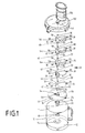
- 10 denotes a container, on the bottom 12 of which a cylindrical neck 14 protruding into the container interior 11 is formed, through the bore 16 of which the end of one from the outside, not shown in the drawing, is formed
- Motor drivable drive shaft 18 extends into the lower container section 154.
- the shaft 18 has a shaft end 20 which is designed as a polygonal pin, for example as a hexagonal pin, on which a shaft coupling 22 can be pushed axially, so that a rotary connection is made between the shaft coupling 22 and the shaft end 20.
- a disk 24 is mounted, which separates the container into an upper and lower container section 152, 154, which is connected to the shaft coupling 22 in a height-displaceable manner via an actuating device 74 and which for Recording various rasping or cutting tools 160, 84, 82 or 80, 28 shown in Fig. 1 is used.
- the friction or cutting tools 160, 84, 82 or 80, 28 have a shaft 30 with an external toothing 32, onto which a holder 36 is pressed or molded, so that a positive connection is made between the shaft 30 and the holder 36.
- a one-piece rasp or knife blade 39, 37, 35 or 38, 34 is fastened to the upper end of the holder 36, for example by integrally molding or riveting the holder 36 onto the blade.
- the blades 39, 37, 35, 38, 34 are essentially crescent-shaped and encircle the shaft 30 in the area 41 in an annular manner and are additionally positively connected to the holder 36 via the annular collar 43.
- the holder 36 has a cylindrical projection 40, which is directed downward in the drawing and has an internal toothing 42 (FIGS.
- the holder 36 is equipped with opposing stop surfaces 50 which are arranged at an angle to one another and extend in the axial direction and which, when the reaming or cutting tool 160, 84, 82 or 80, 28 is inserted, in an axial bore 54 provided in the disk come to rest on corresponding stop surfaces 52 formed in the bore 54 and thus likewise produce a rotationally fixed longitudinal toothing between the reaming or cutting tool 160, 84, 82 or 80, 28 and the disk 24.
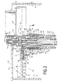
- Stop surfaces 50 are provided with the cutting tools 28, 80 (FIG. 2), a further stop surface 58 with an elongated hole opening 60, into which a pawl 62 of a locking device 64 engages.
- the recess 144 corresponding to the elongated hole opening 60 according to FIG. 2 is dimensioned in its axial length such that the pawl 62 engages without play.
- the lower stop for the pawl 62 is a sheet metal tab 27 which is formed on the inner region 41 of the rasping tool 84 and extends radially outwards. This is omitted in a cutting tool 28 according to FIG. 2.
- the design of the recess 144 is only used in the case of non-adjustable rasping tools 160, 84 and 82.
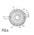
- the locking device 64 is integrated in the carrier disk 24, which consists of a horizontally extending circular plate 68 with an opening 70 and an adjusting device 74.
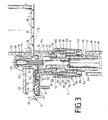
- the blade 39, 37, 35, 38, 34 covers the opening 70 to such an extent that only a small gap 72 between the knife design according to FIG. 2 the blade 34, 38 and the surface 76 of the disk 24 remain, while in the reaming blades 39, 37 and 35 according to FIG. 3, the opening 70 is completely closed and the food only reaches the lower section of the container 10 via the reaming openings 78.
- a cutting tool 80 for producing french fries or other friction or cutting tools 160, 84, 82 can also be mounted on the disk 24.
- a rasp tool 84 is mounted in FIG. 3 on the disk 24, on which the rasp 86 can be clearly recognized. It is important, however, that all the friction or cutting tools 160, 84, 82 or 80, 28 are covered with their holders 36 Lich their connection dimensions are designed so that they can be exchanged for each other depending on the intended use and mounted in the disc 24.
- the disk 24 has on its underside a cylindrical projection 90 which is provided with an internal thread 92, onto which a bush 96 with its external thread 94 can be screwed.
- the bushing 96 is part of the actuating device 74 and serves for the axial displacement of the disk 24 when rotated.
- the actuating device 74 consists of an inner cylinder part 98 and an outer cylinder part 100 arranged at a distance therefrom, so that between the two cylinder parts 98 and 100 Annular space 102 is formed, which serves to receive the cylindrical projection 90 of the disc 24.
- an annular groove 105 running in the cylinder part 100 is provided in the upper region of the adjusting device 74, into which a locking ring 106 can be inserted.
- the two opposite ends of the locking ring 106 have lugs 108 which engage via slot openings 104 formed on the cylinder part 100 in locking grooves 110 provided on the outside of the cylindrical extension 90 of the disk 24 and thus cause a corresponding resistance during the turning process of the adjusting device 74, which a easier and more noticeable adjustment of the cutting height.
- Each locking groove 110 can correspond, for example, to an adjustment step — indicated by marking on the cylinder part 100 and the disk 24. Since the locking ring 106 is resilient, it clamps itself in the two opposite slot openings 104.
- the adjusting device 74 If the adjusting device 74 is rotated, it is adjusted relative to the cylindrical extension 90 in the axial direction of the shaft 30, the two lugs 108 are guided in the locking grooves 110.
- the length of the locking grooves 110 correspond to the maximum adjustment path of the disk 24 and thus the maximum gap width between the cutting tool 28, 80 and the surface 76 of the disk 24.
- a locking ring 114 in the form of an integrally formed annular bead is provided on the inner surface of the bore 113 and engages in an annular groove 116 provided on the shaft coupling 22.
- This provides a stable locking or securing of the actuating device 74 in the axial direction of the drive shaft 18, the actuating device 74 being rotatable relative to the shaft coupling 22.
- the annular space 118 formed at the lower end of the bushing 96 allows the adjusting device 74 to be clipped onto the shaft coupling 22 in an elastic manner. In operation, the adjusting device is supported downward via the annular collar 119 formed on the shaft coupling 22.
- the pawl 62 of the locking device 64 is mounted in FIGS. 2 and 3 in a square slot 120 against the action of a spring 122 adjustable against the bracket 36.
- the elongated hole 120 is located in the circular plate 68 of the disk 24.
- the elongated hole 120 serves to receive the pawl 62 and is covered by a plate 124, so that the pawl 62 can be inserted radially from the inside into the elongated hole 120.
- the upper end of the pin 30 is received in FIGS. 2 and 3 in a bore 130 of a bearing sleeve 131 which is fastened in a recess 133 of a cover 132.
- the cover 132 closes the container 10 from above and secures the shaft 30 against axial displacement between the bearing sleeve 131 and the shaft end 20.
- the adjusting device 74 needs to be rotated and the cylindrical extension 90 of the disk 24 moves out of or into the annular space 102 of the adjusting device 74, depending on the direction of rotation, so that the distance between the cutting tool 28 and the surface 76 of the disk 24 is reduced or enlarged as soon as the arrangement is mounted in the container 10 and closed by the lid 132.
- a scale graduation can be provided on the outer surface of the adjusting device 74, for example, which indicates the exact cutting width accordingly.
- the disk 24 is adjusted until the lower projection 135 of the recess 112 comes into contact with the nose 108 of the locking ring 106.
- an adjustment of the disc is not possible since it is connected to the reaming tool 82, 84, 160 via the pawl 62
- the lid 132 can be firmly connected to the container 10 in FIGS. 2 and 3 via a bayonet device, not shown in the drawing.
- a filling shaft 134 On the upper side of the cover 132 there is a filling shaft 134, via which the material to be shredded can be fed to the grinding or cutting tool 160, 84, 82 or 80, 28 from the outside.
- the cover 132 only has to be removed by loosening the bayonet device by rotating the cover 132 in order to then pull the cutting tool 28 together with the holder 36 off the shaft end coupling 22.
- Another friction or cutting tool 80, 82, 84, 160 can then be inserted into the bore 158 of the shaft coupling 22 from above introduce.
- the lid 132 can again be placed on the container 10 from above, the bore 130 receiving the upper end of the pin 30.
- the ring stage 140 of the shaft coupling 22 is always in contact with the end face of the shaft end 20 of the drive shaft 18 so that the disk 24 can be supported on the shaft coupling 22 via the adjusting device 74.
- the disk 24 is supported on the shaft 30 via the pawl 62 and the holder 36, which always rests on the shaft end 20 of the drive shaft 18. If the adjusting device 74 is rotated when a friction disk 82, 84, 160 is used (FIG. 3), then only the shaft coupling 22 can move up or down depending on the direction of rotation until the lug 108 against the lower or upper projection 135, 138 of the cylindrical approach 90 comes to rest. A further adjustment of the adjusting device 74 is then not possible.
Landscapes
- Engineering & Computer Science (AREA)
- Mechanical Engineering (AREA)
- Life Sciences & Earth Sciences (AREA)
- Forests & Forestry (AREA)
- Food Science & Technology (AREA)
- Food-Manufacturing Devices (AREA)
- Crushing And Pulverization Processes (AREA)
- Knives (AREA)
- Cereal-Derived Products (AREA)
- Formation And Processing Of Food Products (AREA)
Priority Applications (1)
| Application Number | Priority Date | Filing Date | Title |
|---|---|---|---|
| AT88105910T ATE66853T1 (de) | 1987-06-04 | 1988-04-14 | Raspel- oder schneidwerkzeugsanordnung zum zerkleinern von nahrungsmitteln, insbesondere fuer kuechenmaschinen. |
Applications Claiming Priority (2)
| Application Number | Priority Date | Filing Date | Title |
|---|---|---|---|
| DE3718728A DE3718728C1 (de) | 1987-06-04 | 1987-06-04 | Raspel- oder Schneidwerkzeugsanordnung zum Zerkleinern von Nahrungsmitteln,insbesondere fuer Kuechenmaschinen |
| DE3718728 | 1987-06-04 |
Publications (3)
| Publication Number | Publication Date |
|---|---|
| EP0293580A2 true EP0293580A2 (fr) | 1988-12-07 |
| EP0293580A3 EP0293580A3 (en) | 1990-03-14 |
| EP0293580B1 EP0293580B1 (fr) | 1991-09-04 |
Family
ID=6329051
Family Applications (1)
| Application Number | Title | Priority Date | Filing Date |
|---|---|---|---|
| EP88105910A Expired - Lifetime EP0293580B1 (fr) | 1987-06-04 | 1988-04-14 | Machine pour râper ou couper des aliments, en particulier machine de cuisine |
Country Status (6)
| Country | Link |
|---|---|
| US (1) | US4877191A (fr) |
| EP (1) | EP0293580B1 (fr) |
| AT (1) | ATE66853T1 (fr) |
| CA (1) | CA1298533C (fr) |
| DE (2) | DE3718728C1 (fr) |
| ES (1) | ES2029858T3 (fr) |
Cited By (2)
| Publication number | Priority date | Publication date | Assignee | Title |
|---|---|---|---|---|
| EP0409336A1 (fr) * | 1989-07-21 | 1991-01-23 | Koninklijke Philips Electronics N.V. | Dispositif d'appui axial de l'arbre d'entraînement d'un robot ménager |
| WO2018018860A1 (fr) * | 2016-07-26 | 2018-02-01 | 宁波博菱电器有限公司 | Robot ménager destiné à couper des aliments en fils continus et en longs rubans |
Families Citing this family (29)
| Publication number | Priority date | Publication date | Assignee | Title |
|---|---|---|---|---|
| DE9214288U1 (fr) * | 1992-10-22 | 1993-01-14 | Holac Maschinenbau Gmbh, 7920 Heidenheim, De | |
| EP0624335B1 (fr) * | 1993-03-24 | 1995-07-05 | Braun Aktiengesellschaft | Disque à râper pour une machine à multiples fonctions |
| US6004600A (en) * | 1998-10-30 | 1999-12-21 | Van Over; Charles | Method of making bread |
| JP2004510518A (ja) | 2000-10-11 | 2004-04-08 | コーニンクレッカ フィリップス エレクトロニクス エヌ ヴィ | 処理道具に関し軸方向に移動可能なディスクを有する台所器具 |
| US7063283B2 (en) * | 2003-04-25 | 2006-06-20 | Conair Corporation | Enclosure for food processor |
| WO2005018886A1 (fr) * | 2003-08-25 | 2005-03-03 | Brunner Ag | Coupe-legumes |
| JP2007117444A (ja) * | 2005-10-28 | 2007-05-17 | Izumi Products Co | 電動おろし調理器およびおろし金 |
| DE102006042989B4 (de) * | 2006-09-13 | 2014-11-13 | BSH Bosch und Siemens Hausgeräte GmbH | Schneid- oder Raspelscheibe |
| WO2009076585A1 (fr) * | 2007-12-12 | 2009-06-18 | Conair Corporation | Disque éminceur à largeur réglable pour robot culinaire |
| US8943954B2 (en) * | 2008-12-19 | 2015-02-03 | Whirlpool Corporation | Food processor with cleaning tool |
| US8677895B2 (en) * | 2008-12-19 | 2014-03-25 | Whirlpool Corporation | Food processor with dicing element |
| US8051769B2 (en) * | 2008-12-19 | 2011-11-08 | Whirpool Corporation | Food processor with cleaning tool |
| US8671832B2 (en) * | 2009-12-10 | 2014-03-18 | Whirlpool Corporation | Food processor with an external control for adjusting cutting thickness |
| US10449685B2 (en) | 2010-04-29 | 2019-10-22 | Whirlpool Corporation | Food processor with adjustable blade assembly |
| US8720325B2 (en) * | 2010-04-29 | 2014-05-13 | Whirlpool Corporation | Food processor with a lockable adjustable blade assembly |
| US8439285B2 (en) * | 2010-04-29 | 2013-05-14 | Whirlpool Corporation | Adjustable food processor with guide ramp |
| US8985010B2 (en) * | 2010-04-29 | 2015-03-24 | Whirlpool Corporation | Food processor with cutting blade assembly support |
| US9049965B2 (en) | 2011-02-25 | 2015-06-09 | Whirlpool Corporation | Food processing device with an externally operated adjustment mechanism |
| US9655474B2 (en) | 2011-02-25 | 2017-05-23 | Whirlpool Corporation | Food processing device with an externally operated adjustment mechanism |
| US9427111B2 (en) | 2011-02-25 | 2016-08-30 | Whirlpool Corporation | Food processing device with lid mounted controls |
| US8833683B2 (en) | 2012-03-08 | 2014-09-16 | Whirlpool Corporation | Food processor with external control for operating an adjustable cutting tool |
| US8944357B2 (en) | 2012-10-30 | 2015-02-03 | Whirlpool Corporation | Multifunctional food processing tool for use with a food processing device |
| US11224312B2 (en) * | 2013-04-08 | 2022-01-18 | Conair Llc | Food processor having external slicing disc adjustment |
| DE102013217688A1 (de) * | 2013-09-04 | 2015-03-05 | BSH Bosch und Siemens Hausgeräte GmbH | Komponente und Werkzeug eines Küchengeräts |
| CN203619410U (zh) * | 2013-11-28 | 2014-06-04 | 广东德豪润达电气股份有限公司 | 具有切丝/片功能的食物加工机 |
| CN204248975U (zh) * | 2014-12-04 | 2015-04-08 | 惠阳亚伦塑胶电器实业有限公司 | 一种切丁机 |
| US20180289218A1 (en) | 2015-10-20 | 2018-10-11 | Spectrum Brands, Inc. | Oscillating blade food processor with cutting accessories |
| US10695935B2 (en) | 2016-08-11 | 2020-06-30 | Conair Corporation | Slicing disc assembly for food processor |
| US11325274B1 (en) | 2020-12-09 | 2022-05-10 | Conair Llc | Food slicing disc with adjustable vertical and horizontal blades |
Citations (3)
| Publication number | Priority date | Publication date | Assignee | Title |
|---|---|---|---|---|
| US4113188A (en) * | 1977-04-25 | 1978-09-12 | Kidde Consumer Durables Corp. | Food processor |
| DE3020242A1 (de) * | 1980-05-28 | 1981-12-10 | Breville Holdings Pty. Ltd., Pyrmont, Neusüdwales | Schnitzelmesseranordnung enthaltend ein drehbares schnitzelmesser fuer ein nahrungsmittelbearbeitungsgeraet |
| FR2582497A1 (fr) * | 1985-05-31 | 1986-12-05 | Coggiola Marcel | Dispositif de coupe pour robot de cuisine |
Family Cites Families (3)
| Publication number | Priority date | Publication date | Assignee | Title |
|---|---|---|---|---|
| GB2076638B (en) * | 1980-05-21 | 1984-02-01 | Breville Holdings Pty Ltd | A rotatable cutting blade assembly |
| IT1152315B (it) * | 1982-08-03 | 1986-12-31 | Alfredo Cavalli | Apparecchio multiuso per tritare,affettare o tagliare a tocchetti o bastoncini verdure e prodotti alimentari |
| US4560111A (en) * | 1984-01-04 | 1985-12-24 | Alfredo Cavalli | Electric household appliance for cutting fruit, vegetables and similar food products into small sticks or chunks of variable thickness |
-
1987
- 1987-06-04 DE DE3718728A patent/DE3718728C1/de not_active Expired
-
1988
- 1988-04-14 EP EP88105910A patent/EP0293580B1/fr not_active Expired - Lifetime
- 1988-04-14 AT AT88105910T patent/ATE66853T1/de not_active IP Right Cessation
- 1988-04-14 ES ES198888105910T patent/ES2029858T3/es not_active Expired - Lifetime
- 1988-04-14 DE DE8888105910T patent/DE3864586D1/de not_active Expired - Fee Related
- 1988-05-18 CA CA000567133A patent/CA1298533C/fr not_active Expired - Fee Related
- 1988-05-25 US US07/198,788 patent/US4877191A/en not_active Expired - Fee Related
Patent Citations (3)
| Publication number | Priority date | Publication date | Assignee | Title |
|---|---|---|---|---|
| US4113188A (en) * | 1977-04-25 | 1978-09-12 | Kidde Consumer Durables Corp. | Food processor |
| DE3020242A1 (de) * | 1980-05-28 | 1981-12-10 | Breville Holdings Pty. Ltd., Pyrmont, Neusüdwales | Schnitzelmesseranordnung enthaltend ein drehbares schnitzelmesser fuer ein nahrungsmittelbearbeitungsgeraet |
| FR2582497A1 (fr) * | 1985-05-31 | 1986-12-05 | Coggiola Marcel | Dispositif de coupe pour robot de cuisine |
Cited By (2)
| Publication number | Priority date | Publication date | Assignee | Title |
|---|---|---|---|---|
| EP0409336A1 (fr) * | 1989-07-21 | 1991-01-23 | Koninklijke Philips Electronics N.V. | Dispositif d'appui axial de l'arbre d'entraînement d'un robot ménager |
| WO2018018860A1 (fr) * | 2016-07-26 | 2018-02-01 | 宁波博菱电器有限公司 | Robot ménager destiné à couper des aliments en fils continus et en longs rubans |
Also Published As
| Publication number | Publication date |
|---|---|
| ATE66853T1 (de) | 1991-09-15 |
| EP0293580B1 (fr) | 1991-09-04 |
| EP0293580A3 (en) | 1990-03-14 |
| US4877191A (en) | 1989-10-31 |
| DE3718728C1 (de) | 1988-07-28 |
| DE3864586D1 (de) | 1991-10-10 |
| CA1298533C (fr) | 1992-04-07 |
| ES2029858T3 (es) | 1992-10-01 |
Similar Documents
| Publication | Publication Date | Title |
|---|---|---|
| EP0293580B1 (fr) | Machine pour râper ou couper des aliments, en particulier machine de cuisine | |
| DE19520618C2 (de) | Messerhalterung für Kreiselmäher | |
| DE102006047480B4 (de) | Kugelmühle mit Mitnahmemitteln für eine formschlüssige Verbindung zwischen Mahlgefäß und Aufnahmevorrichtung | |
| DE4113641A1 (de) | Handwerkzeugmaschine | |
| DE102006005572B4 (de) | Stanzvorrichtung | |
| DE102006025137B4 (de) | Schneidwerkzeuge und Führungseinrichtung | |
| EP0585607B1 (fr) | Machine à café express | |
| DE3644267A1 (de) | Schneideinsatz fuer einen arbeitsbehaelter einer kuechenmaschine | |
| DE3627276A1 (de) | Schneideinsatz fuer einen arbeitsbehaelter einer kuechenmaschine | |
| DE10317319A1 (de) | Schneidemaschine für Lebensmittel | |
| EP1340574A2 (fr) | Machine à fraiser à main | |
| DE3341206C2 (fr) | ||
| EP2944441B1 (fr) | Trancheuse mandoline | |
| DE3735912A1 (de) | Nachgiebig befestigter veraenderbarer widerstand | |
| EP0115853B1 (fr) | Disque pour faucheuse à disques rotatifs | |
| DE3220449A1 (de) | Kuechenmaschine mit motorischem antrieb | |
| EP0842627B1 (fr) | Outil à mélanger, pétrir ou couper pour un appareil de cuisine | |
| DE2525776B2 (fr) | ||
| EP0363864B1 (fr) | Grignoteuse guidée par la main | |
| DE3341180C2 (de) | Haushaltsschneidemaschine, insbesondere mit elektromotorischem Antrieb | |
| DE3446656C2 (fr) | ||
| WO2014009460A1 (fr) | Rape circulaire | |
| DE3146637A1 (de) | Vielzweck-kuechenmaschine mit motorischem antrieb | |
| DE1119145B (de) | Maschine zum Zerkleinern, Mischen und Umruehren von Lebensmitteln, insbesondere Fleisch | |
| EP4076114A1 (fr) | Broyeur, disque de broyage pour un broyeur et machine à café équipée d'un tel broyeur |
Legal Events
| Date | Code | Title | Description |
|---|---|---|---|
| PUAI | Public reference made under article 153(3) epc to a published international application that has entered the european phase |
Free format text: ORIGINAL CODE: 0009012 |
|
| AK | Designated contracting states |
Kind code of ref document: A2 Designated state(s): AT CH DE ES FR GB IT LI NL |
|
| PUAL | Search report despatched |
Free format text: ORIGINAL CODE: 0009013 |
|
| AK | Designated contracting states |
Kind code of ref document: A3 Designated state(s): AT CH DE ES FR GB IT LI NL |
|
| 17P | Request for examination filed |
Effective date: 19900421 |
|
| 17Q | First examination report despatched |
Effective date: 19910207 |
|
| ITF | It: translation for a ep patent filed |
Owner name: DE DOMINICIS & MAYER S.R.L. |
|
| GRAA | (expected) grant |
Free format text: ORIGINAL CODE: 0009210 |
|
| AK | Designated contracting states |
Kind code of ref document: B1 Designated state(s): AT CH DE ES FR GB IT LI NL |
|
| REF | Corresponds to: |
Ref document number: 66853 Country of ref document: AT Date of ref document: 19910915 Kind code of ref document: T |
|
| REF | Corresponds to: |
Ref document number: 3864586 Country of ref document: DE Date of ref document: 19911010 |
|
| GBT | Gb: translation of ep patent filed (gb section 77(6)(a)/1977) | ||
| ET | Fr: translation filed | ||
| PLBE | No opposition filed within time limit |
Free format text: ORIGINAL CODE: 0009261 |
|
| STAA | Information on the status of an ep patent application or granted ep patent |
Free format text: STATUS: NO OPPOSITION FILED WITHIN TIME LIMIT |
|
| 26N | No opposition filed | ||
| REG | Reference to a national code |
Ref country code: ES Ref legal event code: FG2A Ref document number: 2029858 Country of ref document: ES Kind code of ref document: T3 |
|
| PGFP | Annual fee paid to national office [announced via postgrant information from national office to epo] |
Ref country code: ES Payment date: 19950417 Year of fee payment: 8 |
|
| PGFP | Annual fee paid to national office [announced via postgrant information from national office to epo] |
Ref country code: CH Payment date: 19950526 Year of fee payment: 8 |
|
| PGFP | Annual fee paid to national office [announced via postgrant information from national office to epo] |
Ref country code: GB Payment date: 19960325 Year of fee payment: 9 |
|
| PGFP | Annual fee paid to national office [announced via postgrant information from national office to epo] |
Ref country code: AT Payment date: 19960411 Year of fee payment: 9 |
|
| PG25 | Lapsed in a contracting state [announced via postgrant information from national office to epo] |
Ref country code: ES Free format text: LAPSE BECAUSE OF NON-PAYMENT OF DUE FEES Effective date: 19960415 |
|
| PG25 | Lapsed in a contracting state [announced via postgrant information from national office to epo] |
Ref country code: LI Effective date: 19960430 Ref country code: CH Effective date: 19960430 |
|
| REG | Reference to a national code |
Ref country code: CH Ref legal event code: PL |
|
| PG25 | Lapsed in a contracting state [announced via postgrant information from national office to epo] |
Ref country code: GB Effective date: 19970414 Ref country code: AT Effective date: 19970414 |
|
| PGFP | Annual fee paid to national office [announced via postgrant information from national office to epo] |
Ref country code: FR Payment date: 19970416 Year of fee payment: 10 |
|
| PGFP | Annual fee paid to national office [announced via postgrant information from national office to epo] |
Ref country code: NL Payment date: 19970428 Year of fee payment: 10 |
|
| GBPC | Gb: european patent ceased through non-payment of renewal fee |
Effective date: 19970414 |
|
| PG25 | Lapsed in a contracting state [announced via postgrant information from national office to epo] |
Ref country code: FR Free format text: THE PATENT HAS BEEN ANNULLED BY A DECISION OF A NATIONAL AUTHORITY Effective date: 19980430 |
|
| PG25 | Lapsed in a contracting state [announced via postgrant information from national office to epo] |
Ref country code: NL Free format text: LAPSE BECAUSE OF NON-PAYMENT OF DUE FEES Effective date: 19981101 |
|
| NLV4 | Nl: lapsed or anulled due to non-payment of the annual fee |
Effective date: 19981101 |
|
| REG | Reference to a national code |
Ref country code: FR Ref legal event code: ST |
|
| REG | Reference to a national code |
Ref country code: ES Ref legal event code: FD2A Effective date: 19990201 |
|
| PGFP | Annual fee paid to national office [announced via postgrant information from national office to epo] |
Ref country code: DE Payment date: 20020412 Year of fee payment: 15 |
|
| PG25 | Lapsed in a contracting state [announced via postgrant information from national office to epo] |
Ref country code: DE Free format text: LAPSE BECAUSE OF NON-PAYMENT OF DUE FEES Effective date: 20031101 |
|
| PG25 | Lapsed in a contracting state [announced via postgrant information from national office to epo] |
Ref country code: IT Free format text: LAPSE BECAUSE OF NON-PAYMENT OF DUE FEES;WARNING: LAPSES OF ITALIAN PATENTS WITH EFFECTIVE DATE BEFORE 2007 MAY HAVE OCCURRED AT ANY TIME BEFORE 2007. THE CORRECT EFFECTIVE DATE MAY BE DIFFERENT FROM THE ONE RECORDED. Effective date: 20050414 |