EP0293082B1 - Actuator - Google Patents
Actuator Download PDFInfo
- Publication number
- EP0293082B1 EP0293082B1 EP88303748A EP88303748A EP0293082B1 EP 0293082 B1 EP0293082 B1 EP 0293082B1 EP 88303748 A EP88303748 A EP 88303748A EP 88303748 A EP88303748 A EP 88303748A EP 0293082 B1 EP0293082 B1 EP 0293082B1
- Authority
- EP
- European Patent Office
- Prior art keywords
- piston
- actuator according
- orifice
- actuator
- head
- Prior art date
- Legal status (The legal status is an assumption and is not a legal conclusion. Google has not performed a legal analysis and makes no representation as to the accuracy of the status listed.)
- Expired - Lifetime
Links
- 239000012530 fluid Substances 0.000 claims abstract description 23
- 230000006835 compression Effects 0.000 claims description 6
- 238000007906 compression Methods 0.000 claims description 6
- 239000000463 material Substances 0.000 claims description 4
- 239000004033 plastic Substances 0.000 claims description 4
- 229920003023 plastic Polymers 0.000 claims description 4
- 239000013536 elastomeric material Substances 0.000 claims description 2
- 238000007789 sealing Methods 0.000 description 3
- 238000010276 construction Methods 0.000 description 2
- 244000273618 Sphenoclea zeylanica Species 0.000 description 1
- 230000004323 axial length Effects 0.000 description 1
- 230000000994 depressogenic effect Effects 0.000 description 1
- 238000009434 installation Methods 0.000 description 1
- 238000004519 manufacturing process Methods 0.000 description 1
- 230000000717 retained effect Effects 0.000 description 1
Images

Classifications
-
- G—PHYSICS
- G05—CONTROLLING; REGULATING
- G05G—CONTROL DEVICES OR SYSTEMS INSOFAR AS CHARACTERISED BY MECHANICAL FEATURES ONLY
- G05G1/00—Controlling members, e.g. knobs or handles; Assemblies or arrangements thereof; Indicating position of controlling members
- G05G1/30—Controlling members actuated by foot
- G05G1/46—Means, e.g. links, for connecting the pedal to the controlled unit
-
- B—PERFORMING OPERATIONS; TRANSPORTING
- B60—VEHICLES IN GENERAL
- B60T—VEHICLE BRAKE CONTROL SYSTEMS OR PARTS THEREOF; BRAKE CONTROL SYSTEMS OR PARTS THEREOF, IN GENERAL; ARRANGEMENT OF BRAKING ELEMENTS ON VEHICLES IN GENERAL; PORTABLE DEVICES FOR PREVENTING UNWANTED MOVEMENT OF VEHICLES; VEHICLE MODIFICATIONS TO FACILITATE COOLING OF BRAKES
- B60T11/00—Transmitting braking action from initiating means to ultimate brake actuator without power assistance or drive or where such assistance or drive is irrelevant
- B60T11/10—Transmitting braking action from initiating means to ultimate brake actuator without power assistance or drive or where such assistance or drive is irrelevant transmitting by fluid means, e.g. hydraulic
- B60T11/16—Master control, e.g. master cylinders
- B60T11/22—Master control, e.g. master cylinders characterised by being integral with reservoir
-
- B—PERFORMING OPERATIONS; TRANSPORTING
- B60—VEHICLES IN GENERAL
- B60T—VEHICLE BRAKE CONTROL SYSTEMS OR PARTS THEREOF; BRAKE CONTROL SYSTEMS OR PARTS THEREOF, IN GENERAL; ARRANGEMENT OF BRAKING ELEMENTS ON VEHICLES IN GENERAL; PORTABLE DEVICES FOR PREVENTING UNWANTED MOVEMENT OF VEHICLES; VEHICLE MODIFICATIONS TO FACILITATE COOLING OF BRAKES
- B60T7/00—Brake-action initiating means
- B60T7/02—Brake-action initiating means for personal initiation
- B60T7/04—Brake-action initiating means for personal initiation foot actuated
-
- F—MECHANICAL ENGINEERING; LIGHTING; HEATING; WEAPONS; BLASTING
- F16—ENGINEERING ELEMENTS AND UNITS; GENERAL MEASURES FOR PRODUCING AND MAINTAINING EFFECTIVE FUNCTIONING OF MACHINES OR INSTALLATIONS; THERMAL INSULATION IN GENERAL
- F16D—COUPLINGS FOR TRANSMITTING ROTATION; CLUTCHES; BRAKES
- F16D25/00—Fluid-actuated clutches
- F16D25/12—Details not specific to one of the before-mentioned types
-
- G—PHYSICS
- G05—CONTROLLING; REGULATING
- G05G—CONTROL DEVICES OR SYSTEMS INSOFAR AS CHARACTERISED BY MECHANICAL FEATURES ONLY
- G05G1/00—Controlling members, e.g. knobs or handles; Assemblies or arrangements thereof; Indicating position of controlling members
- G05G1/30—Controlling members actuated by foot
Definitions
- This invention relates to actuators for fluid pressure systems.
- An example system to which the invention is applicable is a hydraulically operated clutch system, but the invention has other applications including hydraulic brake systems.
- Hydraulic clutch systems typically include a master cylinder which is operated to generate the primary driving force and therefore functions as the system actuator, and a slave cylinder which responds to that force so as to cause operation of the clutch.
- a foot pedal is generally used as the device through which operation of the master cylinder is achieved.
- a reservoir containing a supply of hydraulic fluid is connected into the system, usually to the master cylinder, so as to make up for fluid losses which may occur over a period of time.
- US-A-2525740 which is considered to be the most relevant prior art, discloses an actuator assembly comprising a cylinder and a piston, whereby the reservoir is separated from the pressure chamber by transversal wall, formed across the cylinder bore.
- This actuator assembly has some of the broad features of the present invention, but it differs in numerous ways which render it less compact and easy to assemble/disassemble, and which require additional, extraneous, components.
- An object of the present invention is to provide a simple and yet effective actuator for a fluid pressure system.
- it is an object of the invention to provide an improved master cylinder for use in a hydraulic fluid system, such as a clutch or brake system.
- a fluid pressure actuator comprising: a body having a cylindrical bore therein; a piston having a head portion slidably mounted in the bore and a stem which projects out of the body through one end thereof; a pressure chamber having a first part formed within the body between the head portion of the piston and an end wall of the body at the end thereof remote from the stem, and a second part formed by a passage within the piston; a fluid reservoir separated from the pressure chamber by a transverse wall formed across the passage at an end of the passage remote from the head end of the piston; orifice means connecting the interior of the fluid reservoir with the passage, through the transverse wall; a valve closure member provided in the passage, operable to close the orifice means in response to movement of the piston towards the end wall; a tie operable to cause the valve closure member to lift off the orifice when the piston moves to a rest position remote from the end wall of the body; a compression spring acting between the piston and the end wall and biasing the piston into the rest position; and, stop means
- the actuator may be utilized with a foot pedal to provide a pedal actuator suitable for use as a brake or clutch pedal or like applications.
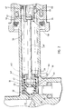
- the actuator 1 shown in Figure 1 comprises a master cylinder 2 which is composed wholly or substantially of plastics material. Different plastics materials may be selected for different components of the actuator according to the respective use conditions of those components.
- the body of the acutator shown is in the form of a tubular member or cylinder 3 which is open at one end 4 and closed at the other end 5 by an end wall 6.
- a mounting flange 7 projects outwardly from that end wall 6 for a reason hereinafter made clear.
- the interior of the cylinder 3 is defined by a cylindrical bore 8 which is preferably of constant diameter over at least a substantial part of its length.
- a piston 9 is slidably mounted in the cylinder bore 8 and is connected to a stem 10 which projects axially out of the cylinder 3 through the open end thereof.
- the piston 9 and the stem 10 are integrally formed from a suitable plastics material.
- Sealing means are provided on the piston 9 for sealing sliding engagement with the surface of the surrounding bore 8.
- this sealing means comprises a pair of O-ring seals 11.
- Any suitable stop means 12 may be provided at or adjacent the open end 4 of the cylinder 3 to restrain the piston 9 against movement through that open end 4.
- the stem 10 has a diameter less than that of the piston 9.
- Biasing means such as a coil compression spring 13 acts between the piston 9 and the body end wall 6 so as normally to urge the piston 9 towards a rest position at which it is adjacent the body open end 4 and engages the stop means 12 secured to the cylinder 3.
- the part of the cylinder bore 8 between the piston 9 and the body end wall 6 forms a portion of a pressure chamber 14.
- another portion of that chamber 14 is formed by an axial bore 15 formed in the piston 9 and extending into the associated stem 10. That bore 15 extends through the piston end adjacent the cylinder end wall 6.
- the pressure chamber 14 is connected to an outlet line 16 through an outlet port 17 provided through a side wall 18 of the piston stem 10, at a location remote from the end of the stem 10 which is connected to the piston 9.
- a fluid supply reservoir 19 is connected to the hollow stem 10 rather than direct to the cylinder body 3 as in prior actuators.
- That reservoir 19 includes a hollow body 20 which may be formed integrally with the end of the stem 10 which is remote from the piston 9.
- a transverse wall 21 separates the interior of the reservoir 19 from the stem bore 15 and an orifice 22 is provided through that wall 21 to permit transfer of fluid between the reservoir 19 and the pressure chamber 14. Fluid may be introduced into the reservoir 19 through an access opening positioned remote from the piston stem 10, and a removable closure 24 is provided over that opening.
- Valve means 25 shown in detail in Figure 2, is associated with the orifice 22 and is operable to close that orifice 22 when the actuator 1 is being operated to cause the piston 9 to move towards the end wall 6 of the cylinder body 3. It is preferred that the valve means 25 is retained in an orifice open position when the piston 9 is at its rest position so that fluid can pass from the reservoir 19 to the pressure chamber 14 in order to make up for any losses occurring during operation of the actuator.
- the valve means 25 includes a closure element 26 which is located within the piston stem bore 15 and includes a head portion 27 arranged to engage a annular valve seat 28 extending around the orifice 22. That valve seat 28 is depicted as having a frusto-conical form, but that is not essential.
- the head portion 27 includes a part-spherical section 29 which forms a terminal extremity of the closure element 26 and which is connected to a circular flange 30 or boss through a neck 31 of reduced diameter.
- a flexible cap 32 of rubber or other suitable elastomeric material is snap-engaged over that part-spherical section 29 so as to form the valve seat engaging surface of the closure element 26.
- any suitable retaining means may be provided to retain the closure element 26 in an orifice open position when the piston 9 is at its rest position.
- that retaining means 33 includes a tubular member 34 which is held against or secured to the end wall 6 of the cylinder body 3, and a rod 35 which connects the head portion 27 to that tubular member 34.
- the rod 35 may be formed integrally with the head portion 27 and extends axially from that head portion 27 towards the cylinder body end wall 6.
- the tubular member 34 extends axially from that end wall 6 towards the cylinder open end 4 and in the arrangement shown projects into the piston bore 15 with clearance.
- connection between the rod 35 and the tubular member 34 is such as to permit limited relative axial movement between those components.
- the rod 35 extends through an opening 36 in the adjacent end of the tubular member 34 and is slidable within that opening 36 to permit relative axial movement between the rod 35 and tubular member 34.
- the end portion of the rod 35 located within the tubular member 34 is provided with an enlargement 37 which is engageable with a transverse abutment surface 38 of the tubular member 34.
- the enlargement 37 and abutment surface 38 engage when the piston 9 is in its rest position and thereby hold the head portion 27 clear of the valve seat 28 so that fluid can pass between the reservoir 19 and the pressure chamber 14.
- the tubular member 34 may be held against the cylinder end wall 6 by means of the biasing spring 13, and in that event may have a laterally projecting flange 39 at its terminal end to provide a surface against which the spring 13 can engage. Any suitable means may be provided to permit fluid to pass between the interior of the tubular member 34 and the portionof the pressure chamber 14 surrounding it.
- one or more longitudinally extending slots 40 are formed through the side wall of the tubular member 34.
- Guide means 41 is preferably provided within the piston stem bore 15 to ensure that the head portion 27 of the closure element 26 is correctly aligned with the valve seat 28.
- That guide means 41 may include a sleeve 42 positioned within the end of the stem bore 15 adjacent the reservoir 19 and which slidably contains the head portion 27.
- the guide sleeve 42 also functions as a stop which limits the degree of movement of the head portion 27 away from the valve seat 28.
- Opposed surfaces of the sleeve 42 and head portion 27 engage when the head portion 27 and valve seat 28 are separated to an extent sufficient to permit adequate fluid transfer between the reservoir 19 and the pressure chamber 14.
- a coil compression spring 43 acts between the guide sleeve 42 and the tubular member 34 so as to hold the sleeve 42 resiliently against the transverse wall 21. That spring 43 allows the sleeve 42 to move away from the transverse wall 21 in the event that axial expansion of the actuator 1 exceeds that at which the stop 12 becomes operative.
- the head portion 27 of the closure element 26 is urged against the valve seat 28 by pressure of the fluid within the pressure chamber 14.
- adequate clearance is provided between the closure member rod 35 and the guide sleeve 42 to permit fluid within the stem bore 42 to impinge against the head portion 27.
- a suitable spring 44 acts between the guide sleeve 42 and the head portion 27 to augment that valve closing influence.
- the outlet port 17 is located in a portion of the stem side wall 18 which surrounds the guide sleeve 42.
- Appropriate access passage means 45 may be provided in that sleeve 42 or side wall 18 to ensure proper communication between the outlet port 17 and the pressure chamber 14.
- the end portion 46 of the tubular member 34 adjacent the valve seat 28 is of reduced diameter to provide a shoulder 47 against which the spring 43 acting on the guide sleeve 42 can engage.
- One or more openings 48 may be provided through the side wall of that end portion 46 to ensure proper communication between the stem bore 15 and the interior of the tubular member 34.
- An actuator 1 as described has important advantages over prior actuators. It is of particularly simple and compact construction, and factors which contribute to that result are the hollow piston stem 10 and the connection of the reservoir 19 to that stem 10 rather than directly to the cylinder body 3. Another advantage arises from the particular valve means described. That valve means provides for only one possible leakage path between the reservoir 19 and the pressure chamber 14, whereas two or more such paths generally exist in prior arrangements.
- the actuator 1 of the invention is adapted to be included in a simple and effective actuator assembly.
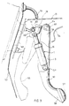
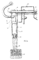
- the assembly depicted in Figures 3 and 4 of the drawings includes a foot pedal 50 which is arranged to cause operation of the actuator 1.
- the actuator 1 and the foot pedal 50 are each connected to a common mounting bracket 51 which is adapted to be secured to a vehicle fire wall 52, for example.
- the bracket 51 in one form has a base 53 and a pair of side walls 54 upstanding from that base.
- the foot pedal 50 and the actuator 1 are located between those side walls 54 and each is independently pivotally connected to the bracket 51 for movement towards and away from the bracket base 53.
- the foot pedal 50 and actuator 1 are also pivotally connected to one another and the arrangement is such that pivotal movement of the foot pedal 50 causes reduction in the axial length of the actuator 1 and thereby operates the actuator 1.
- the depressed position of the foot pedal 50 is depicted in Figure 3 by dotted lines 55.
- the pedal 50 has one end 56 pivotally connected to the bracket 51 and has a foot engaging pad 57 at its opposite end 58.
- the body 3 of the actuator 1 is pivotally connected to the foot pedal 50 through the mounting flange 7, and that connection is at a location between the ends 56 and 58 of the pedal 60.
- the pedal 50 is of channel shape between its end and the actuator body 3 is at least partially located within that channel under all circumstances of use.
- the axis 59 of the pivotal connection between the actuator and pedal is substantially parallel to the axis 60 of the pivot about which the pedal 50 moves.
- a mounting flange 61 is provided at the end of the piston stem 10 remote from the actuator body 3 and that flange 61 is used to connect the stem 10 pivotally to the mounting bracket 51.
- the pivot axis 62 is substantially parallel to the pivot axis 60 of the pedal.
- pedal 50 and actuator 1 need not be connected to a bracket 51 as described. Furthermore, each may be independently connected to a support structure rather than through a common bracket.
- An assembly as described is extremely compact and has the advantage of placing the actuator 1 under compression when in use. There is the further advantage of having the reservoir 19 located in direct association with the actuator 1 rather than being remote therefrom.
- an actuator for a fluid pressure system including a foot pedal pivotally connected to a support structure for movement away from and into a rest position; a piston-cylinder assembly having a piston slidably mounted within a bore of a cylinder member and a pressure chamber formed at least in part within said member, movement of said piston in one direction relative to said member being operable to cause a reduction in the volumetric size of said chamber, said assembly being pivotally connected to the foot pedal and the support structure respectively, characterized in that the pivotal connection to the foot pedal is located intermediate the ends of a lever forming part of the foot pedal, and that the two said pivotable connections with the support structure are spaced apart so that movement of said pedal away from said rest position causes movement of said piston in said one direction.
Landscapes
- Engineering & Computer Science (AREA)
- Mechanical Engineering (AREA)
- Transportation (AREA)
- General Engineering & Computer Science (AREA)
- General Physics & Mathematics (AREA)
- Automation & Control Theory (AREA)
- Physics & Mathematics (AREA)
- Hydraulic Clutches, Magnetic Clutches, Fluid Clutches, And Fluid Joints (AREA)
- Mechanical Control Devices (AREA)
- Actuator (AREA)
- Arrangement And Mounting Of Devices That Control Transmission Of Motive Force (AREA)
- Transmission Of Braking Force In Braking Systems (AREA)
- Valve Device For Special Equipments (AREA)
- Fluid-Driven Valves (AREA)
- Reciprocating, Oscillating Or Vibrating Motors (AREA)
Priority Applications (1)
| Application Number | Priority Date | Filing Date | Title |
|---|---|---|---|
| AT88303748T ATE86566T1 (de) | 1987-05-28 | 1988-04-26 | Stellglied. |
Applications Claiming Priority (2)
| Application Number | Priority Date | Filing Date | Title |
|---|---|---|---|
| AU2193/87 | 1987-05-28 | ||
| AUPI219387 | 1987-05-28 |
Related Child Applications (1)
| Application Number | Title | Priority Date | Filing Date |
|---|---|---|---|
| EP91308032.1 Division-Into | 1988-04-26 |
Publications (3)
| Publication Number | Publication Date |
|---|---|
| EP0293082A2 EP0293082A2 (en) | 1988-11-30 |
| EP0293082A3 EP0293082A3 (en) | 1989-10-18 |
| EP0293082B1 true EP0293082B1 (en) | 1993-03-10 |
Family
ID=3772202
Family Applications (2)
| Application Number | Title | Priority Date | Filing Date |
|---|---|---|---|
| EP88303748A Expired - Lifetime EP0293082B1 (en) | 1987-05-28 | 1988-04-26 | Actuator |
| EP91308032A Withdrawn EP0462848A2 (en) | 1987-05-28 | 1988-04-26 | Fluid pressure actuator |
Family Applications After (1)
| Application Number | Title | Priority Date | Filing Date |
|---|---|---|---|
| EP91308032A Withdrawn EP0462848A2 (en) | 1987-05-28 | 1988-04-26 | Fluid pressure actuator |
Country Status (6)
| Country | Link |
|---|---|
| US (1) | US4910962A (enExample) |
| EP (2) | EP0293082B1 (enExample) |
| JP (1) | JPS63297825A (enExample) |
| KR (1) | KR880013753A (enExample) |
| AT (1) | ATE86566T1 (enExample) |
| DE (1) | DE3878984D1 (enExample) |
Families Citing this family (14)
| Publication number | Priority date | Publication date | Assignee | Title |
|---|---|---|---|---|
| GB8810553D0 (en) * | 1988-05-05 | 1988-06-08 | Smith D W | Integrated hydraulic pedal |
| DE3932529C2 (de) * | 1989-09-29 | 1997-12-04 | Teves Gmbh Alfred | Betätigungseinrichtung für eine hydraulische Brems- oder Kupplungsanlage |
| GB2266577A (en) * | 1992-04-21 | 1993-11-03 | Ford Motor Co | Pedal assembly incorporating a hydraulic cylinder. |
| DE4301229C1 (de) * | 1993-01-19 | 1993-12-16 | Daimler Benz Ag | Betätigungseinrichtung für eine Kupplungs- oder Bremsanlage eines Fahrzeuges |
| FR2775459B1 (fr) | 1998-02-27 | 2000-04-21 | Bosch Syst Freinage | Dispositif hydro-mecanique de transmission d'effort |
| BR9905185A (pt) | 1999-09-10 | 2001-04-24 | Volkswagen Do Brasil Ltda Oper | Sistema de redução de esforço de acionamento de pedal de embreagem para veìculo automotores |
| DE10063595B4 (de) * | 2000-12-20 | 2010-12-02 | Volkswagen Ag | Pedalwerk für ein Fahrzeug |
| US20060071550A1 (en) * | 2004-10-05 | 2006-04-06 | Buckley James A | Hydraulic actuator having an integrated pedal and pressure vessel assembly |
| DE102015111581A1 (de) * | 2015-07-16 | 2017-01-19 | Gustav Magenwirth Gmbh & Co. Kg | Gebereinheit |
| JP6825394B2 (ja) * | 2017-02-01 | 2021-02-03 | スズキ株式会社 | 自動二輪車の後輪ブレーキ用マスターシリンダ装置及び自動二輪車の後輪ブレーキ用マスターシリンダ配置方法 |
| US11046176B2 (en) | 2017-03-21 | 2021-06-29 | Arctic Cat Inc. | Off-road utility vehicle |
| US10717474B2 (en) | 2017-03-21 | 2020-07-21 | Arctic Cat Inc. | Cab and fasteners for vehicle cab |
| US11014419B2 (en) | 2017-03-21 | 2021-05-25 | Arctic Cat Inc. | Off-road utility vehicle |
| KR102337223B1 (ko) * | 2017-07-13 | 2021-12-08 | 현대자동차주식회사 | 차량용 페달 장치 |
Family Cites Families (14)
| Publication number | Priority date | Publication date | Assignee | Title |
|---|---|---|---|---|
| DE558038C (de) * | 1932-08-31 | Edward Bishop Boughton | Bremszylinder fuer Fluessigkeitsbremsen von Kraftfahrzeugen | |
| US2148273A (en) * | 1935-07-29 | 1939-02-21 | Bendix Prod Corp | Hydraulic brake operating means |
| US2239673A (en) * | 1938-06-06 | 1941-04-29 | Hydraulic Brake Co | Fluid pressure braking system |
| US2284935A (en) * | 1939-06-29 | 1942-06-02 | Bendix Aviat Corp | Master cylinder |
| US2377017A (en) * | 1941-12-27 | 1945-05-29 | Jr Ralph D Lacoe | Master cylinder |
| US2525740A (en) * | 1946-11-19 | 1950-10-10 | Dunlop Rubber Co | Master cylinder |
| DE1243541B (de) * | 1962-01-26 | 1967-06-29 | Teves Kg Alfred | Stufenhauptzylinder, insbesondere fuer die Bremsen von Kraftfahrzeugen |
| FR86139E (fr) * | 1964-07-10 | 1965-12-17 | Ferodo Sa | Procédé et dispositif de commande de débrayage |
| DE3219134A1 (de) * | 1982-05-21 | 1983-11-24 | Teves Gmbh Alfred | Hauptzylinder fuer hydraulisch betaetigte kraftfahrzeugbremsen |
| JPS6130725U (ja) * | 1984-07-27 | 1986-02-24 | アイシン精機株式会社 | 可変バルブリフト型クラツチマスタシリンダ |
| DE3444829A1 (de) * | 1984-12-08 | 1986-06-12 | Robert Bosch Gmbh, 7000 Stuttgart | Bremskraftverstaerker |
| JPS61146662A (ja) * | 1984-12-19 | 1986-07-04 | Nippon Air Brake Co Ltd | マスタシリンダ |
| US4753075A (en) * | 1985-10-18 | 1988-06-28 | Toyota Jidosha Kabushiki Kaisha | Portless type master cylinder device with intake valve and flow resisting means between pressure chamber and reservoir chamber |
| US4773224A (en) * | 1985-10-18 | 1988-09-27 | Toyota Jidosha Kabushiki Kaisha | Portless type master cylinder device with non return valve and restricted passage in parallel between pressure chamber and fluid reservoir |
-
1988
- 1988-04-04 US US07/177,418 patent/US4910962A/en not_active Expired - Lifetime
- 1988-04-26 EP EP88303748A patent/EP0293082B1/en not_active Expired - Lifetime
- 1988-04-26 DE DE8888303748T patent/DE3878984D1/de not_active Expired - Lifetime
- 1988-04-26 AT AT88303748T patent/ATE86566T1/de not_active IP Right Cessation
- 1988-04-26 EP EP91308032A patent/EP0462848A2/en not_active Withdrawn
- 1988-05-09 JP JP63112296A patent/JPS63297825A/ja active Pending
- 1988-05-27 KR KR1019880006271A patent/KR880013753A/ko not_active Withdrawn
Also Published As
| Publication number | Publication date |
|---|---|
| US4910962A (en) | 1990-03-27 |
| ATE86566T1 (de) | 1993-03-15 |
| EP0293082A2 (en) | 1988-11-30 |
| KR880013753A (ko) | 1988-12-21 |
| DE3878984T (enExample) | 1993-04-15 |
| JPS63297825A (ja) | 1988-12-05 |
| EP0293082A3 (en) | 1989-10-18 |
| DE3878984D1 (de) | 1993-04-15 |
| EP0462848A2 (en) | 1991-12-27 |
Similar Documents
| Publication | Publication Date | Title |
|---|---|---|
| EP0293082B1 (en) | Actuator | |
| US5033267A (en) | Pivotably-mounted master cylinder and pedal lever arrangement | |
| JPH0536267B2 (enExample) | ||
| US5090201A (en) | Fluid pressure actuator | |
| JPS6227288B2 (enExample) | ||
| JPH05502645A (ja) | アンチロック付流体圧ブレーキ装置用マスタブレーキシリンダ | |
| PL149279B1 (en) | Relay valve | |
| EP0063998B1 (en) | Dual master cylinder | |
| GB2338043A (en) | Quick connect coupler for use in a hydraulic control apparatus | |
| US4893473A (en) | Reservoir-formed shoulder stop for makeup fluid valve actuation in pull-type master cylinder | |
| US4319457A (en) | Hydro-pneumatic brake cylinder device for motor vehicle brake systems | |
| JP4348053B2 (ja) | 牽引車両のブレーキをコントロールするための特にトラクタユニットのエアブレーキシステムに使用するバルブユニット | |
| US20030167913A1 (en) | Brake booster device | |
| EP0143270B1 (en) | A brake assembly | |
| US5802852A (en) | Brake booster with an integrated master cylinder | |
| CA1228883A (en) | Valve assembly | |
| GB2168119A (en) | A master cylinder | |
| USRE28191E (en) | Superatmqspheric fluid pressure servomotor | |
| EP0613430A1 (en) | REACTION FORCE MODIFIER FOR A VACUUM BRAKE AMPLIFIER. | |
| US20050034772A1 (en) | Relay valve | |
| US3403516A (en) | Tilting valve master cylinder | |
| EP0444131B1 (en) | Pressure-balanced proportioning valve with vent-controlled bypass | |
| US20010004833A1 (en) | Master cylinder with improved emergency braking properties for a hydraulic vehicle brake system | |
| JPH03136967A (ja) | アンチロックブレーキシステムの作動ユニット | |
| GB2261712A (en) | Hydraulic master cylinder |
Legal Events
| Date | Code | Title | Description |
|---|---|---|---|
| PUAI | Public reference made under article 153(3) epc to a published international application that has entered the european phase |
Free format text: ORIGINAL CODE: 0009012 |
|
| AK | Designated contracting states |
Kind code of ref document: A2 Designated state(s): AT BE CH DE ES FR GB GR IT LI LU NL SE |
|
| PUAL | Search report despatched |
Free format text: ORIGINAL CODE: 0009013 |
|
| AK | Designated contracting states |
Kind code of ref document: A3 Designated state(s): AT BE CH DE ES FR GB GR IT LI LU NL SE |
|
| 17P | Request for examination filed |
Effective date: 19900405 |
|
| 17Q | First examination report despatched |
Effective date: 19910423 |
|
| RAP1 | Party data changed (applicant data changed or rights of an application transferred) |
Owner name: AUTOMOTIVE PRODUCTS PLC |
|
| GRAA | (expected) grant |
Free format text: ORIGINAL CODE: 0009210 |
|
| AK | Designated contracting states |
Kind code of ref document: B1 Designated state(s): AT BE CH DE ES FR GB GR IT LI LU NL SE |
|
| PG25 | Lapsed in a contracting state [announced via postgrant information from national office to epo] |
Ref country code: IT Free format text: LAPSE BECAUSE OF FAILURE TO SUBMIT A TRANSLATION OF THE DESCRIPTION OR TO PAY THE FEE WITHIN THE PRE;WARNING: LAPSES OF ITALIAN PATENTS WITH EFFECTIVE DATE BEFORE 2007 MAY HAVE OCCURRED AT ANY TIME BEFORE 2007. THE CORRECT EFFECTIVE DATE MAY BE DIFFERENT FROM THE ONE RECORDED.SCRIBED TIME-LIMIT Effective date: 19930310 Ref country code: DE Effective date: 19930310 Ref country code: BE Effective date: 19930310 Ref country code: LI Effective date: 19930310 Ref country code: NL Effective date: 19930310 Ref country code: ES Free format text: THE PATENT HAS BEEN ANNULLED BY A DECISION OF A NATIONAL AUTHORITY Effective date: 19930310 Ref country code: GR Free format text: LAPSE BECAUSE OF FAILURE TO SUBMIT A TRANSLATION OF THE DESCRIPTION OR TO PAY THE FEE WITHIN THE PRESCRIBED TIME-LIMIT Effective date: 19930310 Ref country code: FR Effective date: 19930310 Ref country code: SE Effective date: 19930310 Ref country code: CH Effective date: 19930310 Ref country code: AT Effective date: 19930310 |
|
| REF | Corresponds to: |
Ref document number: 86566 Country of ref document: AT Date of ref document: 19930315 Kind code of ref document: T |
|
| REF | Corresponds to: |
Ref document number: 3878984 Country of ref document: DE Date of ref document: 19930415 |
|
| PG25 | Lapsed in a contracting state [announced via postgrant information from national office to epo] |
Ref country code: LU Free format text: LAPSE BECAUSE OF NON-PAYMENT OF DUE FEES Effective date: 19930430 |
|
| REG | Reference to a national code |
Ref country code: CH Ref legal event code: PL |
|
| EN | Fr: translation not filed | ||
| NLV1 | Nl: lapsed or annulled due to failure to fulfill the requirements of art. 29p and 29m of the patents act | ||
| PLBE | No opposition filed within time limit |
Free format text: ORIGINAL CODE: 0009261 |
|
| STAA | Information on the status of an ep patent application or granted ep patent |
Free format text: STATUS: NO OPPOSITION FILED WITHIN TIME LIMIT |
|
| 26N | No opposition filed | ||
| REG | Reference to a national code |
Ref country code: GB Ref legal event code: 732E |
|
| REG | Reference to a national code |
Ref country code: GB Ref legal event code: 732E |
|
| REG | Reference to a national code |
Ref country code: GB Ref legal event code: IF02 |
|
| REG | Reference to a national code |
Ref country code: GB Ref legal event code: 732E |
|
| PGFP | Annual fee paid to national office [announced via postgrant information from national office to epo] |
Ref country code: GB Payment date: 20060202 Year of fee payment: 19 |
|
| GBPC | Gb: european patent ceased through non-payment of renewal fee |
Effective date: 20070426 |
|
| PG25 | Lapsed in a contracting state [announced via postgrant information from national office to epo] |
Ref country code: GB Free format text: LAPSE BECAUSE OF NON-PAYMENT OF DUE FEES Effective date: 20070426 |