EP0292571A1 - Dispositif et procede de mesure de quantites physiques - Google Patents
Dispositif et procede de mesure de quantites physiques Download PDFInfo
- Publication number
- EP0292571A1 EP0292571A1 EP87907989A EP87907989A EP0292571A1 EP 0292571 A1 EP0292571 A1 EP 0292571A1 EP 87907989 A EP87907989 A EP 87907989A EP 87907989 A EP87907989 A EP 87907989A EP 0292571 A1 EP0292571 A1 EP 0292571A1
- Authority
- EP
- European Patent Office
- Prior art keywords
- physical quantities
- measuring physical
- measured
- protrusion
- measuring
- Prior art date
- Legal status (The legal status is an assumption and is not a legal conclusion. Google has not performed a legal analysis and makes no representation as to the accuracy of the status listed.)
- Withdrawn
Links
- 238000000034 method Methods 0.000 title claims abstract description 16
- 238000005259 measurement Methods 0.000 claims abstract description 28
- 229910052751 metal Inorganic materials 0.000 claims description 8
- 239000002184 metal Substances 0.000 claims description 8
- 230000000149 penetrating effect Effects 0.000 claims description 4
- 239000004033 plastic Substances 0.000 claims description 4
- 229920003023 plastic Polymers 0.000 claims description 4
- 239000000463 material Substances 0.000 abstract description 18
- 230000005684 electric field Effects 0.000 abstract description 8
- 239000000123 paper Substances 0.000 description 21
- 239000003365 glass fiber Substances 0.000 description 8
- 238000004519 manufacturing process Methods 0.000 description 8
- 229910052782 aluminium Inorganic materials 0.000 description 5
- XAGFODPZIPBFFR-UHFFFAOYSA-N aluminium Chemical compound [Al] XAGFODPZIPBFFR-UHFFFAOYSA-N 0.000 description 3
- 238000007796 conventional method Methods 0.000 description 3
- 239000004020 conductor Substances 0.000 description 2
- 230000000694 effects Effects 0.000 description 2
- 239000000835 fiber Substances 0.000 description 2
- 239000012530 fluid Substances 0.000 description 2
- 230000035945 sensitivity Effects 0.000 description 2
- 229910052709 silver Inorganic materials 0.000 description 2
- 244000025254 Cannabis sativa Species 0.000 description 1
- 238000010521 absorption reaction Methods 0.000 description 1
- 238000011088 calibration curve Methods 0.000 description 1
- 239000000919 ceramic Substances 0.000 description 1
- 239000011096 corrugated fiberboard Substances 0.000 description 1
- 230000001419 dependent effect Effects 0.000 description 1
- 238000010586 diagram Methods 0.000 description 1
- 238000001035 drying Methods 0.000 description 1
- 230000005611 electricity Effects 0.000 description 1
- 230000004807 localization Effects 0.000 description 1
- 230000005855 radiation Effects 0.000 description 1
- 239000002994 raw material Substances 0.000 description 1
- 230000004043 responsiveness Effects 0.000 description 1
- 238000000926 separation method Methods 0.000 description 1
- 239000000126 substance Substances 0.000 description 1
- XLYOFNOQVPJJNP-UHFFFAOYSA-N water Substances O XLYOFNOQVPJJNP-UHFFFAOYSA-N 0.000 description 1
Images


Classifications
-
- H—ELECTRICITY
- H05—ELECTRIC TECHNIQUES NOT OTHERWISE PROVIDED FOR
- H05B—ELECTRIC HEATING; ELECTRIC LIGHT SOURCES NOT OTHERWISE PROVIDED FOR; CIRCUIT ARRANGEMENTS FOR ELECTRIC LIGHT SOURCES, IN GENERAL
- H05B6/00—Heating by electric, magnetic or electromagnetic fields
- H05B6/64—Heating using microwaves
- H05B6/78—Arrangements for continuous movement of material
- H05B6/788—Arrangements for continuous movement of material wherein an elongated material is moved by applying a mechanical tension to it
-
- G—PHYSICS
- G01—MEASURING; TESTING
- G01G—WEIGHING
- G01G17/00—Apparatus for or methods of weighing material of special form or property
- G01G17/02—Apparatus for or methods of weighing material of special form or property for weighing material of filamentary or sheet form
-
- G—PHYSICS
- G01—MEASURING; TESTING
- G01G—WEIGHING
- G01G9/00—Methods of, or apparatus for, the determination of weight, not provided for in groups G01G1/00 - G01G7/00
-
- G—PHYSICS
- G01—MEASURING; TESTING
- G01N—INVESTIGATING OR ANALYSING MATERIALS BY DETERMINING THEIR CHEMICAL OR PHYSICAL PROPERTIES
- G01N22/00—Investigating or analysing materials by the use of microwaves or radio waves, i.e. electromagnetic waves with a wavelength of one millimetre or more
-
- G—PHYSICS
- G01—MEASURING; TESTING
- G01N—INVESTIGATING OR ANALYSING MATERIALS BY DETERMINING THEIR CHEMICAL OR PHYSICAL PROPERTIES
- G01N22/00—Investigating or analysing materials by the use of microwaves or radio waves, i.e. electromagnetic waves with a wavelength of one millimetre or more
- G01N22/04—Investigating moisture content
-
- H—ELECTRICITY
- H01—ELECTRIC ELEMENTS
- H01P—WAVEGUIDES; RESONATORS, LINES, OR OTHER DEVICES OF THE WAVEGUIDE TYPE
- H01P7/00—Resonators of the waveguide type
- H01P7/04—Coaxial resonators
Definitions
- the present invention relates to an apparatus and a method for measuring physical or chemical properties of materials by absorption quantities of microwave energy or a shift in resonant frequency of a cavity.
- the prior method of measuring moisture content of the object is to measure a difference in microwave energy and a shift in a resonant frequency between cases when a sheet object is inserted, and when not inserted, in a gap formed between an upper rectangular prism provided with means for emitting microwave and a lower one provided with means for emmitting it.
- Each of upper and lower typical rectangular prisms of cavity resonators in the prior method has an opening cross-section of about 30cm x 60cm, a depth of about 70cm.
- An intermediate gap formed between an upper one and a lower one is about lcm. Since 3GHz is primarily used for microwave oscillators including circuits which are commercially available, these dimensions of the cavity and this gap width have been adopted in order to be fitted to the frequency.
- the first problem is that the opening of the resonator can not be smaller than 30cm x 60cm. It is necessary to measure moisture content in the area as small as possible in practice. In the production of paper, especially, it is the most important to adjust the moisture content contained in the width of about 10cm from edge of the paper to an adequate value. However it has been very difficult to make such measurement by using the conventional technique.
- the second problem is that because the conventional cavity shaped like a rectangular prism has low Q-value, Q-value and resonant frequency of microwave do not vary sensitively when the object is inserted or even when its moisture content varies. Therefore the accuracy of measurement has been extremely poor.
- the third problem is that if the upper and lower cavity resonators with same dimension are displaced each other along the plane of a sheet object in the case of on-line measurement, the required measurement, then, can not be conducted. Because, in that case, the cavity resonator does not function properly even if the dislocation is small. Therefore it extremely harms the stability of on-line measurement in the production of the objects such as paper.
- the fourth problem is the difficulty of realizing an accurate rectangular prism shape in practice because the demand of accuracy for dimensions of the cavity resonator is very severe.
- it is difficult to keep the parrallelism at the position where the members are placed together.
- preventing the energy loss of microwave induced by the pseudomorphic cavity becomes hard. In other words, it is difficult to make the cavity of a precise configuration having Q-value similar to a theoretical value.
- Typical prior method for the measurement of moisture content is based upon empirical determination of proportional constants on the assumption that the maximum resonant voltage V of microwave is proportional only to moisture content in the paper inserted in the gap formed between two cavities. Even slight changes in measurement environment, such as temperature or moisture, extremely affect the measuring results of moisture content. Thus this kind of conventional method needs calibration curves for each apparatus which are difficult to handle, very complicated, and dependent on skill and experience. As a result, the measurement accuracy varies from several % to over 5% in the effective measurement range of 3-13 % when measuring moisture content, so that one will find little reliability, reproductivity and stability in measurement.
- the object of the present invention is to provide a microwave re-entrant cavity resonator which enables the accurate measurement of physical quantities in minute portion of sheet materials.
- Another object of the present invention is to provide a microwave re-entrant cavity resonator which enables the precise measurement of physical quantities of stringy materials.
- Still another object of the present invention is to provide the method for the precise measurement of moisture content and the weight of object by means of a microwave cavity resonator.
- a microwave cavity resonator having a pair of electrodes whose upper one is provided with means for emitting microwave signals and whose lower one is provided with means for receiving them, characterized in that a protruding portion is provided on the part corresponding to at least one of the electrodes.
- another apparatus for measuring physical quantities comprising a cylindrical microwave cavity resonator equipped with emitting means and receiving means of microwave on the side, characterized in that a penerated hole is provided in the center of said protruding portion for holding the object.
- the invention provides a method of measuring moisture content x and weight y of the sheet material by using a microwave cavity resonator, characterized that after every proportional constant in the following characteristic equation having at least product term xy is determined by measuring frequency f and voltage v on the maximum resonant point of microwave on the sample of which moisture content x and weight y are previously known, moisture content x and weight y of the material to be measured are calculated from the characteristic equation using measured frequency f and voltage v of the material.
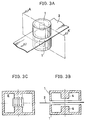
- Fig.lA shows a typical apparatus of the present invention for measuring physical quantities of sheet material.
- a cylindrical re-entrant cavity resonator 1 which is axially symmetrical, is provided with emitting means and receiving means of microwave not shown in the figure. This shows that moisture content of paper in the paper process production is being measured in on-line manner.
- Object 2 to be measured can be any kinds of sheet materials such as grains, various materials of fluid particulate e.g. for forming ceramic, stringy materials, corrugated fiberboard material, various laminate coated like a film base, etc. Even if the object is particulate or fluid, it can be measured as long as it can be converted into a sheet-like shape. Since the object 2 to be measured is inserted into the gap between lower portion of resonator 3 and cavity resonator 1 without contact, measurement can be conducted in non-contact and on-line manner.
- Fig.lB shows a longitudinal section view taken on line A-A' of Fig.lA for explaining the structure of the apparatus in Fig.lA.
- Fig.lB shows that protrusion 4 faces the paper 2 which is the object.
- strong electric fields emitting from the vicinity of the top portion in protrusion 4 distribute vertically against the object.
- the portion to be measured is confined to the area which is almost the same as one of the top portion of the protrusion, so that the moisture content of the minute area of the object can be measured.
- the cavity resonator of an embodiment made of aluminum, whose outer and inner radii are 2.54 cm and 0.9 cm respectively, has a cavity length of 2.99 cm.
- the resonance frequency of 2.9 GH and the Q-value of 7097 are obtained experimentally. It is found that those values are in good agreement with the calculated ones. And it should be noted that the full width at half maximum is only 380 kHz at the resonant freaquency of 2.9 G H , which is extremely narrow. This means that a high Q-value can be obtained by the apparatus of the present invention.
- the Q-value is about 5500 and the half band width is as broad as 700 kHz. It can be said that the resonator of the present invention has a greater sensitivity than the conventional one.
- Another advantage of the apparatus of the invention is that the configuration formed by two electrodes of the cavity resonator does not change even if the concave cylindrical cavity resonator 1 moves horizontally at the time of measuring, because the lower part 3 of the resonator is flat. Therefore stable measurement can be attained.
- the apparatus is easy to manufacture because it is axial symmetry and cylindrical.
- Fig.2A is a modified example of the apparatus shown in Fig.1 for measuring physical quantities.
- Fig.2B is a cross section taken on line A-A' of Fig.2B and Fig.2C shows the measurement principle of the apparatus.
- upper cylindrical cavity resonator 5 and lower cylindrical cavity resonator 6 are faced, and the object 2 to be measured, such as paper, is inserted between them.
- Upper and lower cylinders have respectively a protrusion 4 provided with a penetrating hole, as shown in a cross section of Fig.2B, whose holes in the protrusions are precisely lined up between both resonators.
- Fig.2C shows that the distribution of electric field is dense at the vicinity of the top portion of said protrusion and is vertical against the object.
- Upper and lower cylindrical cavity resonators do not necessarily have the same shape. It is only necessary that its shape gives rise to the electric field distribution at the vicinity of the top portion in the protrusion as shown in Fig.2C.
- Fig.3A is another modified example of the apparatus of Fig.1 for measuring physical quantities.
- Fig.3B is a cross section taken on line A-A' of Fig.3A
- Fig.3C is a drawing to show the principle thereof.
- the apparatus corresponds to the one in which the hole in the apparatus of Fig.2A is filled up. It can be said that the system comprises two same re-entrant cavities shown in Fig.1C.
- Fig.3C shows that electric field in the cavity resonator is extremely strong at the vicinity of the protrusion and is vertical against the object.
- Upper and lower re-entrant resonators do not necessarily have the same shape as in the cases mentioned above.
- any kind of cavity resonator where a protrusion is provided on the area corresponding to the part to be measured, so that electric field distribution becomes dense for the object, can be accepted as the apparatus of the present invention for measuring physical quantities of sheet-like material.
- the cavity resonator of the present invention is not limited to the one made of metal, such as aluminum. It can be the cavity resonator whose body is made of plastics, and whose inside surface is coated with conductive material ,such as Al or Ag, so as to decrease the weight of the resonator.
- each cavity block of about 1m in length, has six re-entrant type cavity resonators.
- Each cavity resonator in the cavity block made of Al, has a cylindrical protrusions.
- Upper plate 8 faced to cavity part 7 is a plate of 1m which is common to six microwave cavity resonators.
- each block of 1m in length is provided with a microwave transmitter can be accepted.
- This system enables to apply commonly microwave to each cavity resonator in a block for microwave measurement so that only one microwave transmitter is enough for one block, which results in reduced costs of the measuring system.
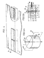
- Fig.5A is a perspective view of cylindrical cavity resonator 1 of the present invention that is suitable for measuring of quantities of stringy materials.
- the cylindrical cavity resonator 1 is made of Al, and provided with an emitting and receiving means 16 of microwave. Reflected microwave is received by the emitting and receiving means of microwave 16.
- the object 2 to be measured is a shape like pipe, rod and fiber. In the embodiment shown in Fig.5, the object 2 to be measured is 0.2mm diameter glass fiber containing minute metal pieces. The physical quantities of the object 2 is obtained from the comparison between the resonance characteristics of the glass fiber with metal pieces and the one of glass fiber without metal pieces.
- protrusion 4 is provided on the center of cylindrical cavity resonator 1, and space 17 is provided on the center of the protrusion 4 for placing the object, which enables measurement in non-contact and on-line manner.
- outside diameter b of the cavity is 60 mm; inside diameter c is 42 mm; the height e of the cavity is 38 mm; inside height d is 25 mm; the diameter g of the protrusion is 42 mm; the distance a between the upper edge of the cavity and the top of the protrusion is 16.1 mm; the inside diameter of space 17 is 3.2 mm.
- D/A converter 19 converts directing signal from CPU 18 into analog signals which are put into VCO 20 and x axis of x-y recorder 15. Microwave generated at VCO 20 is applied to y axis of x-y recorder 15 through detector 13 and amplifier 14 for recording the resonance characteristic of each object 2 to be measured.
- cylindrical cavity resonator 1 of the present invention for stringy materials is not restricted to the one shown in Fig.5B. Available are the one that a hole is not provided on the bottom plate as shown in Fig.10, or the one that protrusions are provided on both ends as shown in Fig.ll.
- the cavity resonator 1 of the present invention is not necessarily made of metal, such as Aluminum. It can be one wholly made of plastics the inside surface of which is coated with conductive material, such as Al and Ag, in order to decrease its weight.
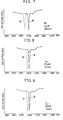
- Fig.9 shows the result of the measured resonance frequency when grass fibers of 0.2mm ⁇ , containing Ni pieces of 4mmo in diameter and 20mm in length, are inserted into the space 17 of circular cavity resonator 1 as shown in Fig.5.
- Curve a shows the reflection characteristics of glass fiber of 0.2mmo without Ni pieces, and curve b does that containing Ni pieces.
- Fig.7 it can be found that the resonation frequency of curb b is displaced by 25MH z with reference to curb a, because of the existence of minute Ni pieces. This concludes that the measurement apparatus for physical quantities of this invention can detect minute Ni pieces with extremely great sensitivity.
- Fig.8 shows the result of measured resonance frequency of glass fiber of 0.2mm ⁇ , containing Au pieces of 25mmo in diameter and 5mm in length, and one of the same glass fiber without Au pieces. This example also shows that the measuring apparatus of the invention can definitely detect the existence of Au pieces.
- Fig.9 shows the result of measured resonance frequency of glass fiber of 0.2mm ⁇ , containing Cu pieces of 10mm ⁇ in diameter and 5mm in length, and one of the same glass fiber without Cu pieces.
- the object was paper.
- the moisture content and basis weight were mersured by a conventional method for 1500 samples which had been kept in a thermostatic chamber. They were obtained from 30 pieces of paper whose moisture content was in the range of 3%-13% and 50 pieces of paper whose basis weight was in the range of 10g/m 2 -800g/m 2 .
- the frequency f and voltage v of maximum resonance of microwave were measured on said 1,500 samples and 3,000 measured data were obtained.
Abstract
Dispositif de mesure de quantités physiques, consistant en un résonateur à cavité à micro-ondes (1) dont la structure comporte un élément en saillie (4) sur son axe central. Le matériau à mesurer (2) est placé sur une partie centrale (17) de l'élément en saillie (4) en parallèle avec ce dernier ou perpendiculairement audit élément (4), de sorte que le champ électrique est concentré dans la zone où la mesure doit être effectuée. Cela permet de mesurer correctement les quantités physiques dans une minuscule partie de la zone où la mesure doit être effectuée. Selon ce procédé de mesure de quantités physiques, la fréquence et la tension sont mesurées en un point de résonance maximum des micro-ondes dans le matériau à mesurer, et une teneur en humidité x et un poids de base y sont calculés à l'aide d'une équation caractéristique qui comprend au moins le terme du produit de la teneur en humidité y et du poids de base y. Cela permet de calculer aisément et correctement la teneur en humidité et le poids de base.
Applications Claiming Priority (2)
| Application Number | Priority Date | Filing Date | Title |
|---|---|---|---|
| JP61293026A JPS63145951A (ja) | 1986-12-09 | 1986-12-09 | 糸状材料の物性量測定装置 |
| JP293026/86 | 1986-12-09 |
Publications (2)
| Publication Number | Publication Date |
|---|---|
| EP0292571A1 true EP0292571A1 (fr) | 1988-11-30 |
| EP0292571A4 EP0292571A4 (fr) | 1989-10-04 |
Family
ID=17789524
Family Applications (1)
| Application Number | Title | Priority Date | Filing Date |
|---|---|---|---|
| EP19870907989 Withdrawn EP0292571A4 (fr) | 1986-12-09 | 1987-12-08 | Dispositif et procede de mesure de quantites physiques. |
Country Status (4)
| Country | Link |
|---|---|
| US (1) | US4890054A (fr) |
| EP (1) | EP0292571A4 (fr) |
| JP (1) | JPS63145951A (fr) |
| WO (1) | WO1988004423A1 (fr) |
Cited By (16)
| Publication number | Priority date | Publication date | Assignee | Title |
|---|---|---|---|---|
| EP0468057A1 (fr) * | 1990-02-05 | 1992-01-29 | Dipole Electronics Co. Ltd. | Detecteur d'une substance conductrice melangee dans un materiau filandreux |
| EP0509187A1 (fr) * | 1991-04-18 | 1992-10-21 | Barco Automation, Naamloze Vennootschap | Procédé de mesure de la masse d'un produit non rigide défilant dans un appareil de mesure |
| ES2047438A2 (es) * | 1992-03-04 | 1994-02-16 | Univ Zaragoza | Dispositivo de control automatico de seleccion y cambio de escalas de un medidor de ondas estacionarias. |
| GB2277803A (en) * | 1993-05-05 | 1994-11-09 | Jerry Geoffrey Assenheim | Microwave moisture determination |
| EP0753755A2 (fr) * | 1995-07-14 | 1997-01-15 | Hauni Maschinenbau Aktiengesellschaft | Dispositif de mesure de la constante diélectrique complexe du tabac |
| EP0758085A2 (fr) * | 1995-08-08 | 1997-02-12 | Appleton Mills | Procédés et appareil de détection de l'humidité |
| EP0889321A1 (fr) * | 1997-07-02 | 1999-01-07 | TEWS ELEKTRONIK Dipl.-Ing. Manfred Tews | Capteur d'humidité et de densité |
| EP0967479A2 (fr) * | 1998-06-25 | 1999-12-29 | Allen-Bradley Company, LLC | Méthode et dispositif de mesure de la densité d'une substance avec compensation de l'eau libre |
| EP1004874A1 (fr) * | 1998-11-26 | 2000-05-31 | Hauni Maschinenbau AG | Boítier-résonateur à micro-ondes |
| WO2008015553A2 (fr) * | 2006-08-03 | 2008-02-07 | G.D Societa' Per Azioni | Dispositif pour détecter une caractéristique d'une matière fibreuse |
| DE202006020481U1 (de) | 2006-05-09 | 2008-08-21 | Ams Advanced Microwave Systems Gmbh | Mikrowellenmessvorrichtung zur Bestimmung mindestens einer Messgröße an einem Produkt |
| US7759947B2 (en) | 2006-12-15 | 2010-07-20 | Voith Patent Gmbh | Method and apparatus for determining the moisture of a running material web |
| DE102011083051A1 (de) * | 2011-09-20 | 2013-03-21 | Hauni Maschinenbau Ag | Mikrowellenresonatorgehäuse |
| CN107655902A (zh) * | 2017-08-25 | 2018-02-02 | 天津大学 | 一种圆形微波谐振腔传感器溶液浓度测量方法 |
| EP2848133B1 (fr) | 2013-07-16 | 2018-05-30 | Hauni Maschinenbau GmbH | Système et procédé de contrôle d'articles en forme de tige de l'industrie de traitement du tabac |
| EP3158325B1 (fr) | 2014-06-17 | 2020-04-01 | Hauni Maschinenbau GmbH | Dispositif de mesure à micro-ondes, ensemble et procédé de contrôle d'articles en forme de bâtonnet ou d'un boudin de matière issus de l'industrie de transformation du tabac, et machine de l'industrie de transformation du tabac |
Families Citing this family (34)
| Publication number | Priority date | Publication date | Assignee | Title |
|---|---|---|---|---|
| JPS63210757A (ja) * | 1987-02-27 | 1988-09-01 | Nippon Glass Fiber Co Ltd | 非電導性繊維中の導電性物質を検出する為の装置及び方法 |
| JPH01172738A (ja) * | 1987-12-28 | 1989-07-07 | Asahi Fiber Glass Co Ltd | 誘電体の検出方法 |
| AU614904B2 (en) * | 1989-07-31 | 1991-09-12 | American Telephone And Telegraph Company | Measuring and controlling the thickness of a coating on a elongated article |
| FR2661500B1 (fr) * | 1990-04-25 | 1994-01-07 | Aerospatiale Ste Nationale Indle | Cavite hyperfrequence adaptee a la mesure des caracteristiques electromagnetiques d'un materiau filiforme en defilement. |
| GB9121678D0 (en) * | 1991-10-12 | 1991-11-27 | Unaform Ltd | Microwave drainage meter |
| DE4211362C2 (de) * | 1992-04-04 | 1995-04-20 | Berthold Lab Prof Dr | Vorrichtung zur Bestimmung von Materialparametern durch Mikrowellenmessungen |
| GB2294326A (en) * | 1994-10-06 | 1996-04-24 | Scapa Group Plc | Moisture detection meter |
| US5666061A (en) * | 1994-11-09 | 1997-09-09 | James Instruments Inc. | Apparatus and method for measurement of moisture concentration in granular materials |
| US5594351A (en) * | 1995-05-23 | 1997-01-14 | The United States Of America As Represented By The Administrator Of The National Aeronautics And Space Administration | Apparatus for use in determining surface conductivity at microwave frequencies |
| US5838158A (en) * | 1995-08-08 | 1998-11-17 | Appleton Mills | Measuring system for measuring the amount of dielectric in a web |
| CN1198790A (zh) * | 1995-10-05 | 1998-11-11 | 美国3M公司 | 柔性突起的路面标志器及其安装装置和方法 |
| US5714697A (en) * | 1996-06-19 | 1998-02-03 | Xerox Corporation | Sheet materials mass measuring system |
| WO1999006788A2 (fr) * | 1997-07-31 | 1999-02-11 | Mikrowellen-Technologie Und Sensoren Gmbh | Dispositif et procede permettant de mesurer une distance |
| DE19734713A1 (de) | 1997-08-11 | 1999-02-18 | Mikrowellen Technologie Und Se | Radar-Entfernungsmeßeinrichtung |
| DE29716639U1 (de) * | 1997-09-16 | 1999-01-21 | Tews Elektronik | Mikrowellen-Streufeldsensor zur Feuchte- und/oder Dichtemessung |
| EP1114299B1 (fr) | 1998-08-31 | 2005-02-02 | Malcam Ltd. | Resonateur hyperfrequence pour l'evaluation continue de matieres fibreuses |
| AU2001275607A1 (en) * | 2000-06-27 | 2002-01-08 | Universite Catholique De Louvain | Measurement of cylindrical objects through laser telemetry |
| US6467977B2 (en) * | 2000-12-19 | 2002-10-22 | Hewlett-Packard Company | Media weight sensor using a resonant piezoelectric element |
| US6485205B2 (en) * | 2000-12-19 | 2002-11-26 | Hewlett-Packard Company | Media weight sensor using an acoustic resonator |
| DE10112499B4 (de) * | 2001-03-15 | 2010-08-19 | Hauni Maschinenbau Ag | Resonatoreinrichtung, insbesondere Mikrowellenresonatoreinrichtung |
| WO2005012887A1 (fr) * | 2003-07-31 | 2005-02-10 | Oji Paper Co., Ltd. | Procede et dispositif pour mesurer une teneur en humidite |
| DE202005001756U1 (de) * | 2004-02-12 | 2005-05-04 | Trützschler GmbH & Co KG | Mikrowellensensor zur Messung einer dielektrischen Eigenschaft eines Produkts |
| US20060208194A1 (en) * | 2005-03-18 | 2006-09-21 | Voith Paper Patent Gmbh | Microwave mass measuring device and process |
| JP2009535647A (ja) * | 2006-05-01 | 2009-10-01 | マサチューセッツ インスティテュート オブ テクノロジー | フィルタ負荷判定のためのマイクロ波検出 |
| FI121195B (fi) * | 2006-06-22 | 2010-08-13 | Senfit Oy | Menetelmä ja mittalaite radioaaltomittausta varten |
| US7570136B2 (en) * | 2006-09-20 | 2009-08-04 | Alcatel-Lucent Usa Inc. | Re-entrant resonant cavities, filters including such cavities and method of manufacture |
| US8324989B2 (en) * | 2006-09-20 | 2012-12-04 | Alcatel Lucent | Re-entrant resonant cavities and method of manufacturing such cavities |
| DE102006051577B4 (de) * | 2006-11-03 | 2011-07-21 | Deutsche Solar AG, 09599 | Vorrichtung und Verfahren zur Erfassung elektrischer Eigenschaften einer Probe aus einem anregbaren Material |
| DE102007025815A1 (de) * | 2007-06-02 | 2008-12-04 | Voith Patent Gmbh | Verfahren und Vorrichtung zur Messung wenigstens einer Qualitätsgröße einer Faserstoffbahn |
| DE102010063232A1 (de) * | 2010-12-16 | 2012-06-21 | Voith Patent Gmbh | Vorrichtung und Verfahren zur Flächengewichtsbestimmung |
| JP6017126B2 (ja) * | 2011-09-27 | 2016-10-26 | 旭化成エンジニアリング株式会社 | 異物検出方法及び異物検出装置 |
| JP6222360B2 (ja) * | 2014-06-25 | 2017-11-01 | 宇部興産株式会社 | 誘電体非接触伝送装置及び非接触伝送方法 |
| RU2579359C1 (ru) * | 2015-02-05 | 2016-04-10 | Федеральное государственное бюджетное учреждение науки Институт проблем управления им. В.А. Трапезникова РАН | Способ измерения физической величины |
| DE102015206650A1 (de) * | 2015-04-14 | 2016-10-20 | Bhs Corrugated Maschinen- Und Anlagenbau Gmbh | Anlage zur Herstellung einer Wellpappe-Bahn |
Citations (1)
| Publication number | Priority date | Publication date | Assignee | Title |
|---|---|---|---|---|
| US4095475A (en) * | 1976-04-22 | 1978-06-20 | Massachusetts Institute Of Technology | Apparatus and method whereby wave energy is correlated with geometry of a manufactured part or the like or to positional relationships in a system |
Family Cites Families (13)
| Publication number | Priority date | Publication date | Assignee | Title |
|---|---|---|---|---|
| US3079551A (en) * | 1958-01-23 | 1963-02-26 | Beloit Iron Works | Apparatus and method for measurement of moisture content |
| SU398896A1 (ru) * | 1972-04-18 | 1973-09-27 | Н. И. Матушкин , Д. П. Буртовой Харьковский институт радиоэлектроники | УСТРОЙСТВО дл ИЗМЕРЕНИЯ ЭЛЕКТРИЧЕСКИХ |
| DE2907964C2 (de) * | 1979-03-01 | 1981-02-26 | Hermann Berstorff Maschinenbau Gmbh, 3000 Hannover | Verfahren zum Prüfen der dielektrischen Erwärmbarkeit und Vorrichtung zur Durchführung des Verfahrens |
| JPS5830534A (ja) * | 1981-08-18 | 1983-02-23 | Mitsubishi Electric Corp | 磁性粒子式電磁連結装置 |
| JPS59197843A (ja) * | 1983-04-26 | 1984-11-09 | Yokogawa Hokushin Electric Corp | マイクロ波水分計 |
| JPS59224547A (ja) * | 1983-06-03 | 1984-12-17 | Kanzaki Paper Mfg Co Ltd | 繊維シ−トの繊維配向測定方法 |
| JPS6020138A (ja) * | 1983-07-14 | 1985-02-01 | Nippon Electric Glass Co Ltd | ガラス繊維の欠陥を検出する方法 |
| US4600879A (en) * | 1984-06-15 | 1986-07-15 | Scully John P | Water moisture measuring instrument and method |
| JPS6183946A (ja) * | 1984-10-01 | 1986-04-28 | Kanzaki Paper Mfg Co Ltd | シ−ト状物質の配向測定方法 |
| JPH0540568Y2 (fr) * | 1985-08-26 | 1993-10-14 | ||
| JPH0658331B2 (ja) * | 1985-11-26 | 1994-08-03 | 株式会社ダイポ−ル | 平面状材料の物性量測定装置 |
| JPH0663986B2 (ja) * | 1986-01-21 | 1994-08-22 | 株式会社ダイポール | 平面状材料の物性量測定装置 |
| JPH06162845A (ja) * | 1992-11-19 | 1994-06-10 | Furukawa Electric Co Ltd:The | 光ファイバ内蔵碍子 |
-
1986
- 1986-12-09 JP JP61293026A patent/JPS63145951A/ja active Granted
-
1987
- 1987-12-08 WO PCT/JP1987/000950 patent/WO1988004423A1/fr not_active Application Discontinuation
- 1987-12-08 US US07/243,336 patent/US4890054A/en not_active Expired - Fee Related
- 1987-12-08 EP EP19870907989 patent/EP0292571A4/fr not_active Withdrawn
Patent Citations (1)
| Publication number | Priority date | Publication date | Assignee | Title |
|---|---|---|---|---|
| US4095475A (en) * | 1976-04-22 | 1978-06-20 | Massachusetts Institute Of Technology | Apparatus and method whereby wave energy is correlated with geometry of a manufactured part or the like or to positional relationships in a system |
Non-Patent Citations (1)
| Title |
|---|
| See also references of WO8804423A1 * |
Cited By (23)
| Publication number | Priority date | Publication date | Assignee | Title |
|---|---|---|---|---|
| EP0468057A4 (en) * | 1990-02-05 | 1992-11-19 | Dipole Electronics Co. Ltd. | Detector for conductive substance mixed in string-like material |
| EP0468057A1 (fr) * | 1990-02-05 | 1992-01-29 | Dipole Electronics Co. Ltd. | Detecteur d'une substance conductrice melangee dans un materiau filandreux |
| EP0509187A1 (fr) * | 1991-04-18 | 1992-10-21 | Barco Automation, Naamloze Vennootschap | Procédé de mesure de la masse d'un produit non rigide défilant dans un appareil de mesure |
| ES2047438A2 (es) * | 1992-03-04 | 1994-02-16 | Univ Zaragoza | Dispositivo de control automatico de seleccion y cambio de escalas de un medidor de ondas estacionarias. |
| GB2277803A (en) * | 1993-05-05 | 1994-11-09 | Jerry Geoffrey Assenheim | Microwave moisture determination |
| EP0753755A2 (fr) * | 1995-07-14 | 1997-01-15 | Hauni Maschinenbau Aktiengesellschaft | Dispositif de mesure de la constante diélectrique complexe du tabac |
| EP0753755A3 (fr) * | 1995-07-14 | 2000-07-12 | Hauni Maschinenbau Aktiengesellschaft | Dispositif de mesure de la constante diélectrique complexe du tabac |
| EP0758085A2 (fr) * | 1995-08-08 | 1997-02-12 | Appleton Mills | Procédés et appareil de détection de l'humidité |
| EP0758085A3 (fr) * | 1995-08-08 | 1999-09-01 | Appleton Mills | Procédés et appareil de détection de l'humidité |
| EP0889321A1 (fr) * | 1997-07-02 | 1999-01-07 | TEWS ELEKTRONIK Dipl.-Ing. Manfred Tews | Capteur d'humidité et de densité |
| EP0967479A3 (fr) * | 1998-06-25 | 2002-11-27 | Allen-Bradley Company, LLC | Méthode et dispositif de mesure de la densité d'une substance avec compensation de l'eau libre |
| EP0967479A2 (fr) * | 1998-06-25 | 1999-12-29 | Allen-Bradley Company, LLC | Méthode et dispositif de mesure de la densité d'une substance avec compensation de l'eau libre |
| EP1004874A1 (fr) * | 1998-11-26 | 2000-05-31 | Hauni Maschinenbau AG | Boítier-résonateur à micro-ondes |
| US6417676B1 (en) | 1998-11-26 | 2002-07-09 | Hauni Maschinenbau Ag | Method and apparatus for applying microwaves to measure the moisture content of material |
| US7199592B2 (en) | 1998-11-26 | 2007-04-03 | Hauni Maschinenbau Ag | Method and apparatus for applying microwaves to measure the moisture content of material |
| DE202006020481U1 (de) | 2006-05-09 | 2008-08-21 | Ams Advanced Microwave Systems Gmbh | Mikrowellenmessvorrichtung zur Bestimmung mindestens einer Messgröße an einem Produkt |
| WO2008015553A2 (fr) * | 2006-08-03 | 2008-02-07 | G.D Societa' Per Azioni | Dispositif pour détecter une caractéristique d'une matière fibreuse |
| WO2008015553A3 (fr) * | 2006-08-03 | 2008-07-10 | Gd Spa | Dispositif pour détecter une caractéristique d'une matière fibreuse |
| US7759947B2 (en) | 2006-12-15 | 2010-07-20 | Voith Patent Gmbh | Method and apparatus for determining the moisture of a running material web |
| DE102011083051A1 (de) * | 2011-09-20 | 2013-03-21 | Hauni Maschinenbau Ag | Mikrowellenresonatorgehäuse |
| EP2848133B1 (fr) | 2013-07-16 | 2018-05-30 | Hauni Maschinenbau GmbH | Système et procédé de contrôle d'articles en forme de tige de l'industrie de traitement du tabac |
| EP3158325B1 (fr) | 2014-06-17 | 2020-04-01 | Hauni Maschinenbau GmbH | Dispositif de mesure à micro-ondes, ensemble et procédé de contrôle d'articles en forme de bâtonnet ou d'un boudin de matière issus de l'industrie de transformation du tabac, et machine de l'industrie de transformation du tabac |
| CN107655902A (zh) * | 2017-08-25 | 2018-02-02 | 天津大学 | 一种圆形微波谐振腔传感器溶液浓度测量方法 |
Also Published As
| Publication number | Publication date |
|---|---|
| WO1988004423A1 (fr) | 1988-06-16 |
| EP0292571A4 (fr) | 1989-10-04 |
| JPS63145951A (ja) | 1988-06-18 |
| US4890054A (en) | 1989-12-26 |
| JPH0575264B2 (fr) | 1993-10-20 |
Similar Documents
| Publication | Publication Date | Title |
|---|---|---|
| EP0292571A1 (fr) | Dispositif et procede de mesure de quantites physiques | |
| US6496018B1 (en) | Method and device for measuring dielectric constant | |
| US4257001A (en) | Resonant circuit sensor of multiple properties of objects | |
| US4800350A (en) | Dielectric waveguide using powdered material | |
| US5397993A (en) | Method for measuring the material moisture content of a material under test using microwaves | |
| JP3515375B2 (ja) | 湿度及び密度センサー用マイクロ波共振器 | |
| US4623835A (en) | Web thickness sensor using loop-gap resonator | |
| CA1277707C (fr) | Capteurs d'epaisseur et d'humidite combines du type a balayage pour tissuen defilement | |
| CA2007649A1 (fr) | Detecteur de niveau liquide capacitif | |
| EP1703275A1 (fr) | Appareil et procédé pour déterminer le grammage de papier ou la densité de pulpe pendant la fabrication de papier en utlisant des micro ondes | |
| US4739249A (en) | Method and apparatus for the measurement of the properties of sheet- or foil-like materials of low electrical conductivity | |
| US4924173A (en) | Shielded capacitance standard | |
| WO2000028615A1 (fr) | Detecteur hyperfrequences a guide d'ondes dielectrique | |
| GB2038483A (en) | Measuring thickness capacitively | |
| EP0287725B1 (fr) | Procédé pour mesurer des propriétés de feuilles ayant une faible conductivité électrique | |
| JPS5639447A (en) | Device for measuring water content in sheet material | |
| FI69372B (fi) | Maetmetod och apparat foer maetning av fasta kornaktiga aemnens massfloede och fuktighet eller naogon annan egenskap | |
| EP0171133B1 (fr) | Appareil électrique pour la mesure de l'humidité | |
| JP2705257B2 (ja) | 液位検出装置 | |
| JPS62124449A (ja) | 平面材料の物性測定装置 | |
| RU2221228C2 (ru) | Датчик давления | |
| JPS5830534B2 (ja) | シ−ト状物体の含水率、坪量測定装置 | |
| JPS63200155U (fr) | ||
| RU2060490C1 (ru) | Устройство для измерения влажности диэлектриков | |
| Kraszewski et al. | Resonant-cavity perturbation measurement for mass determination of the perturbing object |
Legal Events
| Date | Code | Title | Description |
|---|---|---|---|
| PUAI | Public reference made under article 153(3) epc to a published international application that has entered the european phase |
Free format text: ORIGINAL CODE: 0009012 |
|
| 17P | Request for examination filed |
Effective date: 19880819 |
|
| AK | Designated contracting states |
Kind code of ref document: A1 Designated state(s): AT BE CH DE FR GB IT LI LU NL SE |
|
| RBV | Designated contracting states (corrected) |
Designated state(s): DE FR GB SE |
|
| A4 | Supplementary search report drawn up and despatched |
Effective date: 19891004 |
|
| 17Q | First examination report despatched |
Effective date: 19910429 |
|
| STAA | Information on the status of an ep patent application or granted ep patent |
Free format text: STATUS: THE APPLICATION IS DEEMED TO BE WITHDRAWN |
|
| 18D | Application deemed to be withdrawn |
Effective date: 19921006 |