EP0290939B1 - Vorrichtung zur Erzeugung von Druckpulsen in Bohrspülungsmedien - Google Patents
Vorrichtung zur Erzeugung von Druckpulsen in Bohrspülungsmedien Download PDFInfo
- Publication number
- EP0290939B1 EP0290939B1 EP88107135A EP88107135A EP0290939B1 EP 0290939 B1 EP0290939 B1 EP 0290939B1 EP 88107135 A EP88107135 A EP 88107135A EP 88107135 A EP88107135 A EP 88107135A EP 0290939 B1 EP0290939 B1 EP 0290939B1
- Authority
- EP
- European Patent Office
- Prior art keywords
- valve body
- main valve
- outer part
- diameter
- drilling fluid
- Prior art date
- Legal status (The legal status is an assumption and is not a legal conclusion. Google has not performed a legal analysis and makes no representation as to the accuracy of the status listed.)
- Expired - Lifetime
Links
- 238000005553 drilling Methods 0.000 title claims description 24
- 239000012530 fluid Substances 0.000 title claims description 24
- 230000007704 transition Effects 0.000 claims description 18
- 238000011144 upstream manufacturing Methods 0.000 claims description 4
- 239000011248 coating agent Substances 0.000 claims description 2
- 238000000576 coating method Methods 0.000 claims description 2
- 230000005484 gravity Effects 0.000 claims description 2
- UONOETXJSWQNOL-UHFFFAOYSA-N tungsten carbide Chemical compound [W+]#[C-] UONOETXJSWQNOL-UHFFFAOYSA-N 0.000 claims description 2
- 238000007747 plating Methods 0.000 claims 2
- 230000003014 reinforcing effect Effects 0.000 claims 2
- 238000006073 displacement reaction Methods 0.000 claims 1
- 230000001133 acceleration Effects 0.000 description 2
- 230000015572 biosynthetic process Effects 0.000 description 2
- 238000013461 design Methods 0.000 description 2
- 238000012423 maintenance Methods 0.000 description 2
- 125000006850 spacer group Chemical group 0.000 description 2
- 238000013459 approach Methods 0.000 description 1
- 230000005540 biological transmission Effects 0.000 description 1
- 238000010276 construction Methods 0.000 description 1
- 230000007423 decrease Effects 0.000 description 1
- 230000003247 decreasing effect Effects 0.000 description 1
- 230000000694 effects Effects 0.000 description 1
- 238000011156 evaluation Methods 0.000 description 1
- 238000000034 method Methods 0.000 description 1
- 238000007493 shaping process Methods 0.000 description 1
- 230000035939 shock Effects 0.000 description 1
- 230000003068 static effect Effects 0.000 description 1
Images

Classifications
-
- E—FIXED CONSTRUCTIONS
- E21—EARTH OR ROCK DRILLING; MINING
- E21B—EARTH OR ROCK DRILLING; OBTAINING OIL, GAS, WATER, SOLUBLE OR MELTABLE MATERIALS OR A SLURRY OF MINERALS FROM WELLS
- E21B47/00—Survey of boreholes or wells
- E21B47/12—Means for transmitting measuring-signals or control signals from the well to the surface, or from the surface to the well, e.g. for logging while drilling
- E21B47/14—Means for transmitting measuring-signals or control signals from the well to the surface, or from the surface to the well, e.g. for logging while drilling using acoustic waves
- E21B47/18—Means for transmitting measuring-signals or control signals from the well to the surface, or from the surface to the well, e.g. for logging while drilling using acoustic waves through the well fluid, e.g. mud pressure pulse telemetry
Definitions
- the invention relates to a device for generating pressure pulses in a drilling fluid flowing down a drill pipe string in an embodiment according to the preamble of claim 1.
- the outer part of the valve forms a valve seat which limits the upward movement of the main valve body into the operating end position as a stop and blocks the central main passage for drilling fluid in engagement with the main valve body.
- the carrier body determines the starting position for the main valve body as a stop. The sum of the downward hydraulic forces exerted by the drilling fluid on the main valve body in its starting position when the auxiliary valve is open exceeds that of the upward hydraulic forces, so that the main valve body is fixed in its starting position when the auxiliary valve is open. By closing the auxiliary valve, this pressure ratio is reversed, with the result that the main valve body moves upward into its operating end position limited by the valve seat.
- the invention has for its object to provide a device of the type mentioned, the valve works smoothly with a simple structural design, avoids mechanical wear and is perfectly functional even after a long period of operation and without maintenance.
- the main valve body reaches a stop-free operating end position, which is determined only by the balance of the forces acting on it, so that impacts associated with the pressure pulse generation, which result from the impact of the main valve body on a stop specifying the operating end position, are avoided.
- the avoidance of shock phenomena is also accompanied by the avoidance of wear and damage, which is greater the higher the speed of the upward movement at the time the main valve body hits its stop.
- an acceleration or speed course over the stroke path can be selected for the upward movement of the main valve body which determines the shape of the pressure pulse, which is completely free of Considerations that have to be taken when the operating end position is given by the stop due to the sudden braking of the main valve body.
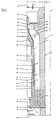
- the device for generating pressure pulses in a drilling fluid flowing down a drill pipe string 1 downwards in the direction of arrow 2 - that after exiting through a rotary drill bit D at the end of the drill pipe string 1 into the borehole B in the annular space S between its wall and the outer wall of the drill pipe string 1 upwards flows - consists essentially of a valve V arranged in the drill pipe string 1, which comprises an outer part 3, a main valve body 4 and a carrier body 5.
- the device for generating pressure pulses is part of a device E for the determination and remote transmission of information or works together with such a device, which is likewise arranged in the drill pipe string 1 generally immediately below the valve V.
- the pressure pulses generated in the drilling fluid which is pumped downwards by means of a pump P, are received by a pressure sensor R and are fed by this to an evaluation device T which evaluates the signals received.
- the stationarily supported in the drill pipe string 1, essentially tubular outer part 3 comprises an upper ring part 6 with a central axial passage opening 7, the cross section of which is considerably smaller than the clear cross section in the drill pipe string 1 above the valve V. Furthermore, the outer part 3 supports a foot part 8 of the Carrier part 5 stationary in its lower area, which is closed in its central area 9 except for an axial through opening 10. Between the area 9 and the inside of the outer part 3, however, remain through the circumferential openings 11 'for the drilling fluid, which flows down an annular outer flow channel 11 between the outer part 3 and the main valve body 4.
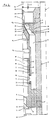
- the foot part 8 forms a separate or also integral part of the carrier body 5, which is essentially tubular and has a central through opening 12 in its upper region, to which the through opening 10 in the foot part 8 connects. This has at its lower end a valve seat 13, which is also the outlet opening of a Forms inner flow channel which is delimited in its lower region by the axial through openings 12, 10.
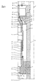
- An auxiliary valve body 14 is assigned to the valve seat or the outlet opening 13 and is actuated by means of a drive, which is only indicated schematically at 15, e.g. of an electromagnet, can be moved from its open position shown in FIG. 2 into a closed position illustrated in FIG. 3, in which it closes the outlet opening 13.
- a drive which is only indicated schematically at 15, e.g. of an electromagnet, can be moved from its open position shown in FIG. 2 into a closed position illustrated in FIG. 3, in which it closes the outlet opening 13.
- the carrier body 5 is essentially cylindrical in the area of the outer surface 16 of its upper main part 17 and, on the inside, delimits with this outer surface 16 an annular gap 18 which is delimited on the outside by an essentially cylindrical inner surface 19 of a tubular extension 20 of the main valve body 4.
- the starting positions of the main valve body 4 shown in FIG. 2 over their entire length opposite surfaces 16, 19 define an overlap area between the main valve body 4 and the carrier body 5, the length of which decreases as soon as the main valve body 4 executes an upward movement.
- Drilling fluid can flow freely through the cylindrical gap 18 between the main valve body 4 and the carrier body 5 and is flowed through by drilling fluid in all positions of the main valve body 4 relative to the carrier body 5 due to a pressure drop between the drilling fluid in the passage opening 12 and in the external flow channel 11.
- the gap 18 forms either a full length or, as shown, in sub-regions 18 'arranged one behind the other Throttle section in which the gap width is less than a hundredth of the diameter of the annular gap 18 and is preferably in the range between 0.05 mm and 0.5 mm, preferably 0.15 mm.
- the main valve body 4 has an upper end part 22, which is closed except for a through opening 21, which has a conical transition area 23 on the outside in the example shown and merges into a tubular extension 24 in its central area.
- This extension 24 provides side openings 25 which are connected to the through opening 21, is closed at its front end 26 and, in the starting position of the main valve body (FIG. 2), has a position in which the lower edge 27 of the side openings 25 is in the cylindrical through opening 7 is located in the ring part 6 of the outer part 3.
- These side openings 25 form the inlet opening for the inner flow channel surrounded in its upper region by the through opening 21 and then continued by the through openings 10, 12.
- the extension 24 thus forms a type of pitot tube and has an essentially constant outer diameter over its length.
- the diameter increases steadily with increasing distance from the upper end 26 of the main valve body 4, to a diameter d1, which in the example shown is approximately the same size as the diameter d2, which forms a cylindrical constriction area Through opening 7. Furthermore, the diameter d1 is substantially equal to the diameter d3 of the surface 19 of the part 20 of the main valve body 4. The dimensioning of the diameters or their coordination will be discussed further below.
- the annular body 6 of the outer part 3 also has a transition region 28, the diameter of which increases steadily with increasing axial distance from the upper end of the outer part 3, specifically in the exemplary embodiment shown to form a conical widening.
- the outer part 3 and the main valve body 4 delimit between them a throttle section 29 in the upper region of the external flow channel 11, the flow cross section of which can be varied depending on the position of the main valve body 4.
- This throttle section 29 begins, taking into account the starting and operating end positions of the main valve body 4, a bit upstream of the transition area 28 of the outer part 3 and ends a bit below the transition area 23 of the main valve body 4, the throttle section 29 between the transition areas 23, 28 presents a nozzle area with an overall increasing flow cross section downstream. This is achieved in that the diameter of the transition area 28 of the outer part 3 increases more than that of the transition area 23, which can also be achieved with curved surfaces in the transition areas 23, 28.
- the surface of the main valve body 4 is in the area the throttle section 29 is provided with an armor 30, which is preferably formed by a hard coating of tungsten carbide.
- the main valve body 4 In its starting position (FIG. 2), the main valve body 4 can be supported with the lower front end 31 on a shoulder 32 of the carrier body 5, but in order to change the starting position at least one annular spacer 33 can be provided, which is located between the lower front end 31 of the main valve body 4 and the shoulder 32 of the carrier body 5 takes place. With the help of such spacers, the starting position of the main valve body 4 can be shifted upwards in order to take account of changed flow conditions for the drilling fluid, which are caused by a lower volume flow per unit time.
- the main valve body 4 is assigned a schematically illustrated sleep 24, which prescribes an upper end of movement position (FIG. 4) above the operating end position (FIG. 3), in which a residual passage for drilling fluid still remains between the main valve body 4 and the outer part 3.
- the main valve body 4 only reaches this movement end position when the drill pipe string 1 is lowered into the borehole B, e.g. in the course of a round trip, when the drilling fluid present in the borehole B flows upwards through the internal flow channel 21, 12, 10 of the valve V and tries to take the main valve body 4 upwards.
- This stop 34 can, however, also be omitted if a bypass opening indicated by dashed lines at 35 is provided in the ring part 6.
- the device E To generate a pressure pulse in the drilling fluid, the device E the auxiliary valve 13, 14 is closed and thus the flow through the internal flow channel 21, 12, 10 is prevented.
- this inner flow channel 21, 12, 10 a pressure builds up in the drilling fluid that essentially corresponds to the pressure of the drilling fluid at the level of the lower edges 27 of the side openings 25.
- the pressure drop occurring due to the flow through the gap 18 is kept within narrow, clearly definable limits because of the formation of the gap 18 as a narrow throttle section.
- This pressure which builds up in the inner flow channel 21, 12, 10 when the auxiliary valve 13, 14 is closed, exerts upward hydraulic forces on the main valve body 4, the sum of which, taking into account the inner diameter d3 of the main valve body 4, which determines the hydraulically effective inner surface, the sum of the downward hydraulic forces on the Main valve body 4 plus the gravitational forces acting thereon.
- This sum of the axially downward hydraulic forces on the main valve body 4 is determined in the starting position of the main valve body 4 according to FIG. 2, taking into account the outer diameter d1 which determines the hydraulically effective outer surface, and is composed of statically and dynamically active forces, since the main valve body 4 is of drilling fluid is constantly flowed around.
- the diameters d1 and d3 are matched to one another and to the diameter d2 such that the upward force resultant is relatively small at the point in time at which the main valve body 4 begins to move upward from its initial position after the auxiliary valve 13, 14 has closed is initially increasing with increasing stroke length and then decreasing again until it finally reaches the value zero.
- the main valve body 4 In the position in which the sum of all the forces acting on the main valve body 4 has the value zero, the main valve body 4 assumes its end position which determines the pressure pulse, as illustrated in FIG. 3, which shows that in this position the lower edge 27 of the side openings 25 is upstream of the constriction area 7 of the outer part. If the auxiliary valve 13, 14 is then opened again, the force ratio reverses again and the main valve body 4 moves back into its starting position according to FIG. 2.
- the diameters d1, d2 and d3, By coordinating on the one hand the diameters d1, d2 and d3, through which the basic static hydraulic conditions are determined, by choosing the position of the lower edge 27 of the side openings 25 to the constriction area 7 of the outer part 3, by means of which the internal pressure in the main valve body 4 and its change during the upward movement can be determined, and by shaping the transition areas 23, 28, which can be influenced by the dynamic forces via the flow behavior in the throttle section 29, the force ratios on the main valve body 4 during the upward and downward movement can be designed so that it is its own operational end positions, the starting position and the operating end position, in each case approaches relatively slowly or leaves it slowly, but in the intermediate region carries out a relatively rapid upward or downward movement. This is desirable in order to prevent the main valve body from overshooting the operating end position during the upward movement, to rule out impact effects when returning to the starting position, and to be able to keep the pressure pulse formation process short in time.
Landscapes
- Engineering & Computer Science (AREA)
- Physics & Mathematics (AREA)
- Life Sciences & Earth Sciences (AREA)
- Mining & Mineral Resources (AREA)
- Geology (AREA)
- Remote Sensing (AREA)
- Environmental & Geological Engineering (AREA)
- Fluid Mechanics (AREA)
- Geophysics (AREA)
- Acoustics & Sound (AREA)
- General Life Sciences & Earth Sciences (AREA)
- Geochemistry & Mineralogy (AREA)
- Earth Drilling (AREA)
- Lift Valve (AREA)
Applications Claiming Priority (2)
| Application Number | Priority Date | Filing Date | Title |
|---|---|---|---|
| DE3715514A DE3715514C1 (pt) | 1987-05-09 | 1987-05-09 | |
| DE3715514 | 1987-05-09 |
Publications (3)
| Publication Number | Publication Date |
|---|---|
| EP0290939A2 EP0290939A2 (de) | 1988-11-17 |
| EP0290939A3 EP0290939A3 (en) | 1990-08-01 |
| EP0290939B1 true EP0290939B1 (de) | 1992-03-04 |
Family
ID=6327176
Family Applications (1)
| Application Number | Title | Priority Date | Filing Date |
|---|---|---|---|
| EP88107135A Expired - Lifetime EP0290939B1 (de) | 1987-05-09 | 1988-05-04 | Vorrichtung zur Erzeugung von Druckpulsen in Bohrspülungsmedien |
Country Status (4)
| Country | Link |
|---|---|
| US (1) | US4901290A (pt) |
| EP (1) | EP0290939B1 (pt) |
| CA (1) | CA1316702C (pt) |
| DE (1) | DE3715514C1 (pt) |
Cited By (1)
| Publication number | Priority date | Publication date | Assignee | Title |
|---|---|---|---|---|
| DE10007647C2 (de) * | 2000-02-19 | 2003-02-13 | Karlsruhe Forschzent | Verfahren und Vorrichtung zur Übermittlung von Daten in ein Bohrloch während eines Bohr- oder Aufweitvorganges |
Families Citing this family (24)
| Publication number | Priority date | Publication date | Assignee | Title |
|---|---|---|---|---|
| DE3926908C1 (pt) * | 1989-08-16 | 1990-10-11 | Eastman Christensen Co., Salt Lake City, Utah, Us | |
| US5103430A (en) * | 1990-11-01 | 1992-04-07 | The Bob Fournet Company | Mud pulse pressure signal generator |
| DE19607402C1 (de) * | 1996-02-28 | 1997-07-10 | Welldone Engineering Gmbh | Vorrichtung zum Übertragen von Informationen innerhalb eines Bohrrohrstranges einer Bohrvorrichtung mittels Druckimpulsen in einer strömenden Flüssigkeit, insbesondere Bohrspülflüssigkeit |
| US5836353A (en) * | 1996-09-11 | 1998-11-17 | Scientific Drilling International, Inc. | Valve assembly for borehole telemetry in drilling fluid |
| US7417920B2 (en) * | 2001-03-13 | 2008-08-26 | Baker Hughes Incorporated | Reciprocating pulser for mud pulse telemetry |
| US6898150B2 (en) * | 2001-03-13 | 2005-05-24 | Baker Hughes Incorporated | Hydraulically balanced reciprocating pulser valve for mud pulse telemetry |
| US7564741B2 (en) * | 2004-04-06 | 2009-07-21 | Newsco Directional And Horizontal Drilling Services Inc. | Intelligent efficient servo-actuator for a downhole pulser |
| US7180826B2 (en) * | 2004-10-01 | 2007-02-20 | Teledrill Inc. | Measurement while drilling bi-directional pulser operating in a near laminar annular flow channel |
| US7719439B2 (en) * | 2006-06-30 | 2010-05-18 | Newsco Directional And Horizontal Drilling Services Inc. | Rotary pulser |
| US8138943B2 (en) * | 2007-01-25 | 2012-03-20 | David John Kusko | Measurement while drilling pulser with turbine power generation unit |
| US7836948B2 (en) | 2007-05-03 | 2010-11-23 | Teledrill Inc. | Flow hydraulic amplification for a pulsing, fracturing, and drilling (PFD) device |
| US7958952B2 (en) * | 2007-05-03 | 2011-06-14 | Teledrill Inc. | Pulse rate of penetration enhancement device and method |
| CA2686737C (en) * | 2007-05-03 | 2015-10-06 | David John Kusko | Flow hydraulic amplification for a pulsing, fracturing, and drilling (pfd) device |
| NO330266B1 (no) | 2009-05-27 | 2011-03-14 | Nbt As | Anordning som anvender trykktransienter for transport av fluider |
| EP2582907B1 (en) | 2010-06-17 | 2015-04-22 | Impact Technology Systems AS | Method employing pressure transients in hydrocarbon recovery operations |
| EP2694848B1 (en) | 2011-04-06 | 2020-03-11 | David John Kusko | Hydroelectric control valve for remote locations |
| US9309762B2 (en) | 2011-08-31 | 2016-04-12 | Teledrill, Inc. | Controlled full flow pressure pulser for measurement while drilling (MWD) device |
| US9133664B2 (en) | 2011-08-31 | 2015-09-15 | Teledrill, Inc. | Controlled pressure pulser for coiled tubing applications |
| AR089304A1 (es) | 2011-12-19 | 2014-08-13 | Impact Technology Systems As | Metodo para recuperacion de presion por impacto |
| EP2815063B1 (en) | 2011-12-23 | 2019-01-09 | Teledrill Inc. | Controlled full flow pressure pulser for measurement while drilling (mwd) device |
| US10633968B2 (en) | 2011-12-23 | 2020-04-28 | Teledrill, Inc. | Controlled pressure pulser for coiled tubing measurement while drilling applications |
| US9702204B2 (en) | 2014-04-17 | 2017-07-11 | Teledrill, Inc. | Controlled pressure pulser for coiled tubing measurement while drilling applications |
| GB2499593B8 (en) * | 2012-02-21 | 2018-08-22 | Tendeka Bv | Wireless communication |
| US9863197B2 (en) * | 2016-06-06 | 2018-01-09 | Bench Tree Group, Llc | Downhole valve spanning a tool joint and methods of making and using same |
Family Cites Families (7)
| Publication number | Priority date | Publication date | Assignee | Title |
|---|---|---|---|---|
| US3065416A (en) * | 1960-03-21 | 1962-11-20 | Dresser Ind | Well apparatus |
| DE1583012B1 (de) * | 1967-09-22 | 1971-03-18 | Inst Burovoi Tekhnik | Tourenzaehler fuer Bohrturbinen |
| US3958217A (en) * | 1974-05-10 | 1976-05-18 | Teleco Inc. | Pilot operated mud-pulse valve |
| US4386422A (en) * | 1980-09-25 | 1983-05-31 | Exploration Logging, Inc. | Servo valve for well-logging telemetry |
| DE3113749C2 (de) * | 1981-04-04 | 1983-01-05 | Christensen, Inc., 84115 Salt Lake City, Utah | Vorrichtung zur Fernübertragung von Informationen aus einem Bohrloch zur Erdoberfläche während des Betriebs eines Bohrgerätes |
| US4703461A (en) * | 1986-03-31 | 1987-10-27 | Eastman Christensen Co. | Universal mud pulse telemetry system |
| US4742498A (en) * | 1986-10-08 | 1988-05-03 | Eastman Christensen Company | Pilot operated mud pulse valve and method of operating the same |
-
1987
- 1987-05-09 DE DE3715514A patent/DE3715514C1/de not_active Expired
-
1988
- 1988-05-04 EP EP88107135A patent/EP0290939B1/de not_active Expired - Lifetime
- 1988-05-06 CA CA000566212A patent/CA1316702C/en not_active Expired - Lifetime
- 1988-05-09 US US07/191,409 patent/US4901290A/en not_active Expired - Lifetime
Cited By (1)
| Publication number | Priority date | Publication date | Assignee | Title |
|---|---|---|---|---|
| DE10007647C2 (de) * | 2000-02-19 | 2003-02-13 | Karlsruhe Forschzent | Verfahren und Vorrichtung zur Übermittlung von Daten in ein Bohrloch während eines Bohr- oder Aufweitvorganges |
Also Published As
| Publication number | Publication date |
|---|---|
| EP0290939A2 (de) | 1988-11-17 |
| DE3715514C1 (pt) | 1988-09-08 |
| US4901290A (en) | 1990-02-13 |
| EP0290939A3 (en) | 1990-08-01 |
| CA1316702C (en) | 1993-04-27 |
Similar Documents
| Publication | Publication Date | Title |
|---|---|---|
| EP0290939B1 (de) | Vorrichtung zur Erzeugung von Druckpulsen in Bohrspülungsmedien | |
| EP0413097B1 (de) | Vorrichtung zur Erzeugung von Druckpulsen in Bohrspülungsmedien | |
| EP0350721B1 (de) | Durchflussbegrenzer | |
| DE3233982C1 (de) | In einem Bohrstrang angeordnetes hilfsgesteuertes Ventil | |
| DE2520753A1 (de) | Fernmeldegeraet | |
| DE3434566C2 (pt) | ||
| DE2643483A1 (de) | Ein von einer druckfluessigkeit getriebener schlagapparat | |
| EP0804696B1 (de) | Vorgesteuertes proportional-druckbegrenzungsventil | |
| DE4301264A1 (pt) | ||
| DE69112836T2 (de) | Wirbelstromventil. | |
| DE3715512C1 (pt) | ||
| DE69713619T2 (de) | Flüssigkeitsmengenregelventil | |
| WO1988006673A1 (en) | System with a hydraulic lifting generator for earth drilling | |
| DE3030496A1 (de) | Hydropneumatischer akkumulator fuer impulsberieselung | |
| DE2933678A1 (de) | Vorrichtung zum umkehren der zirkulationsrichtung eines ein bohrwerkzeug speisenden druckfluids | |
| EP0001984B1 (de) | Rückflussverhinderer | |
| EP0469317B1 (de) | Verfahren und Vorrichtung zur Veränderung der Andruckkraft auf einen Erdbohrmeissel | |
| EP3263781A1 (de) | Einlaufgarnitur | |
| DE2349368C3 (de) | Strömungsabhängiges Drosselventil für das Brennstoffsystem eines Gasturbinentriebwerks | |
| DE2308146C2 (de) | Steuereinrichtung für den Hubzylinder einer Schlepperhydraulik | |
| DE2000106C3 (de) | Zumeßdüse | |
| DE3211948A1 (de) | Regelbare fluegelzellenpumpe | |
| DE3316919A1 (de) | Vorrichtung zum dosierten einspeisen von konzentrat in eine verduennungsfluessigkeit | |
| DE2620753B2 (de) | Füllorgan zum Abfüllen CO 2 -haltiger Getränke mit Drall | |
| DE446956C (de) | Hydraulisch bewegtes Absperrorgan, das seine Schliessbewegungen durch einen mitgefuehrten Drosselkoerper selbst steuert |
Legal Events
| Date | Code | Title | Description |
|---|---|---|---|
| PUAI | Public reference made under article 153(3) epc to a published international application that has entered the european phase |
Free format text: ORIGINAL CODE: 0009012 |
|
| AK | Designated contracting states |
Kind code of ref document: A2 Designated state(s): AT BE FR GB NL |
|
| PUAL | Search report despatched |
Free format text: ORIGINAL CODE: 0009013 |
|
| AK | Designated contracting states |
Kind code of ref document: A3 Designated state(s): AT BE FR GB NL |
|
| 17P | Request for examination filed |
Effective date: 19900918 |
|
| 17Q | First examination report despatched |
Effective date: 19910826 |
|
| GRAA | (expected) grant |
Free format text: ORIGINAL CODE: 0009210 |
|
| RBV | Designated contracting states (corrected) |
Designated state(s): BE GB NL |
|
| AK | Designated contracting states |
Kind code of ref document: B1 Designated state(s): BE GB NL |
|
| GBT | Gb: translation of ep patent filed (gb section 77(6)(a)/1977) | ||
| PLBE | No opposition filed within time limit |
Free format text: ORIGINAL CODE: 0009261 |
|
| STAA | Information on the status of an ep patent application or granted ep patent |
Free format text: STATUS: NO OPPOSITION FILED WITHIN TIME LIMIT |
|
| RAP2 | Party data changed (patent owner data changed or rights of a patent transferred) |
Owner name: EASTMAN TELECO COMPANY |
|
| 26N | No opposition filed | ||
| NLT2 | Nl: modifications (of names), taken from the european patent patent bulletin |
Owner name: EASTMAN TELECO COMPANY TE HOUSTON, TEXAS, VER. ST. |
|
| PGFP | Annual fee paid to national office [announced via postgrant information from national office to epo] |
Ref country code: BE Payment date: 19940426 Year of fee payment: 7 |
|
| PG25 | Lapsed in a contracting state [announced via postgrant information from national office to epo] |
Ref country code: BE Effective date: 19950531 |
|
| BERE | Be: lapsed |
Owner name: EASTMAN CHRISTENSEN CY Effective date: 19950531 |
|
| PGFP | Annual fee paid to national office [announced via postgrant information from national office to epo] |
Ref country code: NL Payment date: 20000427 Year of fee payment: 13 |
|
| PG25 | Lapsed in a contracting state [announced via postgrant information from national office to epo] |
Ref country code: NL Free format text: LAPSE BECAUSE OF NON-PAYMENT OF DUE FEES Effective date: 20011201 |
|
| REG | Reference to a national code |
Ref country code: GB Ref legal event code: IF02 |
|
| NLV4 | Nl: lapsed or anulled due to non-payment of the annual fee |
Effective date: 20011201 |
|
| PGFP | Annual fee paid to national office [announced via postgrant information from national office to epo] |
Ref country code: GB Payment date: 20070525 Year of fee payment: 20 |
|
| REG | Reference to a national code |
Ref country code: GB Ref legal event code: PE20 Expiry date: 20080503 |
|
| PG25 | Lapsed in a contracting state [announced via postgrant information from national office to epo] |
Ref country code: GB Free format text: LAPSE BECAUSE OF EXPIRATION OF PROTECTION Effective date: 20080503 |