EP0290745B1 - Vorrichtung zum Abscheiden von Feststoffen aus Flüssigkeiten in zahnärztlichen Einrichtungen - Google Patents
Vorrichtung zum Abscheiden von Feststoffen aus Flüssigkeiten in zahnärztlichen Einrichtungen Download PDFInfo
- Publication number
- EP0290745B1 EP0290745B1 EP88104030A EP88104030A EP0290745B1 EP 0290745 B1 EP0290745 B1 EP 0290745B1 EP 88104030 A EP88104030 A EP 88104030A EP 88104030 A EP88104030 A EP 88104030A EP 0290745 B1 EP0290745 B1 EP 0290745B1
- Authority
- EP
- European Patent Office
- Prior art keywords
- collecting vessel
- centrifuge
- vessel
- solids
- motor
- Prior art date
- Legal status (The legal status is an assumption and is not a legal conclusion. Google has not performed a legal analysis and makes no representation as to the accuracy of the status listed.)
- Expired - Lifetime
Links
Images
Classifications
-
- B—PERFORMING OPERATIONS; TRANSPORTING
- B04—CENTRIFUGAL APPARATUS OR MACHINES FOR CARRYING-OUT PHYSICAL OR CHEMICAL PROCESSES
- B04B—CENTRIFUGES
- B04B1/00—Centrifuges with rotary bowls provided with solid jackets for separating predominantly liquid mixtures with or without solid particles
- B04B1/04—Centrifuges with rotary bowls provided with solid jackets for separating predominantly liquid mixtures with or without solid particles with inserted separating walls
-
- A—HUMAN NECESSITIES
- A61—MEDICAL OR VETERINARY SCIENCE; HYGIENE
- A61C—DENTISTRY; APPARATUS OR METHODS FOR ORAL OR DENTAL HYGIENE
- A61C17/00—Devices for cleaning, polishing, rinsing or drying teeth, teeth cavities or prostheses; Saliva removers; Dental appliances for receiving spittle
- A61C17/06—Saliva removers; Accessories therefor
- A61C17/065—Saliva removers; Accessories therefor characterised by provisions for processing the collected matter, e.g. for separating solids or air
Definitions
- the invention relates to a device for separating solids, in particular amalgam, from liquids in dental facilities, with a motor-driven centrifuge, into which the liquid enriched with solids is introduced via an inlet channel, and in which the solids are applied as a result of centrifugal force peripheral centrifuge walls are centrifuged while the liquid is overflowed from the centrifuge and passed into a drainage channel, and with a collection container in which the centrifuged solids are collected and stored.
- a motor-driven centrifuge into which the liquid enriched with solids is introduced via an inlet channel, and in which the solids are applied as a result of centrifugal force peripheral centrifuge walls are centrifuged while the liquid is overflowed from the centrifuge and passed into a drainage channel, and with a collection container in which the centrifuged solids are collected and stored.
- a device of this type is known for example from DE-A-35 21 929.
- a disadvantage of this known device is that solid particles adhere to the inner surface of the centrifuge due to adhesion. This adhesion is particularly given with very small particles ( ⁇ 0.5 mm) and still exists when the centrifuge comes to a standstill. In order to nevertheless transport these particles into the collection container, rapid braking was provided; As practical tests have shown, the adhesive forces outweigh the braking forces, so that even larger quantities of these small particles remain in the centrifuge.
- the known device is also comparatively complex.
- the invention specified in claim 1 is based on the object of achieving an improvement.
- the collecting container for the particles is part of the rotating system, that is, it forms with the rotor shaft a compact unit that can be easily separated from it.
- the collecting container contains several partition walls arranged perpendicular to the rotor axis, which form chambers arranged one above the other. The ratio of diameter to height of these chambers is at least 5: 1. It is particularly advantageous if a tubular inlet connector for the liquid is arranged concentrically to the drive shaft and immersed as deep as possible, at least into the lower third of the collecting container, for which purpose the dividing walls have correspondingly large concentric openings which also ensure the passage of the liquid.
- the collection container is expediently designed as a disposable container and consists of environmentally friendly material, e.g.
- the drive motor for the centrifuge is provided, as it were, as a drive motor for a pump which presses the liquid into the collecting container.
- the latter is advantageously arranged integrated in the upper part of the centrifuge.
- the entire drive system is suspended with little vibration.
- the drive shaft is advantageously cross-sectioned and the shaft section which rotates the collecting container is mounted elastically, the one bearing facing the collecting container being received by a cup-shaped housing lower part surrounding the collecting container.
- the fill level of the collecting container is advantageously monitored by measuring the start-up time of the motor, for which purpose corresponding sensor elements measuring the start-up time are present, which provide a signal for an optical and / or acoustic display when a certain start-up time assigned to the maximum fill quantity of the container is exceeded.
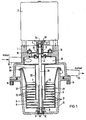
- a drive motor (electric motor) 2 with vertical drive shaft 3 is attached on the top of a pot-shaped housing part 1.
- the drive shaft 3 is cross-divided, the two shaft sections 3a, 3b formed by transverse division being connected to one another by a coupling 4.
- a rotationally symmetrical collecting container 5 serving as a centrifuge is arranged on the lower shaft section 3b in a rotationally fixed but axially detachable manner.
- the collecting container 5 has a hub 6 in the center, which allows the container to be pushed axially onto the lower shaft section 3b.
- the hub 6 is provided with a slot 7, in which a driver pin 8 which extends transversely to the longitudinal axis of symmetry engages.
- the collecting container 5 can be axially fixed by means of a locking ring 9.
- the free end 10 of the shaft section 3b is guided in a bearing 11 (DU bushing) which is fastened in a lower housing part 13 surrounding the collecting container by means of elastic means 12 (GI metal bushing).
- the lower housing part 13 is fastened to the upper housing part 1 by means of easily detachable screw elements 14.
- the upper end of the shaft section 3b is also mounted in the area of the coupling 4 with the aid of further elastic means 15 with little vibration.
- a pipe socket 20 concentrically surrounding the shaft section 3b leads from the distribution space 19 to approximately the bottom of the collecting container 5, but at least to the lower third of the container.
- the collecting container 5 has a multiplicity of partition walls 21 which run transversely to the axis of symmetry and which form a multiplicity of chambers 22, which are connected both to one another and to the container opening 24 by openings 23 arranged concentrically to the hub 6 and to the pipe socket 20.
- the openings 22 are larger than the outer diameter of the pipe socket 20 and dimensioned such that the liquid introduced into the container via the inlet duct 16 and the pipe socket can flow through the container opening 24 into the outlet duct 25 without backflow. So that the liquid cannot penetrate into the lower housing part 13, the container 5 is provided at the top with an edge 26 which overlaps the upper edge of the housing part 3.
- the partition walls 21 and the chambers 22 formed by them serve to collect the entrained solid particles, which are pressed against the peripheral walls 27 of the container as a result of centrifugal force during the rotation of the container, in a uniformly distributed manner.
- the chambers fill evenly from bottom to top during use. Depending on the container size, at least three such chambers are necessary, but advantageously about 10 to 12 with a container volume of 700 ml.
- the ratio of the partition wall to the diameter of one chamber is at least 5: 1.
- the liquid traversed with solids via the pipe socket 20 is practically introduced near the container bottom due to the relatively deep immersion of the socket in the container 5.
- the container rotates (speed about 2,500 to 3,000 rpm)
- the solid particles are centrifuged evenly distributed on the chambers 22 on the peripheral walls 27 of the container, while the liquid is pressed upwards through the openings 23 and the container opening 24 into the outlet channel 25 .
- an optical and / or acoustic signal is given as an indication for changing the container.
- the starting time of the motor can advantageously be measured or checked, e.g.
- a light barrier arrangement 28 is attached in the upper shaft section 3a and on the corresponding fixed housing part, with the aid of which the starting time of the motor can be measured until the nominal speed is reached, which ultimately depends on the moment of inertia and thus on the fill level of the container.
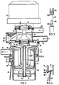
- Fig. 2 shows, also in longitudinal section, a second embodiment of a separation device according to the invention.
- a drive motor 32 is attached to the top of a housing part 31;
- the drive motor drives not only the centrifuge, but also a pump 34 mounted on the motor shaft 33.
- the pump 34 With the pump 34, the liquid sucked from a suction system from the patient's mouth and separated from air in a separating device (see also European patent 00 23 036) is fed via an inlet channel 35 into the pump housing 36, then with pressure into the centrifuge and then via the Outlet channel 37. led into the drain.
- a check valve 38 At the outlet of the pump housing 36 there is a check valve 38.
- the check valve 38 is a hemispherical plastic part which is fastened in a hinge-like manner in the pump housing. With 39 seals are designated with which the motor shaft 33 is sealed against the pump housing.
- the motor shaft 33 is cross-divided in the area of the dash-dotted circle 111 and there contains a plug-in coupling 40 shown in the exploded state in FIG enable.
- the lower shaft section 33b is part of the collecting container 41, which is constructed similarly to the collecting container 5 in FIG. 1 and also has a multiplicity of partition walls 42 running transversely to the axis of symmetry, of which only one is shown in this embodiment for the sake of clarity. Since, as already mentioned in the first embodiment, the collecting container advantageously consists of plastic and is expediently designed as a disposable item, it is advantageous to design the lower shaft section 33b and the one coupling part 40b of the coupling 40 together with the collecting container 41 as an injection molded part.
- the lower end of the shaft section 33b is mounted in a spherical slide bearing 43 which is held in the lower housing part 45 with the aid of a tension spring 44 in such a way that the collecting container 41 together with the shaft section 33b can be easily removed from the storage and reinserted therein.
- the lower housing part 45 advantageously forms part of the outlet channel 37 with the housing walls 46 and can be fastened to the upper housing part 31 by means of a bayonet catch designated 47.
- a latching device 48 which is shown in detail in FIG. 4, ensures that the lower housing part 45 is held against rotation in the closed position of the bayonet catch.
- the catch consists of a hinge-like rocker arm 49 arranged on the lower housing part 45, the short leg 49a of which engages in a notch 50 in the upper housing part 31 (dash-dotted representation).
- At least one further inlet channel 51 is provided in addition to the inlet channel 35, which is connected, for example in a known manner, to the drain of a bowl arrangement or to the drain of a water jet pump of a dental device and opens into a distribution space 52, into which the liquid coming from the pump housing is also directed.
- the pump is integrated in the upper housing part and only one drive motor is required for the pump and centrifuge, a very compact and economical separating device can be achieved.
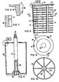
- Figures 5 to 10 show in different views and partly in section details of another embodiment of a collecting container.
- the collecting container in contrast to the embodiments according to FIGS. 1 and 2, in which the collecting container (item 5, 41) is designed as a one-part container, in the embodiment which is explained in more detail below, the collecting container consists of two parts, a cup-shaped, open at the top and essentially cylindrical container part 55 having container inner walls (FIG. 5) and an insert part 56 (FIG. 6) which can be snapped into it.
- the container part 55 has a molded-on hub 57 which, as shown in FIG. 3, can be coupled to the drive shaft of the motor in a rotationally fixed but axially releasable manner.
- the hub 57 has a bore 58 into which a stub shaft (not shown) can be inserted, which, as shown in FIG. 2, engages in a suitably designed spherical bearing (position 43 in FIG. 2).
- the container part 55 has on the bottom outside a plurality of webs or wings 59 which run in a star shape from the axis of symmetry and which, when the container rotates, generate an overpressure in the space below which prevents liquid from penetrating into this space or any liquid therein pushes up into the drain.
- the arrangement of the wings 59 can be seen from FIG. 10, which shows the container part 55 from the underside.
- the insert part 56 which is shown in FIG. 6 to the right of the axis of symmetry in the view and to the left of it in longitudinal section, consists of a multiplicity of partition walls 60 which are arranged at a uniform distance from one another and which are formed by three longitudinal webs 61 arranged on the circumference and one forming the upper edge Lid 62 are interconnected.
- the dividing walls 60 are circular, each have the same outside diameter, but different inside diameters, viewed from bottom to top, a continuously decreasing diameter. In the assembled state, this means that the openings 62 (designated by 23 in FIG. 1) between the hub 57 (shown in broken lines in FIG. 9) and the inner edges of the dividing walls 60 are greatest at the bottom of the container and steadily toward the upper edge are getting smaller.
- the opening 64 in the cover 63 is smaller than the aforementioned openings 62, which result from the continuous reduction in the inside diameter of the partition walls up to the cover. This significantly smaller opening 64 ultimately determines the degree of separation of the particles to be separated by the peripheral speed prevailing at this point during rotation.
- the inner diameter of the partition walls 60 which decreases continuously from the bottom of the container to the edge of the container, is advantageously one. Angular deviation (a) of about 5 ° from the vertical.
- the insert part 56 can be inserted in a latching manner in the container part 55, for which purpose, as shown in detail in FIGS. 7 and 8, the container part 55 contains an annular constriction 67 in the region of the upper edge, into which the insert part is placed onto the container part 55 a likewise annular bulge 68 on the cover 62 of the insert part 56 engages positively in the sense of a clamp connection.
- the two-part embodiment has the advantage that the insert part 56, which contains the centrifuged particles, contains considerably less container material (plastic) than in a one-part one Execution, so that the disposal and reprocessing of the containers is less problematic than with a one-piece design.
- the separation device described With the separation device described, a very high degree of separation can be achieved, which, depending on the size of the particles, can be 98%. With the separation of solid particles with a grain size of 10011, a degree of separation of over 95% is still achieved, with a volume flow of approximately 700 ml / min liquid throughput. Depending on the number and dimensions of the individual chambers, the collection container can hold several hundred grams of amalgam. When the chambers are full, the container is exchanged and sent to a separator for further disposal.
Description
- Die Erfindung bezieht sich auf eine Vorrichtung zum Abscheiden von Feststoffen, insbesondere Amalgam, aus Flüssigkeiten in zahnärztlichen Einrichtungen, mit einer von einem Motor angetriebenen Zentrifuge, in die über einen Einlaßkanal die mit Feststoffen angereicherte Flüssigkeit eingeleitet wird, und in der infolge Zentrifugalkraft die Feststoffe an peripheren Zentrifugenwandungen zentrifugiert werden, während die Flüssigkeit durch Überlauf aus der Zentrifuge gepreßt und in einen Abflußkanal geleitet wird, und mit einem Sammelbehälter, in dem die zentrifugierten Feststoffe gesammelt und verwahrt werden.
- Eine Vorrichtung dieser Art ist beispielsweise aus DE-A-35 21 929 bekannt.
- Nachteilig bei dieser bekannten Vorrichtung ist, daß aufgrund Adhäsion Feststoffteilchen an der Innenfläche der Zentrifuge haften bleiben. Diese Haftung ist insbesondere bei sehr kleinen Partikeln « 0,5 mm) gegeben und besteht auch dann noch, wenn die Zentrifuge zum Stillstand kommt. Um diese Partikel dennoch in den Sammelbehälter zu transportieren, wurde zwar eine Schnellabbremsung vorgesehen; wie praktische Versuche gezeigt haben, überwiegen die Adhäsionskräfte gegenüber den Abbremskräften, so daß nach wie vor noch größere Mengen dieser kleinen Partikel in der Zentrifuge verbleiben. Die bekannte Vorrichtung ist außerdem vergleichsweise aufwendig.
- Der im Anspruch 1 angegebenen Erfindung liegt die Aufgabe zugrunde, demgegenüber eine Verbesserung zu erzielen.
- Gemäß der Erfindung ist der Sammelbehälter für die Partikel Bestandteil des rotierenden Systems, bildet also mit der Rotorwelle eine kompakte, jedoch von dieser leicht trennbare Einheit. Der Sammelbehälter enthält mehrere, senkrecht zur Rotorachse angeordnete Trennwände, die übereinander angeordnete Kammern bilden. Das Verhältnis Durchmesser zur Höhe dieser Kammern beträgt wenigstens 5:1. Besonders vorteilhaft ist es, wenn konzentrisch zur Antriebswelle ein rohrförmiger Einlaufstutzen für die Flüssigkeit angeordnet ist und dieser möglichst tief, mindestens bis in das untere Drittel des Sammelbehälters, eintaucht, wozu die Trennwände entsprechend große, auch den Durchtritt der Flüssigkeit gewährleistende, konzentrische Öffnungen aufweisen. Der Sammelbehälter ist zweckmäßigerweise als Einwegbehälter ausgebildet und besteht aus umweltfreundlichem Werkstoff, z.B. aus Polypropylen oder Polysulfon. Gemäß einer vorteilhaften Weiterbildung der Erfindung ist der Antriebsmotor für die Zentrifuge gleichsam als Antriebsmotor für eine die Flüssigkeit in den Sammelbehälter drückende Pumpe vorgesehen. Letztere ist vorteilhaft im Oberteil der Zentrifuge integriert angeordnet. Das gesamte Antriebssystem ist schwingungsarm aufgehängt. Vorteilhafterweise ist hierzu die Antriebswelle quergeteilt und der den Sammelbehälter in Rotation versetzende Wellenabschnitt elastisch gelagert, wobei das eine, dem Sammelbehälter zugewandte, Lager von einem den Sammelbehälter umgebenden, becherförmigen Gehäuseunterteil aufgenommen wird. Der Füllgrad des Sammelbehälters wird vorteilhafterweise durch Messen der Anlaufzeit des Motors überwacht, wozu entsprechende, die Anlaufzeit messende Sensorelemente vorhanden sind, welche bei Überschreiten einer bestimmten, der maximalen Füllmenge des Behälters zugeordneten Anlaufzeit ein Signal für eine optische und/oder akustische Anzeige liefern.
- Weitere vorteilhafte Ausgestaltungen und Weiterbildungen der Erfindung ergeben sich aus der nachfolgenden Beschreibung mehrerer Ausführungsbeispiele der Erfindung anhand der Zeichnung.
- Es zeigen:
- Figur 1 eine erste Ausführungsform der Erfindung,
- Figur 2 eine zweite Ausführungsform der Erfindung,
- Figuren 3 und 4 Ausschnitte aus Figur 2,
- Figuren 5 bis 10 eine weitere Ausführungsform eines Sammelbehälters.
- An der Oberseite eines topfförmigen Gehäuseteils 1 ist ein Antriebsmotor (Elektromotor) 2 mit lotrechter Antriebswelle 3 befestigt. Die Antriebswelle 3 ist quergeteilt, wobei die beiden durch Querteilung gebildeten Wellenabschnitte 3a, 3b durch eine Kupplung 4 miteinander verbunden sind. Am unteren Wellenabschnitt 3b ist ein als Zentrifuge dienender rotationssymmetrischer Sammelbehälter 5 drehfest, aber axial lösbar angeordnet. Der Sammelbehälter 5 weist mittig eine Nabe 6 auf, die es erlaubt, den Behälter auf den unteren Wellenabschnitt 3b axial aufzuschieben. Im oberen Teil ist die Nabe 6 mit einem Schlitz 7 versehen, in dem ein quer zur Längssymmetrieachse verlaufender Mitnehmerstift 8 eingreift. Im aufgeschobenen Zustand kann der Sammelbehälter 5 mittels eines Feststellringes 9 axial fixiert werden. Das freie Ende 10 des Wellenabschnittes 3b ist in einem Lager 11 (DU-Buchse) geführt, welches mit Hilfe elastischer Mittel 12 (GI-Metall-Buchse) in einem den Sammelbehälter umgebenden unteren Gehäuseteil 13 befestigt ist. Das untere Gehäuseteil 13 ist mittels leicht lösbarer Schraubelemente 14 am oberen Gehäuseteil 1 befestigt. Das obere Ende des Wellenabschnittes 3b ist im Bereich der Kupplung 4 mit Hilfe weiterer elastischer Mittel 15 ebenfalls schwingungsarm gelagert. Diese stützen sich einerseits am oberen Gehäuseteil 1 und andererseits an einem Trägerteil 16 für ein weiteres Wellenlager 17 ab.
- Mit 18 ist ein Einlaufkanal bezeichnet, der in bekannter Weise mit dem saugseitigen Teil einer Absaugeinrichtung verbunden ist und über den mit Feststoff-, wie Amalgam-, Gold- etc. -partikel angereicherte Flüssigkeit in einen ringförmigen Verteilerraum 19 eintreten kann. Vom Verteilerraum 19 aus führt ein den Wellenabschnitt 3b konzentrisch umgebender Rohrstutzen 20 bis etwa in Bodennähe des Sammelbehälters 5, mindestens jedoch bis in das untere Drittel des Behälters.
- Der Sammelbehälter 5 weist eine Vielzahl von quer zur Symmetrieachse verlaufenden Trennwänden 21 auf, die eine Vielzahl von Kammern 22 bilden, welche durch konzentrisch zur Nabe 6 und zum Rohrstutzen 20 angeordnete Öffnungen 23 sowohl untereinander als auch mit der Behälteröffnung 24 verbunden sind. Die Öffnungen 22 sind größer als der äußere Durchmesser des Rohrstutzens 20 und so bemessen, daß die über den Einlaufkanal 16 und den Rohrstutzen in die Behälter eingeführte Flüssigkeit ohne Rückstau über die Behälteröffnung 24 in den Auslaßkanal 25 fließen kann. Damit die Flüssigkeit nicht in das untere Gehäuseteil 13 eindringen kann, ist der Behälter 5 oben mit einem die Oberkante des Gehäuseteils 3 übergreifenden Rand 26 versehen.
- Die Trennwände 21 und die durch sie gebildeten Kammern 22 dienen dazu, die mitgeführten Feststoffpartikel, welche während der Rotation des Behälters infolge Zentrifugalkraft gegen die peripheren Wandungen 27 des Behälters gedrückt werden, gleichmäßig verteilt aufzufangen. Wie Versuche gezeigt haben, läßt sich so eine unwuchtarme Ablagerung der zum Teil spezifisch relativ schweren (Amalgam-)Feststoffpartikel erzielen. Im Laufe der Benutzung füllen sich die Kammern gleichmäßig von unten nach oben. Je nach Behältergröße sind wenigstens drei solcher Kammern notwendig, vorteilhafterweise jedoch etwa 10 bis 12 bei einem Behältervolumen von 700 ml. Das Verhältnis Trennwand - Durchmesser zu Höhe einer Kammer beträgt mindestens 5:1.
- Die über den Rohrstutzen 20 mit Feststoffen durchsetzte Flüssigkeit wird infolge des relativ tiefen Eintauchens des Stutzens in den Behälter 5 praktisch in Nähe des Behälterbodens eingeleitet. Bei Rotation des Behälters (Drehzahl etwa 2.500 bis 3.000 Upm), werden die Feststoffpartikel gleichmäßig auf die Kammern 22 verteilt an den peripheren Wandungen 27 des Behälters zentrifugiert, während die Flüssigkeit über die Öffnungen 23 und die Behälteröffnung 24 nach oben in den Auslaßkanal 25 gedrückt wird. Sobald ein bestimmter Füllungsgrad der Feststoffpartikel erreicht ist, wird ein optisches und/oder akustisches Signal als Hinweis zum Auswechseln des Behälters gegeben. Hierzu kann vorteilhafterweise die Anlaufzeit des Motors gemessen bzw. kontrolliert werden, z.b. indem im oberen Wellenabschnitt 3a und an mit diesem korrespondierenden festen Gehäuseteil eine Lichtschrankenanordnung 28 angebracht ist, mit deren Hilfe die Anlaufzeit des Motors bis Erreichen der Nenndrehzahl, welche letztlich vom Trägheitsmoment und damit vom Füllstand des Behälters abhängig ist, gemessen werden kann. Bei Überschreiten eines vorbestimmten, einer bestimmten Füllmenge des Behälters zugeordneten Anlaufzeit kann so ein optisches und/oder akustisches Signal abgegeben und gegebenenfalls auch der Motor abgeschaltet werden.
- Die Fig. 2 zeigt, ebenfalls im Längsschnitt, eine zweite Ausführungsform einer Abscheidevorrichtung nach der Erfindung. Auch bei dieser Ausführungsform ist an der Oberseite eines Gehäuseteils 31 ein Antriebsmotor 32 befestigt; im Gegensatz zu der Ausführungsform nach Fig. 1 treibt der Antriebsmotor nicht nur die Zentrifuge, sondern auch eine auf der Motorwelle 33 aufgesetzte Pumpe 34 an. Mit der Pumpe 34 wird die von einer Absauganlage aus dem Patientenmund abgesaugte und in einer Separiereinrichtung von Luft getrennte Flüssigkeit (siehe hierzu europäisches Patent 00 23 036) über einen Einlaßkanal 35 in das Pumpengehäuse 36 geleitet, dann mit Druck in die Zentrifuge und anschließend über den Auslaßkanal 37.in den Abfluß geleitet. Am Ausgang des Pumpengehäuses 36 befindet sich ein Rückschlagventil 38. Das Rückschlagventil 38 ist ein halbkugelförmiges Kunststoffteil, welches im Pumpengehäuse scharnierartig beweglich befestigt ist. Mit 39 sind Dichtungen bezeichnet, mit denen die Motorwelle 33 gegenüber dem Pumpengehäuse abgedichtet ist.
- Die Motorwelle 33 ist im Bereich des strichpunktiert eingezeichneten Kreises 111 quergeteilt und enthält dort eine in Fig. 3 im auseinandergezogenen Zustand gezeigte Steckkupplung 40 in Form von zueinander passenden Mehrkantprofilteilen 40a, 40b, die einerseits eine Drehmomentübertragung und andererseits ein leichtes An- und Abkuppeln der Teile ermöglichen. Der untere Wellenabschnit 33b ist Bestandteil des Sammelbehälters 41, der ähnlich aufgebaut ist wie der Sammelbehälter 5 in Fig. 1 und ebenfalls eine Vielzahl von quer zur Symmetrieachse verlaufenden Trennwänden 42 aufweist, von denen der besseren Übersichtlichkeit wegen in dieser Ausführungsform nur eine einzige eingezeichnet ist. Nachdem, wie bereits bei der ersten Ausführungsform erwähnt, der Sammelbehälter vorteilhafterweise aus Kunststoff besteht und zweckmäßigerweise als Einmalartikel ausgebildet ist, ist es vorteilhaft, den unteren Wellenabschnitt 33b und das eine Kupplungsteil 40b der Kupplung 40 zusammen mit dem Sammelbehälter 41 als ein Spritzteil auszubilden.
- Das untere Ende des Wellenabschnitts 33b ist in einem kugelförmig ausgebildeten Gleitlager 43 gelagert, welches mit Hilfe einer Spannfeder 44 im Gehäuseunterteil 45 so gehaltert ist, daß der Sammelbehälter 41 zusammen mit dem Wellenabschnitt 33b leicht aus der Lagerung entnehmbar und wieder in diese einführbar ist. Das Gehäuseunterteil 45 bildet mit Gehäusewandungen 46 vorteilhafterweise einen Teil des Auslaßkanales 37 und ist mittels eines mit 47 bezeichneten Bajonettverschlusses am oberen Gehäuseteil 31 befestigbar. Eine Rasteinrichtung 48, die in Fig. 4 im Detail dargestellt ist, sorgt für eine verdrehsichere Halterung des Gehäuseunterteils 45 in der Schließstellung des Bajonettverschlusses. Die Rastung besteht aus einem scharnierartig am Gehäuseunterteil 45 angeordneten Kipphebel 49, dessen kurzer Schenkel 49a in eine Kerbe 50 des oberen Gehäuseteils 31 rastend eingreift (strichpunktierte Darstellung).
- Im Gegensatz zu der Ausführungsform nach Fig. 1 ist bei der Ausführungsform nach Fig. 2 außer dem Einlaßkanal 35 mindestens noch ein weiterer Einlaßkanal 51 vorgesehen, der beispielsweise in bekannter Weise mit dem Abfluß einer Speischalenanordnung oder mit dem Abfluß einer Wasserstrahlpumpe eines zahnärztlichen Gerätes verbunden ist und in einen Verteilerraum 52 mündet, in den auch die aus dem Pumpengehäuse kommende Flüssigkeit geleitet wird. An den Verteilerraum 52 schließt sich, wie beim Ausführungsbeispiel nach Figur 1, ein bis in Bodennähe des Sammelbehälters 41 reichender Rohrstutzen 53 an.
- Dadurch, daß die Pumpe integriert im oberen Gehäuseteil angeordnet ist, und nur ein Antriebsmotor für Pumpe und Zentrifuge benötigt wird, läßt sich eine sehr kompakte und wirtschaftliche Abscheideeinrichtung erzielen.
- Selbstverständlich können auch bei der in Fig. 2 gezeigten Anordnung die bereits zu der Ausführungsform nach Fig. 1 beschriebenen Maßnahmen zur Füllstandsmessung des Sammelbehälters mit Vorteil eingesetzt werden.
- Die Figuren 5 bis 10 zeigen in verschiedenen Ansichten und teilweise im Schnitt Einzelheiten einer weiteren Ausführungsform eines Sammelbehälters. Im Gegensatz zu den Ausführungsformen nach Figuren 1 und 2, bei denen der Sammelbehälter (Pos. 5, 41) als einteiliger Behälter ausgebildet ist, besteht bei der nachfolgend näher erläuterten Ausführungsform der Sammelbehälter aus zwei Teilen, einem becherförmigen, nach oben offenen und im wesentlichen zylindrische Behälterinnenwandungen aufweisenden Behälterteil 55 (Figur 5) und einem in diesen rastend einsetzbaren Einsatzteil 56 (Figur 6). Der Behälterteil 55 weist, wie beim Ausführungsbeispiel nach Figur 2, eine angespritzte Nabe 57 auf, die, wie in Figur 3 gezeigt, mit der Antriebswelle des Motors drehfest, axial jedoch leicht lösbar kuppelbar ist. Die Nabe 57 weist eine Bohrung 58 auf, in die ein nicht gezeigter Wellenstumpf einsetzbar ist, der, wie in Figur 2 gezeigt, in ein entsprechend ausgebildetes Kalottenlager (Position 43 in Fig. 2) eingreift. Der Behälterteil 55 weist bodenseitig außen mehrere sternförmig von der Symmetrieachse verlaufende Stege bzw. Flügel 59 auf, die bei Rotation des Behälters in dem darunter befindlichen Raum einen Überdruck erzeugen, der verhindert, daß Flüssigkeit in diesen Raum eindringen kann bzw. evtl. darin befindliche Flüssigkeit nach oben in den Abfluß wegdrückt. Die Anordnung der Flügel 59 ist aus Figur 10 ersichtlich, die das Behälterteil 55 von der Unterseite her zeigt.
- Das Einsatzteil 56, welches in Figur 6 rechts von der Symmetrieachse in der Ansicht und links davon im Längsschnitt gezeigt ist, besteht aus einer Vielzahl von in gleichmäßigem Abstand voneinander angeordneten Trennwänden 60, die durch drei am Umfang angeordnete Längsstege 61 und einem den oberen Rand bildenden Deckel 62 miteinander verbunden sind. Die Trennwände 60 sind kreisringförmig ausgebildet, haben jeweils gleichen Außendurchmesser, jedoch verschiedenen Innendurchmesser, und zwar von unten nach oben betrachtet einen kontinuierlich kleiner werdenden Durchmesser. Hieraus ergibt sich im montierten Zustand, daß die zwischen der Nabe 57 (in Fig. 9 gestrichelt eingezeichnet) und den Innenkanten der Trennwände 60 gebildeten Öffnungen 62 (in Figur 1 mit 23 bezeichnet) in Bodennähe des Behälters am größten und zum oberen Rand hin stetig kleiner werdend sind. Die im Deckel 63 vorhandene Öffnung 64 ist kleiner als die vorgenannten Öffnungen 62, die sich aus der kontinuierlichen Verkleinerung des Innendurchmessers der Trennwände bis zum Deckel ergeben. Diese deutlich kleinere Öffnung 64 bestimmt durch die an dieser Stelle herrschende Umfangsgeschwindigkeit bei Rotation letztlich den Abscheidegrad der abzuscheidenden Partikel. Der sich vom Behälterboden bis zum Behälterrand kontinuierlich verkleinernde Innendurchmesser der Trennwände 60 liegt vorteilhafterweise bei einer. Winkelabweichung (a) von etwa 5° von der Vertikalen.
- Das Einsatzteil 56 ist, wie bereits erwähnt, im Behälterteil 55 rastend einsetzbar, wozu, wie in Figuren 7 und 8 als Einzelheit dargestellt, das Behälterteil 55 im Bereich der Oberkante eine ringförmige Einschnürung 67 enthält, in die bei Aufsetzen des Einsatzteils auf den Behälterteil 55 eine ebenfalls ringförmige Ausbauchung 68 am Deckel 62 des Einsatzteils 56 formschlüssig im Sinne einer Klemmverbindung eingreift.
- Wenngleich auch bei dieser, wie bei den zuvor beschriebenen, Ausführungsformen der gesamte Sammelbehälter als einmal verwendbarer Behälter vorgesehen ist, so hat die zweiteilige Ausführung den Vorteil, daß das mit den zentrifugierten Partikein behaftete Einsatzteil 56 erheblich weniger Behältermaterial (Kunststoff) enthält als bei einer einteiligen Ausführung, so daß die Entsorgung und Wiederaufbereitung der Behälter weniger problematisch ist als bei einer einteiligen Ausführung.
- Mit der beschriebenen Abscheideeinrichtung läßt sich ein sehr hohes Abscheidegrad erzielen, der, je nach Größe der Partikel, bei 98 % liegen kann. Bei Abscheidung von Feststoffteilchen einer Korngröße von 10011 wird noch ein Abscheidegrad von über 95 % erzielt, bei einem Volumenstrom von etwa 700 ml/min Flüssigkeitsdurchsatz. Je nach Anzahl und Abmessungen der einzelnen Kammern kann der Sammelbehälter mehrere hundert Gramm Amalgam aufnehmen. Bei gefüllten Kammern wird der Behälter ausgetauscht und zur weiteren Entsorgung einer Abscheideanstalt zugeführt.
- Obwohl es zweckmäßig und vorteilhaft ist, die Behälteranordnung unterhalb des Motors vorzusehen, ist auch eine umgekehrte Anordnung denkbar, bei der der Motor unten und darüber der Sammelbehälter angeordnet sind.
Claims (15)
Applications Claiming Priority (4)
| Application Number | Priority Date | Filing Date | Title |
|---|---|---|---|
| DE3716008 | 1987-05-13 | ||
| DE3716008 | 1987-05-13 | ||
| DE3724841 | 1987-07-27 | ||
| DE3724841 | 1987-07-27 |
Publications (2)
| Publication Number | Publication Date |
|---|---|
| EP0290745A1 EP0290745A1 (de) | 1988-11-17 |
| EP0290745B1 true EP0290745B1 (de) | 1990-07-18 |
Family
ID=25855545
Family Applications (1)
| Application Number | Title | Priority Date | Filing Date |
|---|---|---|---|
| EP88104030A Expired - Lifetime EP0290745B1 (de) | 1987-05-13 | 1988-03-14 | Vorrichtung zum Abscheiden von Feststoffen aus Flüssigkeiten in zahnärztlichen Einrichtungen |
Country Status (4)
| Country | Link |
|---|---|
| US (1) | US4891041A (de) |
| EP (1) | EP0290745B1 (de) |
| JP (1) | JPH0517051Y2 (de) |
| DE (1) | DE3860326D1 (de) |
Cited By (1)
| Publication number | Priority date | Publication date | Assignee | Title |
|---|---|---|---|---|
| WO2022090553A3 (de) * | 2020-11-02 | 2022-07-07 | Bruno Pregenzer | Abscheider mit herausnehmbarem zentrifugenbehälter |
Families Citing this family (18)
| Publication number | Priority date | Publication date | Assignee | Title |
|---|---|---|---|---|
| DE4104593A1 (de) * | 1991-02-14 | 1992-08-20 | Siemens Ag | Ventilanordnung in einer zahnaerztlichen absauganlage |
| JP2725127B2 (ja) * | 1992-11-26 | 1998-03-09 | 三栄技研株式会社 | 歯科治療汚物の廃水処理装置 |
| US6579218B1 (en) | 1998-09-25 | 2003-06-17 | Analytical Engineering, Inc. | Centrifugal filter utilizing a partial vacuum condition to effect reduced air drag on the centrifuge rotor |
| US6517475B1 (en) * | 1998-09-25 | 2003-02-11 | Baldwin Filters, Inc. | Centrifugal filter for removing soot from engine oil |
| US6261455B1 (en) | 1998-10-21 | 2001-07-17 | Baldwin Filters, Inc. | Centrifuge cartridge for removing soot from oil in vehicle engine applications |
| US6213929B1 (en) * | 1998-09-25 | 2001-04-10 | Analytical Engineering, Inc. | Motor driven centrifugal filter |
| US6520902B1 (en) | 1998-10-21 | 2003-02-18 | Baldwin Filters, Inc. | Centrifuge cartridge for removing soot from engine oil |
| US6428700B1 (en) | 2000-09-06 | 2002-08-06 | Baldwin Filters, Inc. | Disposable centrifuge cartridge backed up by reusable cartridge casing in a centrifugal filter for removing soot from engine oil |
| US6929596B2 (en) * | 2003-02-07 | 2005-08-16 | Fleetguard, Inc. | Centrifuge with separate hero turbine |
| DE102006014682B4 (de) * | 2006-03-28 | 2017-02-02 | DüRR DENTAL AG | Saugmaschine |
| CA2667380C (en) * | 2006-10-23 | 2015-03-31 | Steven A. Mcalister | Centrifugal concentrator |
| DE102006058955B4 (de) * | 2006-12-12 | 2014-07-24 | DüRR DENTAL AG | Saugvorrichtung für dentale, medizinische und industrielle Zwecke |
| AT505538B1 (de) * | 2007-07-27 | 2009-02-15 | Pregenzer Bruno | Abscheider zum abscheiden von luft und feststoffen aus einem zahnärztlichen abwassergemisch |
| CA2770039C (en) * | 2009-07-29 | 2014-12-02 | Flsmidth A/S | Centrifugal bowl with liner material molded on a frame |
| CA2877520A1 (en) | 2012-06-15 | 2013-12-19 | 650438 Alberta Ltd. | Method and system for separation of suspensions |
| US10695774B2 (en) * | 2017-11-21 | 2020-06-30 | Richard F Corbus | Centrifuge separator for gold mining and recovery |
| MX2020010385A (es) * | 2018-04-04 | 2021-01-08 | Jody G Robbins | Separación de minerales por gravedad específica. |
| CN108993306B (zh) * | 2018-08-13 | 2021-06-25 | 苏州卓诚钛设备有限公司 | 一种内锁紧拆装式的同轴旋转药液搅拌装置 |
Family Cites Families (16)
| Publication number | Priority date | Publication date | Assignee | Title |
|---|---|---|---|---|
| US1828096A (en) * | 1929-06-14 | 1931-10-20 | Tandy A Bryson | Centrifugal process and mechanism |
| US1924676A (en) * | 1930-05-16 | 1933-08-29 | Wahl Clipper Corp | Hair clippers |
| US1981924A (en) * | 1931-06-06 | 1934-11-27 | American Laundry Mach Co | Paper pulp extractor |
| US2353983A (en) * | 1937-03-10 | 1944-07-18 | Banning Hellmuth | Purification of pulp |
| US2140388A (en) * | 1937-05-24 | 1938-12-13 | Paul J Lucas | Oil filter |
| US2213107A (en) * | 1938-11-28 | 1940-08-27 | Research Corp | Ultracentrifuge |
| CH238684A (de) * | 1944-04-06 | 1945-08-15 | W Weiland Carl | Zentrifuge zum Reinigen von Flüssigkeiten. |
| GB951388A (en) * | 1962-04-11 | 1964-03-04 | Mixing And Separating Equipmen | Improvements in or relating to machines for cleaning or clarifying contaminated liquids |
| FR1380872A (fr) * | 1963-12-31 | 1964-12-04 | Knecht Filterwerke Gmbh | Dispositif pour l'épuration d'une huile de graissage |
| GB1507742A (en) * | 1976-06-25 | 1978-04-19 | Glacier Metal Co Ltd | Centrifugal filters |
| US4140270A (en) * | 1977-11-07 | 1979-02-20 | Western Dairy Products | Centrifugal separator for food products |
| DE2929804C2 (de) * | 1979-07-23 | 1985-10-03 | Siemens AG, 1000 Berlin und 8000 München | Zahnärztliche Absaugeinrichtung |
| SE440071B (sv) * | 1979-08-17 | 1985-07-15 | Scania Dental | Apparat av centrifugtyp for avskiljning av fasta partiklar fran avfallsvatten |
| SE442829B (sv) * | 1984-06-20 | 1986-02-03 | Scania Dental | Apparat for att separera luft och fasta partiklar fran en vetska |
| ATE69151T1 (de) * | 1984-12-17 | 1991-11-15 | Werner Trawoeger | Verfahren zur trennung eines dentalen feststoff- fluessigkeitgemisches. |
| DE3542115A1 (de) * | 1985-11-28 | 1987-06-04 | Duerr Dental Gmbh Co Kg | Vollmantel-zentrifuge zum abscheiden feiner feststoffpartikel aus abwasser |
-
1988
- 1988-03-14 EP EP88104030A patent/EP0290745B1/de not_active Expired - Lifetime
- 1988-03-14 DE DE8888104030T patent/DE3860326D1/de not_active Expired - Lifetime
- 1988-05-09 JP JP1988061032U patent/JPH0517051Y2/ja not_active Expired - Lifetime
- 1988-05-12 US US07/192,938 patent/US4891041A/en not_active Expired - Fee Related
Cited By (1)
| Publication number | Priority date | Publication date | Assignee | Title |
|---|---|---|---|---|
| WO2022090553A3 (de) * | 2020-11-02 | 2022-07-07 | Bruno Pregenzer | Abscheider mit herausnehmbarem zentrifugenbehälter |
Also Published As
| Publication number | Publication date |
|---|---|
| EP0290745A1 (de) | 1988-11-17 |
| JPS63180015U (de) | 1988-11-21 |
| JPH0517051Y2 (de) | 1993-05-07 |
| US4891041A (en) | 1990-01-02 |
| DE3860326D1 (de) | 1990-08-23 |
Similar Documents
| Publication | Publication Date | Title |
|---|---|---|
| EP0290745B1 (de) | Vorrichtung zum Abscheiden von Feststoffen aus Flüssigkeiten in zahnärztlichen Einrichtungen | |
| DE2439392C2 (de) | Flüssigkeitsabsaug- und Sammelvorrichtung | |
| DE2425165C2 (de) | ||
| DE69731464T2 (de) | Ambulante, mikroprozessorgesteuerte volumetrische einwegpumpe | |
| DE2835362C3 (de) | Vorrichtung zur Konditionierung einer Flüssigkeit in Analysezellen | |
| DE3601254C2 (de) | Zahnärztliche Absaugeinrichtung | |
| EP0852150B1 (de) | Blut-Gas-Trennvorrichtung | |
| EP0400431B1 (de) | Abscheideeinheit | |
| DE2200730C3 (de) | Einrichtung zum Abmessen und Verteilen einer Vielzahl von kleinen Flüssigkeitsmengen | |
| AT393669B (de) | Vorrichtung zum abscheiden feiner feststoffpartikel aus abwasser | |
| EP0300439B1 (de) | Vorrichtung zum Abscheiden von feinen Feststoffpartikeln | |
| EP0680289A1 (de) | Flüssigkeits-abscheideeinheit | |
| DE3633494C2 (de) | Vorrichtung zum Abscheiden von feinen Feststoffpartikeln, insbesondere Amalgampartikeln, aus Abwasser | |
| EP0345527B1 (de) | Ansaughilfe zur Flüssigkeitsentnahme aus einem Gefäss | |
| WO2005104987A1 (de) | Sedimentpegelfühler | |
| EP0224232A2 (de) | Vollmantel-Zentrifuge zum Abscheiden feiner Feststoffpartikel | |
| DE3820271C2 (de) | ||
| DE69830042T2 (de) | Filter mit Druckventil zum Abscheiden von Öl aus Luft für Druckluftbeschaffungsanlagen | |
| DE2545283A1 (de) | Verfahren und vorrichtung zur behandlung biologischen materials | |
| DE2657030C3 (de) | Druckfiltrationszelle | |
| WO2023148273A1 (de) | AUFFANGVORRICHTUNG FÜR EINE REAKTIONSGEFÄßEINHEIT UND REAKTIONSGEFÄßEINHEIT | |
| DE10139026A1 (de) | Feststoff-Abscheidegerät | |
| DE2333809B2 (de) | Verfahren zur Analyse von Flüssigkeitsproben für eine elektrochemisch meßbare Substanz und Vorrichtung zur Durchführung des Verfahrens | |
| DE4102695A1 (de) | Feststoff-abscheidevorrichtung | |
| EP1285636B1 (de) | Abscheidegerät |
Legal Events
| Date | Code | Title | Description |
|---|---|---|---|
| PUAI | Public reference made under article 153(3) epc to a published international application that has entered the european phase |
Free format text: ORIGINAL CODE: 0009012 |
|
| AK | Designated contracting states |
Kind code of ref document: A1 Designated state(s): DE FR GB IT SE |
|
| 17P | Request for examination filed |
Effective date: 19881207 |
|
| 17Q | First examination report despatched |
Effective date: 19891214 |
|
| GRAA | (expected) grant |
Free format text: ORIGINAL CODE: 0009210 |
|
| AK | Designated contracting states |
Kind code of ref document: B1 Designated state(s): DE FR GB IT SE |
|
| GBT | Gb: translation of ep patent filed (gb section 77(6)(a)/1977) | ||
| REF | Corresponds to: |
Ref document number: 3860326 Country of ref document: DE Date of ref document: 19900823 |
|
| ET | Fr: translation filed | ||
| ITF | It: translation for a ep patent filed |
Owner name: STUDIO JAUMANN |
|
| PLBE | No opposition filed within time limit |
Free format text: ORIGINAL CODE: 0009261 |
|
| STAA | Information on the status of an ep patent application or granted ep patent |
Free format text: STATUS: NO OPPOSITION FILED WITHIN TIME LIMIT |
|
| 26N | No opposition filed | ||
| PGFP | Annual fee paid to national office [announced via postgrant information from national office to epo] |
Ref country code: GB Payment date: 19920228 Year of fee payment: 5 |
|
| ITTA | It: last paid annual fee | ||
| PG25 | Lapsed in a contracting state [announced via postgrant information from national office to epo] |
Ref country code: GB Effective date: 19930314 |
|
| GBPC | Gb: european patent ceased through non-payment of renewal fee |
Effective date: 19930314 |
|
| EAL | Se: european patent in force in sweden |
Ref document number: 88104030.7 |
|
| REG | Reference to a national code |
Ref country code: FR Ref legal event code: TP |
|
| PGFP | Annual fee paid to national office [announced via postgrant information from national office to epo] |
Ref country code: FR Payment date: 20020322 Year of fee payment: 15 |
|
| PGFP | Annual fee paid to national office [announced via postgrant information from national office to epo] |
Ref country code: SE Payment date: 20020402 Year of fee payment: 15 Ref country code: DE Payment date: 20020402 Year of fee payment: 15 |
|
| PG25 | Lapsed in a contracting state [announced via postgrant information from national office to epo] |
Ref country code: SE Free format text: LAPSE BECAUSE OF NON-PAYMENT OF DUE FEES Effective date: 20030315 |
|
| PG25 | Lapsed in a contracting state [announced via postgrant information from national office to epo] |
Ref country code: DE Free format text: LAPSE BECAUSE OF NON-PAYMENT OF DUE FEES Effective date: 20031001 |
|
| EUG | Se: european patent has lapsed | ||
| PG25 | Lapsed in a contracting state [announced via postgrant information from national office to epo] |
Ref country code: FR Free format text: LAPSE BECAUSE OF NON-PAYMENT OF DUE FEES Effective date: 20031127 |
|
| REG | Reference to a national code |
Ref country code: FR Ref legal event code: ST |
|
| PG25 | Lapsed in a contracting state [announced via postgrant information from national office to epo] |
Ref country code: IT Free format text: LAPSE BECAUSE OF NON-PAYMENT OF DUE FEES;WARNING: LAPSES OF ITALIAN PATENTS WITH EFFECTIVE DATE BEFORE 2007 MAY HAVE OCCURRED AT ANY TIME BEFORE 2007. THE CORRECT EFFECTIVE DATE MAY BE DIFFERENT FROM THE ONE RECORDED. Effective date: 20050314 |