EP0290356A1 - Foldable goblet with a tamper-proof device - Google Patents
Foldable goblet with a tamper-proof device Download PDFInfo
- Publication number
- EP0290356A1 EP0290356A1 EP88420138A EP88420138A EP0290356A1 EP 0290356 A1 EP0290356 A1 EP 0290356A1 EP 88420138 A EP88420138 A EP 88420138A EP 88420138 A EP88420138 A EP 88420138A EP 0290356 A1 EP0290356 A1 EP 0290356A1
- Authority
- EP
- European Patent Office
- Prior art keywords
- cup
- edge
- creasing
- bag
- foldable
- Prior art date
- Legal status (The legal status is an assumption and is not a legal conclusion. Google has not performed a legal analysis and makes no representation as to the accuracy of the status listed.)
- Granted
Links
Images

Classifications
-
- A—HUMAN NECESSITIES
- A45—HAND OR TRAVELLING ARTICLES
- A45F—TRAVELLING OR CAMP EQUIPMENT: SACKS OR PACKS CARRIED ON THE BODY
- A45F3/00—Travelling or camp articles; Sacks or packs carried on the body
- A45F3/16—Water-bottles; Mess-tins; Cups
- A45F3/20—Water-bottles; Mess-tins; Cups of flexible material; Collapsible or stackable cups
-
- B—PERFORMING OPERATIONS; TRANSPORTING
- B65—CONVEYING; PACKING; STORING; HANDLING THIN OR FILAMENTARY MATERIAL
- B65D—CONTAINERS FOR STORAGE OR TRANSPORT OF ARTICLES OR MATERIALS, e.g. BAGS, BARRELS, BOTTLES, BOXES, CANS, CARTONS, CRATES, DRUMS, JARS, TANKS, HOPPERS, FORWARDING CONTAINERS; ACCESSORIES, CLOSURES, OR FITTINGS THEREFOR; PACKAGING ELEMENTS; PACKAGES
- B65D5/00—Rigid or semi-rigid containers of polygonal cross-section, e.g. boxes, cartons or trays, formed by folding or erecting one or more blanks made of paper
- B65D5/36—Rigid or semi-rigid containers of polygonal cross-section, e.g. boxes, cartons or trays, formed by folding or erecting one or more blanks made of paper specially constructed to allow collapsing and re-erecting without disengagement of side or bottom connections
-
- B—PERFORMING OPERATIONS; TRANSPORTING
- B65—CONVEYING; PACKING; STORING; HANDLING THIN OR FILAMENTARY MATERIAL
- B65D—CONTAINERS FOR STORAGE OR TRANSPORT OF ARTICLES OR MATERIALS, e.g. BAGS, BARRELS, BOTTLES, BOXES, CANS, CARTONS, CRATES, DRUMS, JARS, TANKS, HOPPERS, FORWARDING CONTAINERS; ACCESSORIES, CLOSURES, OR FITTINGS THEREFOR; PACKAGING ELEMENTS; PACKAGES
- B65D75/00—Packages comprising articles or materials partially or wholly enclosed in strips, sheets, blanks, tubes, or webs of flexible sheet material, e.g. in folded wrappers
- B65D75/04—Articles or materials wholly enclosed in single sheets or wrapper blanks
- B65D75/20—Articles or materials wholly enclosed in single sheets or wrapper blanks in sheets or blanks doubled around contents and having their opposed free margins united, e.g. by pressure-sensitive adhesive, crimping, heat-sealing, or welding
Definitions
- the invention relates to a collapsible container for liquid provided with a tamper-evident device.
- disposable cups The use of disposable cups has grown rapidly in recent years, particularly with vending machines and fast food.
- the disposable cups generally frustoconical in shape, are delivered stacked one inside the other to save space. They are made of thermoformed or injected plastic, or waxed cardboard. They are, most often stacked empty, and they are taken one by one to fill them with a liquid.
- cups that contain a freeze-dried product in their bottom just add cold or hot water, as the case may be, to obtain a specific drink.
- the lyophilized product is protected either by the upper cup or by a tamper-evident device produced by a peelable film fixed in the vicinity of the bottom of the cup.
- the container, object of the invention which we will describe below, provides a solution to these problems, while remaining very economical for the user, because it uses continuous processes for its manufacture.
- the bag is therefore composed of two walls (1) and (2) Fig. 1, of symmetrical shape with respect to the plane (6), preferably rectangular, semi-rigid, superimposed, interconnected by their edge along the four sides Fig. 2.
- the connection is made in such a way that it is liquid tight. This can be achieved by using, for example, one of the many techniques available on the market for the manufacture of flexible bags. For example, we have shown the bottom link (9) Fig 1 and 2 as being obtained by folding the starting sheet. Depending on the technique of forming the bags, up to two connections can be obtained by folding. In this case we have a preference for this solution with regard to the bottom (9) because it facilitates its forming.
- the lower part (7) Fig. 2 has a groove (3), formed mainly of a convex curve relative to the upper part of the bag, starting from one of the corners (8) of the base (9), of the bag, to go to the other corner (10) of the same base (9).
- the corners (8) and (10) are at the meeting point of the base (9) and the internal edge of the welds.
- This creasing (3) creates by folding a concave bottom (11) Fig.3 which, when formed, gives a convex shape to the side walls (12) and keeps them apart.
- the convex curve (3) is symmetrical with respect to the longitudinal axis (23).
- the upper part has a precut (5) extending substantially from the middle (18) on one side (19) to go to the other side (20) by describing a curve (5) constituting a tongue (22) of generally substantially trapezoidal shape, but the end (21) of which has a rectilinear part parallel to the lower side (9).
- the tongue (22) is preferably symmetrical with respect to the longitudinal axis (23).
- a median rectilinear groove (4) joins the starting point (18) and ending point (24) of the precut; it is parallel to the straight end part (21) of the tongue (22) and at a distance (25) equal to or greater than the distance (26) from the creasing at the angles (8) and (10) of the base d 'where the convex creasing (3) leaves optionally increased by the width of the bottom weld (9) when it is not obtained by folding.
- a bag comprising the precut (5) and the grooves (3) and (4) described, it can be unfolded as follows:
- the bag is opened by separating the pre-cut parts according to the pre-cut (5) Fig. 2, which constitutes inviolability.
- the two tabs (22) are folded outwards according to the arrows (27), making a folding along the middle grooves (4).
- the extreme rectilinear part (21) Fig. 5 of the tongues (22) is located substantially at height and parallel to the lower side (9), when the tongues (22) are completely folded down.
- the walls (30) and (31) are moved aside, along the arrows (28), in line with the folding formed by the central creasing (4) and the arrows (29) are pressed simultaneously on the base (9).
- the walls (30) and (31) are curved Fig. 6 by taking a convex ruled shape resembling a channel tile on which are pressed the tabs (22) which take the same shape.
- the angles (8) and (10) of the base are protruding and can constitute two support points, which is not enough to ensure balance; on their side, the lateral tabs (22), in the form of tiles, constitute, by their end (21) two support lines, perpendicular to the generatrices of the adjusted surface, situated in the same plane (33) substantially perpendicular to the 'axis of symmetry (44) of the container.
- the support lines define a stable support polygon for the container.
- the two support points formed by the base angles (8) and (10) can be in this plane (33), but it is preferable that they are slightly above so as not to disturb the support of the tongues ( 22). All of these supports, by their arrangement, constitute a stable base for the container. Given their number, it is obvious that the totality of the support points cannot bear simultaneously; on the other hand, when the container is full, the load causes deformations which make the supports effective.
- the shape of the convex line (34) Fig. 7 of the creasing used to delimit the bottom (35) may have a curvature varying continuously or discontinuously (36). These discontinuities (36) cause discontinuities in the curvature of the side walls which should be favored by appropriate grooves (37), parallel to the lateral sides (19) and (20). Grooves (40) should also appear on the tabs (39). They have the advantage of forming on the side walls (43) Fig. 8 edges (41) on which the edges (42) of the tongues (39) come to rest, when they are folded down, which increases the resistance buckling under load of the assembly.
- the sachet is preferably made from a sheet of a complex comprising, in particular a layer of paper and one or more layers of plastic.
- the paper layer provides rigidity, while the plastic layer (s) seal through the wall and the welds.
- a layer of plastic is generally used to line the inside of the bag: it is usually polyethylene or polypropylene.
- more elaborate complexes can be used depending on the content and climatic distribution conditions, and the composition is not limiting. It is thus possible to use a complex comprising a metallized polish-ice sheet to limit heat loss by radiation. It will be noted that the fact of starting from a sheet for the realization of the Goblet opens up very wide possibilities for matching the performance to the needs.
- connection (9) Fig.2 is obtained by folding while the connections (19) (20) and (49) are flesh-to-flesh welds.
- This way of proceeding makes it possible to eliminate the extra thicknesses linked to the median welds, situated at the level of the axis (23) in order to obtain the connections (19) and (20) by folding, but often lead to leaks. , and allows to have a sachet bottom (9) without welding, which facilitates the shaping of the bottom.
- the side welds can be widened to make handles.
- the transverse weld (51) Fig.8) we can obtain, at the side seals of the bag, a flat area with a double thickness of complex that can be cut to form a handle that will grip the container without getting burned if it contains a hot liquid.
- the tongues (22) Fig. 6 constitute gripping zones thermally insulated by the presence of a double wall separated by an air space with the possibility of adding metallized components to it as indicated above. , and that these areas are perfectly placed to naturally grasp the cup to drink its contents.
- the tongue (22) serves to guarantee the cleanliness of the edge of the container, since it is, before opening and folding, protected inside the bag.
- the lateral welds (19) and (20) Fig. 6 have, when the container is unfolded, an upper edge (52) and (53) relatively rigid, obtained by the detachment of the pre-cut part external to the tongues.
- These edges (52) and (53) can serve as a guide for the container when it is presented under a source of liquid to fill it, in order to guarantee the correct positioning of the cup and allow triggering of the filling by action on one or more micro-contacts while the filling spout protruding inside the cup in alignment with the micro-contacts forms an obstacle to their accidental actuation, for example by a simple sheet of cardboard.
- the advantage of delivering the container in the form of a fully closed sachet lies in the fact that it can be stored there, either directly freeze-dried products to the extent that the precuts are sufficiently tight, or sachets which contain them; for example, you can simultaneously put a sachet of freeze-dried coffee, a sachet of sugar, a sachet of powdered or concentrated milk and a small spoon. Thus, the user can, as desired, use all or part of these sachets. In another case, you can put a dose of toothpaste in a sachet and a toothbrush or a toothpick. As we have already specified, the closed sachet can be kept individually sterile, which is a decisive advantage compared to the cup whose sterility can only be guaranteed at the grouping level.
- the upper half has the folding tabs (22), the lower half comprises the grooves (3) and (4), two lateral welds (45) and (46) connecting the two walls and a bottom weld (9) which is a simple folding in one of the preferred versions of the invention. They are easier to implement since there is no inviolability to remove and we can in some cases prefer this solution.
- edge (78) Fig.6 for drinking which is formed by the folded tongue (22), is located so that naturally we try to wear the cup to the lips by grabbing it at right tabs (22). This way of grasping the cup is not reassuring for the user because it tends to bring his walls (12) Fig.3 that we had moved apart thanks to the concave bottom (11).
- you tighten the cup too much in your fingers you risk seeing the bottom (11) unlock, the edges come closer, the volume decrease, and the liquid overflow.
- the cup by leaning on the side edges (52) and (53) Fig.6 located on either side of the tabs (22), which has the advantage of causing when we tighten too much fingers increase in volume.
- a substantially horizontal slot (59) is made in the tongue (54), starting from an edge of the tongue (54) situated below the highest point of the convex curve (58) delimiting the bottom. concave (56). This slit is continued until its end arrives at the level (60) of the said convex curve (58). Then folded, in a fold (61) substantially perpendicular to the edge (62) of the cup, a panel (63) delimited by the lower edge (64) of said slot (59) and the end (65) of the tongue (54), so that this panel (63) passes under the concave bottom (56) and allows it to be used support to the latter.
- the shape of the slot (59) and its position depends directly on the shape of the concave bottom (56), particularly the angle (66) that the panel (63) makes when folded as indicated above so that it effectively serve as support at the bottom. It is in fact important that the folded panel (63) conforms as well as possible to the shape of the bottom, and forms with it an angle as close as possible to the right angle so as to be able to bend over it when it is subjected a pressure, instead of sliding, which would cancel its action.
- the bottom is obtained from a polygonal curve (67) Fig. 11, the highest part of which is a straight line (68) parallel to the edge (69) of the cup, the slot (70) is located at the height of this segment (68) when the tongue (54) is folded down, it is straight and parallel to the latter.
- each of the corresponding tongues (54) a trihedron coming to consolidate the support on the ground of the tongue (54), by increasing its resistance to buckling.
- the area formed by these trihedrons is a very favorable area for gripping, because when the fingers are supported in this area (57), they tend to tilt the tongue (54) inward, and the panels (63) tend to tilt in turn to come and arch on the part (74) of the bottom (56) which is parallel to the edge (62) of the cup thus ensuring its locking.
- this zone is distant from the walls (55) of the cup by a sufficient distance to be insensitive to the heat transmitted by a hot and even boiling liquid.
Abstract
Description
L'invention concerne un récipient pour liquide, pliable, muni d'un dispositif d'inviolabilité.The invention relates to a collapsible container for liquid provided with a tamper-evident device.
L'emploi des gobelets jetables s'est développé rapidement ces dernières années, notamment avec les distributeurs automatiques et la restauration rapide. Les gobelets jetables, de forme généralement tronconique, sont livrés empilés les uns dans les autres pour gagner de la place. Ils sont en matière plastique thermoformée ou injectée, ou en carton paraffiné. Ils sont, le plus souvent empilés vides, et on les prélève un à un pour les remplir d'un liquide. On trouve aussi des gobelets qui contiennent dans leur fond un produit lyophillisé : il suffit de rajouter de l'eau froide ou chaude, suivant le cas, pour obtenir une boisson spécifique. La protection du produit lyophillisé est assurée, soit par le gobelet supérieur, soit par un dispositif d'inviolabilité réalisé par une pellicule pelable fixée au voisinage du fond du gobelet. Si ces produits sont parfaitement adaptés dans les distributeurs où les conditions de stockage sont idéales et les accessoires tels que sucre ou petite cuiller sont disponibles, il n'en est pas de même dès que l'emballage devient ambulatoire. Les gobelets empilés forment un cylindre encombrant et fragile qui craint les chocs et les contraintes. Leur protection contre les souillures n'est pas facile et il n'est pas envisageable d'en avoir dans ses poches. Leur usage implique d'avoir le sucre et les cuillers à part car il n'est pas facile de les intégrer au gobelet.The use of disposable cups has grown rapidly in recent years, particularly with vending machines and fast food. The disposable cups, generally frustoconical in shape, are delivered stacked one inside the other to save space. They are made of thermoformed or injected plastic, or waxed cardboard. They are, most often stacked empty, and they are taken one by one to fill them with a liquid. There are also cups that contain a freeze-dried product in their bottom: just add cold or hot water, as the case may be, to obtain a specific drink. The lyophilized product is protected either by the upper cup or by a tamper-evident device produced by a peelable film fixed in the vicinity of the bottom of the cup. If these products are perfectly suited in distributors where the storage conditions are ideal and accessories such as sugar or teaspoon are available, it is not the same as soon as the packaging becomes ambulatory. The stacked cups form a bulky and fragile cylinder which fears shocks and stresses. Their protection against soiling is not easy and it is not possible to have it in your pocket. Their use implies having sugar and spoons apart because it is not easy to integrate them into the cup.
Le récipient, objet de l'invention, que nous allons décrire ci-dessous, apporte une solution à ces problèmes, tout en restant très économique pour l'usager, parce qu'il utilise pour sa fabrication des procédés continus.The container, object of the invention, which we will describe below, provides a solution to these problems, while remaining very economical for the user, because it uses continuous processes for its manufacture.
Il se présente, avant dépliage, sous forme d'un sachet rectangulaire, fermé sur ses quatre côtés. Nous présenterons plus loin la façon d'obtenir le sachet fermé. Nous supposons que le sachet est vide, pour les explications, mais en fait, il pourra contenir les ingrédients nécessaires à la confection d'une boisson ou tout autre produit tel que dentifrice et brosse à dents, qui seront introduits avant fermeture.
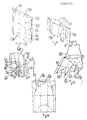
- La figure 1 représente le sachet avant fermeture avec ses rainages et ses prédécoupes.
- La figure 2 représente le même sachet après fermeture.
- La figure 3 représente le fond concave (11) du gobelet et ses liaisons avec les parois latérales (12).
- La figure 4 représente le même sachet après déchirage de la partie prédécoupée, pour former les languettes du gobelet. Cette figure représente aussi le gobelet prêt à être déplié.
- La figure 5 représente le gobelet avec les languettes rabattues, avant formage de la cavité.
- La figure 6 représente le même gobelet après formage de la cavité, en situation d'utilisation.
- La figure 7 représente un sachet avec les rainages correspondant à une courbe convexe (34) de fond dont la courbure comporte des discontinuités.
- La figure 8 représente un gobelet ouvert correspondant au sachet précédent , muni à titre indicatif d'une poignée de manutention.
- La Fig.10 représente le gobelet ouvert avec le système de verrouillage en place vu par dessous.
- La Fig.11 représente le gobelet en cours d'ouverture avec le fond non positionné.
- La Fig.12 représente le sachet-gobelet avant ouverture du sachet.
- Figure 1 shows the bag before closing with its creases and its precuts.
- Figure 2 shows the same bag after closing.
- Figure 3 shows the concave bottom (11) of the cup and its connections with the side walls (12).
- Figure 4 shows the same bag after tearing the pre-cut part, to form the tongues of the cup. This figure also shows the cup ready to be unfolded.
- Figure 5 shows the cup with the folded tabs, before forming the cavity.
- Figure 6 shows the same cup after forming the cavity, in use.
- FIG. 7 represents a bag with the grooves corresponding to a convex curve (34) at the bottom, the curvature of which comprises discontinuities.
- FIG. 8 represents an open cup corresponding to the preceding bag, provided for information with a handling handle.
- Fig. 10 shows the open cup with the locking system in place seen from below.
- Fig.11 shows the cup being opened with the bottom not positioned.
- Fig.12 shows the sachet-cup before opening the sachet.
Le sachet est donc composé de deux parois (1) et (2) Fig.1, de forme symétrique par rapport au plan (6), de préférence rectangulaires, semi-rigides, superposées, reliées entre elles par leur bord suivant les quatre côtés Fig.2. La liaison est réalisée de telle sorte qu'elle est étanche aux liquides. On peut obtenir ce résultat par l'emploi, par exemple, d'une des nombreuses techniques disponibles sur le marché pour la fabrication des sachets souples. Par exemple, nous avons représenté la liaison du fond (9) Fig 1 et 2 comme étant obtenue par pliage de la feuille de départ. Suivant la technique de formage des sachets on peut obtenir jusqu'à deux liaisons par pliage. Dans le cas présent nous avons une préférence pour cette solution en ce qui concerne le fond (9) car cela facilite son formage. Pour la suite de l'exposé nous appellerons la liaison: "soudure" qu'elle soit composée d'un pliage, d'une soudure ou même d'un collage. Ces deux parois comportent des rainages (3) Fig.1, et (4) et des prédécoupes (5) parfaitement symétriques par rapport au plan de symétrie (6) des parois (1) et (2).The bag is therefore composed of two walls (1) and (2) Fig. 1, of symmetrical shape with respect to the plane (6), preferably rectangular, semi-rigid, superimposed, interconnected by their edge along the four sides Fig. 2. The connection is made in such a way that it is liquid tight. This can be achieved by using, for example, one of the many techniques available on the market for the manufacture of flexible bags. For example, we have shown the bottom link (9) Fig 1 and 2 as being obtained by folding the starting sheet. Depending on the technique of forming the bags, up to two connections can be obtained by folding. In this case we have a preference for this solution with regard to the bottom (9) because it facilitates its forming. For the rest of the presentation we will call the bond: "welding" whether it is composed of a folding, a welding or even a bonding. These two walls have grooves (3) Fig. 1, and (4) and pre-cuts (5) perfectly symmetrical with respect to the plane of symmetry (6) of the walls (1) and (2).
La partie inférieure (7) Fig.2, comporte un rainage (3), formé principalement d'une courbe convexe par rapport à la partie haute du sachet, partant d'un des coins (8) de la base (9), du sachet, pour aller à l'autre coin (10) de la même base (9). Les coins (8) et (10) sont au point de rencontre de la base (9) et du bord interne des soudures. Ce rainage (3) permet de créer par pliage un fond concave (11) Fig.3 qui, lorsqu'il est formé, donne une forme convexe aux parois latérales (12) et les maintient écartées. L'angle (13) Fig.2, que fait la tangente (14) à la courbe convexe (3) à son point de départ (8) avec la base (9) du sachet, est un angle compris entre 25 et 45 degrés, tandis que la tangente (15) à la courbe convexe (3) parallèle à la base (9) s'en trouve à une distance située entre 0,23 et 0,40 fois la largeur (16) du sachet hors soudures; le point de contact (17) de la tangente (15) est aussi le point le plus éloigné de la base (9). Dans une version préférée de l'invention, la courbe convexe (3) est symétrique par rapport à l'axe longitudinal (23).The lower part (7) Fig. 2, has a groove (3), formed mainly of a convex curve relative to the upper part of the bag, starting from one of the corners (8) of the base (9), of the bag, to go to the other corner (10) of the same base (9). The corners (8) and (10) are at the meeting point of the base (9) and the internal edge of the welds. This creasing (3) creates by folding a concave bottom (11) Fig.3 which, when formed, gives a convex shape to the side walls (12) and keeps them apart. The angle (13) Fig. 2, made by the tangent (14) to the convex curve (3) at its starting point (8) with the base (9) of the bag, is an angle between 25 and 45 degrees , while the tangent (15) to the convex curve (3) parallel to the base (9) is found at a distance between 0.23 and 0.40 times the width (16) of the bag excluding welds; the contact point (17) of the tangent (15) is also the point furthest from the base (9). In a preferred version of the invention, the convex curve (3) is symmetrical with respect to the longitudinal axis (23).
La partie supérieure comporte une prédécoupe (5) partant sensiblement du milieu (18) d'un côté latéral (19) pour aller jusqu'à l'autre côté latéral (20) en décrivant une courbe (5) constituant une languette (22) de forme générale sensiblement trapèzoïdale, mais dont l'extrémité (21) comporte une partie rectiligne parallèle au côté inférieur (9). La languette (22) est de préférence, symétrique par rapport à l'axe longitudinal (23).The upper part has a precut (5) extending substantially from the middle (18) on one side (19) to go to the other side (20) by describing a curve (5) constituting a tongue (22) of generally substantially trapezoidal shape, but the end (21) of which has a rectilinear part parallel to the lower side (9). The tongue (22) is preferably symmetrical with respect to the longitudinal axis (23).
Un rainage rectiligne médian (4) rejoint le point de départ (18) et d'arrivée (24) de la prédécoupe ; il est parallèle à la partie rectiligne d'extrémité (21) de la languette (22) et à une distance (25) égale ou supérieure à la distance (26) du rainage aux angles (8) et (10) de la base d'où part le rainage convexe (3) augmentée éventuellement de la largeur de la soudure du fond (9) lorsqu'il n'est pas obtenu par pliage.A median rectilinear groove (4) joins the starting point (18) and ending point (24) of the precut; it is parallel to the straight end part (21) of the tongue (22) and at a distance (25) equal to or greater than the distance (26) from the creasing at the angles (8) and (10) of the base d 'where the convex creasing (3) leaves optionally increased by the width of the bottom weld (9) when it is not obtained by folding.
Partant d'un sachet comportant la prédécoupe (5) et les rainages (3) et (4) décrits, on peut le déplier de la façon suivante :
On ouvre le sachet en séparant les paties prédécoupées suivant la prédécoupe (5) Fig.2, qui constitue une inviolabilité. Ayant ouvert le sachet Fig.4, on rabat vers l'extérieur suivant les flèches (27) les deux languettes (22) en faisant un pliage suivant les rainages médians (4). La partie rectiligne extrême (21) Fig.5 des languettes (22) se trouve sensiblement à hauteur et parallèle au côté inférieur (9), lorsque les languettes (22) sont complètement rabattues. On écarte ensuite les deux parois (30) et (31), suivant les flèches (28), au droit du pliage formé par le rainage médian (4) et on appuie suivant les flèches (29) simultanément sur la base (9). Les parois (30) et (31) s'incurvent Fig.6 en prenant une forme réglée convexe ressemblant à une tuile canal sur laquelle viennent se plaquer les languettes (22) qui prennent la même forme. Lorsqu'on appuie sur la base (9), on obtient progressivement une forme concave (11) Fig.3 qui contribue à l'écartement des parois latérales (30) Fig.5 et (31) de la même manière que décrit précédémment, jusqu'à arriver en position de verrouillage par l'obtention d'une surface réglée concave, dont les lignes d'intersection avec les faces latérales réglées convexes sont les rainages (3) de forme convexe joignant les angles de la base (8) et (10). Lorsque le fond concave (32) Fig.6 est verrouillé, les angles (8) et (10) de la base sont en saillie et peuvent constituer deux points d'appui, ce qui n'est pas suffisant pour assurer l'équilibre; de leur côté, les languettes latérales (22), en forme de tuiles, constituent, par leur extrémité (21) deux lignes d'appui, perpendiclaires aux génératrices de la surface réglée, situées dans un même plan (33) sensiblement perpendiculaire à l'axe de symétrie (44) du récipient. Les lignes d'appui délimitent un polygone de sustentation stable pour le récipient. Les deux points d'appui formés par les angles de base (8) et (10) peuvent être dans ce plan (33), mais il est préférable qu'ils soient légèrement au-dessus pour ne pas perturber l'appui des languettes (22). L'ensemble de ces appuis, par leur disposition, constituent une assise stable au récipient. Etant donné leur nombre, il est évident que la totalité des points d'appui ne peuvent porter simultanément; par contre, lorsque le récipient est plein, la charge provoque des déformations qui rendent les appuis efficaces.Starting from a bag comprising the precut (5) and the grooves (3) and (4) described, it can be unfolded as follows:
The bag is opened by separating the pre-cut parts according to the pre-cut (5) Fig. 2, which constitutes inviolability. Having opened the bag Fig. 4, the two tabs (22) are folded outwards according to the arrows (27), making a folding along the middle grooves (4). The extreme rectilinear part (21) Fig. 5 of the tongues (22) is located substantially at height and parallel to the lower side (9), when the tongues (22) are completely folded down. Then the two walls (30) and (31) are moved aside, along the arrows (28), in line with the folding formed by the central creasing (4) and the arrows (29) are pressed simultaneously on the base (9). The walls (30) and (31) are curved Fig. 6 by taking a convex ruled shape resembling a channel tile on which are pressed the tabs (22) which take the same shape. When we press on the base (9), we gradually obtain a concave shape (11) Fig.3 which contributes to the spacing of the side walls (30) Fig.5 and (31) in the same way as described above, until reaching the locked position by obtaining a concave adjusted surface, the lines of intersection with the convex adjusted lateral faces are the grooves (3) of convex shape joining the angles of the base (8) and (10). When the concave bottom (32) Fig. 6 is locked, the angles (8) and (10) of the base are protruding and can constitute two support points, which is not enough to ensure balance; on their side, the lateral tabs (22), in the form of tiles, constitute, by their end (21) two support lines, perpendicular to the generatrices of the adjusted surface, situated in the same plane (33) substantially perpendicular to the 'axis of symmetry (44) of the container. The support lines define a stable support polygon for the container. The two support points formed by the base angles (8) and (10) can be in this plane (33), but it is preferable that they are slightly above so as not to disturb the support of the tongues ( 22). All of these supports, by their arrangement, constitute a stable base for the container. Given their number, it is obvious that the totality of the support points cannot bear simultaneously; on the other hand, when the container is full, the load causes deformations which make the supports effective.
On peut remarquer que la forme de la ligne convexe (34) Fig. 7 du rainage servant à délimiter le fond (35) peut avoir une courbure variant de manière continue ou discontinue (36). Ces discontinuités (36) provoquent des discontinuités de la courbure des parois latérales qu'il conviendra de favoriser par des rainages (37) appropriés, parallèlement aux côtés latéraux (19) et (20). Des rainages (40) devront aussi figurer sur les languettes (39). Ils présentent l'avantage de former sur les parois latérales (43) Fig.8 des arêtes (41) sur lesquelles viennent s'appuyer les arêtes (42) des languettes (39), lorsqu'elles sont rabattues, ce qui augmente la résistance au flambage en charge de l'ensemble.Note that the shape of the convex line (34) Fig. 7 of the creasing used to delimit the bottom (35) may have a curvature varying continuously or discontinuously (36). These discontinuities (36) cause discontinuities in the curvature of the side walls which should be favored by appropriate grooves (37), parallel to the lateral sides (19) and (20). Grooves (40) should also appear on the tabs (39). They have the advantage of forming on the side walls (43) Fig. 8 edges (41) on which the edges (42) of the tongues (39) come to rest, when they are folded down, which increases the resistance buckling under load of the assembly.
Il va de soi que, lorsque la ligne est discontinue, un rainage (38) du fond est aussi nécessaire pour favoriser sa mise en forme concave.It goes without saying that, when the line is discontinuous, a creasing (38) of the bottom is also necessary to favor its concave shaping.
Nous avons représenté une courbe convexe (34) avec deux discontinuités, mais il est possible, et dans certains cas, souhaitable, d'en faire davantage.We have shown a convex curve (34) with two discontinuities, but it is possible, and in some cases, desirable, to do more.
Le sachet est réalisé, de préférence, à partir d'une feuille d'un complexe comprenant, notamment une couche de papier et une ou plusieurs couches de matière plastique . La couche de papier assure la rigidité, tandis que la ou les couches de plastique assurent l'étanchéité à travers la paroi et les soudures. On utilise généralement une couche de matière plastique qui tapisse l'intérieur du sachet : il s'agit, généralement de polyéthylène ou de polypropylène. Dans certaines configurations, on peut avoir une couche de papier centrale et une couche de matière plastique de chaque côté, permettant de faire des soudures longitudinales cuir contre chair, du type de celles réalisées sur les briques de lait. Dans certains cas, on peut utiliser des complexes plus élaborés en fonction du contenu et des conditions climatiques de distribution, et la composition n'est pas limitative. On peut utiliser ainsi un complexe comprenant une feuille métallisée poli-glace pour limiter les déperditions de chaleur par rayonnement. On remarquera que le fait de partir d'une feuille pour la réalisation du gobelet ouvre des possibilités très larges pour réaliser l'adéquation des peformances aux besoins.The sachet is preferably made from a sheet of a complex comprising, in particular a layer of paper and one or more layers of plastic. The paper layer provides rigidity, while the plastic layer (s) seal through the wall and the welds. A layer of plastic is generally used to line the inside of the bag: it is usually polyethylene or polypropylene. In certain configurations, it is possible to have a central layer of paper and a layer of plastic material on each side, making it possible to make longitudinal welds of leather against flesh, of the type of those made on milk bricks. In some cases, more elaborate complexes can be used depending on the content and climatic distribution conditions, and the composition is not limiting. It is thus possible to use a complex comprising a metallized polish-ice sheet to limit heat loss by radiation. It will be noted that the fact of starting from a sheet for the realization of the Goblet opens up very wide possibilities for matching the performance to the needs.
Pour réaliser le sachet, on commence par faire les prédécoupes, les rainages et les impressions sur la feuille qui se présente sous la forme de feuilles ou d'une bobine. On obtient ainsi des flans à partir desquels on n'a plus que l'embarras du choix pour faire le sachet à partir des machines du marché. il est évident que les rainages et les prédécoupages sont à ajuster en fonction de la machine retenue.To make the bag, we start by making the precuts, creasing and printing on the sheet which is in the form of sheets or a reel. We thus obtain blanks from which we are spoiled for choice to make the sachet from the machines on the market. it is obvious that the creases and the precut are to be adjusted according to the machine selected.
Dans une version préférée de l'invention, la liaison (9) Fig.2 est obtenue par pliage tandis que les liaisons (19) (20) et (49) sont des soudures chair contre chair. Cette façon de procéder permet d'éliminer les surépaisseurs liées aux soudures médianes, situées au niveau de l'axe (23) en vue d'obtenir les liaisons (19) et (20) par pliage mais conduisent souvent à des défauts d'étanchéité, et permet d'avoir un fond de sachet (9) sans soudure, ce qui facilite la mise en forme du fond. Les soudures latérales peuvent être élargies pour réaliser des poignées. En effet, si on élargit la soudure transversale (51) Fig.8, on peut obtenir, au niveau des soudures latérales du sachet, une zone plane comportant une double épaisseur de complexe pouvant être découpée pour former une poignée qui permettra de saisir le récipient sans se brûler s'il contient un liquide chaud. Il est nécessaire de noter que les languettes (22) Fig.6, constituent des zones de saisie isolées thermiquement par la présence d'une double paroi séparée par une lame d'air avec la possibilité d'y adjoindre des composants métallisés comme indiqué précédemment, et que ces zones sont parfaitement bien placées pour saisir naturellement le gobelet pour boire son contenu. La languette (22) sert à garantir la propreté du bord du récipient, puisqu'il est, avant ouverture et pliage, protégé à l'intérieur du sachet. Enfin, le bord étant obtenue par pliage, il ne peut être coupant pour les lèvres et son profil régulier le rend agréable à l'usage. Les soudures latérales (19) et (20) Fig.6, présentent lorsque le récipient est déplié, une arête supérieure (52) et (53) relativement rigide, obtenue par le détachement de la partie prédécoupée extérieure aux languettes. Ces arêtes (52) et (53) peuvent servir de guide au récipient lorsqu'on le présente sous une source de liquide pour le remplir, afin de garantir le positionnement correct du gobelet et permettre de déclencher le remplissage par action sur un ou plusieurs micro-contacts tandis que le bec de remplissage faisant saillie à l'intérieur du gobelet dans l'alignement des micro-contacts forme un obstacle à leur actionnement accidentel par exemple par une simple feuille de carton.In a preferred version of the invention, the connection (9) Fig.2 is obtained by folding while the connections (19) (20) and (49) are flesh-to-flesh welds. This way of proceeding makes it possible to eliminate the extra thicknesses linked to the median welds, situated at the level of the axis (23) in order to obtain the connections (19) and (20) by folding, but often lead to leaks. , and allows to have a sachet bottom (9) without welding, which facilitates the shaping of the bottom. The side welds can be widened to make handles. Indeed, if we widen the transverse weld (51) Fig.8, we can obtain, at the side seals of the bag, a flat area with a double thickness of complex that can be cut to form a handle that will grip the container without getting burned if it contains a hot liquid. It is necessary to note that the tongues (22) Fig. 6, constitute gripping zones thermally insulated by the presence of a double wall separated by an air space with the possibility of adding metallized components to it as indicated above. , and that these areas are perfectly placed to naturally grasp the cup to drink its contents. The tongue (22) serves to guarantee the cleanliness of the edge of the container, since it is, before opening and folding, protected inside the bag. Finally, the edge being obtained by folding, it cannot be sharp for the lips and its regular profile makes it pleasant to use. The lateral welds (19) and (20) Fig. 6 have, when the container is unfolded, an upper edge (52) and (53) relatively rigid, obtained by the detachment of the pre-cut part external to the tongues. These edges (52) and (53) can serve as a guide for the container when it is presented under a source of liquid to fill it, in order to guarantee the correct positioning of the cup and allow triggering of the filling by action on one or more micro-contacts while the filling spout protruding inside the cup in alignment with the micro-contacts forms an obstacle to their accidental actuation, for example by a simple sheet of cardboard.
L'intérêt de livrer le récipient sous forme d'un sachet entièrement fermé, réside dans le fait qu'on peut y stocker, soit directement des produits lyophillisés dans la mesure où les prédécoupes sont suffisamment étanches, ou des sachets qui en contiennent; par exemple, on peut y mettre simultanément un sachet de café lyophillisé, un sachet de sucre, un sachet de lait en poudre ou concentré et une petite cuiller. Ainsi, l'utilisateur peut, au choix, utiliser tout ou partie de ces sachets. Dans un autre cas de figure, on peut y mettre une dose de dentifrice en sachet et une brosse à dents ou un cure-dents. Comme nous l'avons déjà précisé le sachet fermé peut être maintenu individuellement stérile, ce qui est un avantage déterminant comparé au gobelet dont la stérilité ne peut être garantie qu'au niveau du groupage.The advantage of delivering the container in the form of a fully closed sachet lies in the fact that it can be stored there, either directly freeze-dried products to the extent that the precuts are sufficiently tight, or sachets which contain them; for example, you can simultaneously put a sachet of freeze-dried coffee, a sachet of sugar, a sachet of powdered or concentrated milk and a small spoon. Thus, the user can, as desired, use all or part of these sachets. In another case, you can put a dose of toothpaste in a sachet and a toothbrush or a toothpick. As we have already specified, the closed sachet can be kept individually sterile, which is a decisive advantage compared to the cup whose sterility can only be guaranteed at the grouping level.
Les avantages que l'on vient de décrire, n'empêchent pas de fabriquer des gobelets livrés à plat, dans lesquels la languette (22) est déjà découpée, comme indiqué Fig 4. La moitié supérieure comporte les languettes rabattables (22), la moitié inférieure comporte les rainages (3) et (4), deux soudures latérales (45) et (46) reliant les deux parois et une soudure de fond (9) qui est un simple pliage dans une des versions préférées de l'invention. Ils sont d'une mise en oeuvre plus simple puisqu'il n'y a pas d'inviolabilité à enlever et on peut dans certains cas préférer cette solution.The advantages that have just been described, do not prevent the manufacture of cups delivered flat, in which the tongue (22) is already cut, as shown in Fig 4. The upper half has the folding tabs (22), the lower half comprises the grooves (3) and (4), two lateral welds (45) and (46) connecting the two walls and a bottom weld (9) which is a simple folding in one of the preferred versions of the invention. They are easier to implement since there is no inviolability to remove and we can in some cases prefer this solution.
A l'usage, on constate que le bord (78) Fig.6 servant à boire qui est formé par la languette repliée (22), est situé de telle sorte que naturellement on cherche à porter le gobelet aux lèvres en le saisissant au droit des languettes (22). Cette façon de saisir le gobelet n'est pas rassurante pour l'utilisateur parce qu'elle tend à en rapprocher ses parois (12) Fig.3 que l'on avait écartées grâce au fond concave (11). Ainsi, si on serre de trop le gobelet dans ses doigts, on risque de voir le fond (11) se déverrouiller, les bords se rapprocher, le volume diminuer, et le liquide déborder. Alors on préfère saisir le gobelet en s'appuyant sur les bords latéraux (52) et (53) Fig.6 situés de part et d'autre des languettes (22), ce qui présente l'avantage de provoquer lorsqu'on serre trop les doigts une augmentation de volume. Mais alors le gobelet ne se présente pas, avec un geste naturel, correctement aux lèvres parce qu'il se présente en face des bords latéraux (52) et (53) ce qui ne permet pas de boire. Il faut tourner le poignet de quatre-vingt dix degrés pour amener son bord (78) Fig.6 en position correcte, ce qui n'est pas très confortable.In use, we see that the edge (78) Fig.6 for drinking which is formed by the folded tongue (22), is located so that naturally we try to wear the cup to the lips by grabbing it at right tabs (22). This way of grasping the cup is not reassuring for the user because it tends to bring his walls (12) Fig.3 that we had moved apart thanks to the concave bottom (11). Thus, if you tighten the cup too much in your fingers, you risk seeing the bottom (11) unlock, the edges come closer, the volume decrease, and the liquid overflow. So we prefer to grasp the cup by leaning on the side edges (52) and (53) Fig.6 located on either side of the tabs (22), which has the advantage of causing when we tighten too much fingers increase in volume. But then the cup does not present itself, with a natural gesture, correctly to the lips because it presents itself opposite the lateral edges (52) and (53) which does not allow drinking. You have to turn your wrist ninety degrees to bring its edge (78) Fig.6 in the correct position, which is not very comfortable.
Il est possible d'apporter une solution simple au problème de verrouillage du fond du gobelet de manière à pouvoir saisir le gobelet naturellement, sans prendre le risque de le voir se refermer.It is possible to provide a simple solution to the problem of locking the bottom of the cup so that you can grasp the cup naturally, without taking the risk of seeing it close.
Lorsque les languettes (54) Fig.10 sont rabattues en position, pour servir de stabilisateur au gobelet, elles sont plaquées contre la paroi (55) du gobelet. Le fond concave (56) étant formé, la zone inférieure (57) des languettes (54), lorsqu'elle passe en-dessous de la courbe convexe (58) qui délimite la paroi latérale (55) de celle constituant le fond concave (56), n'est plus en appui sur la paroi (55) et délimite une zone libre que l'on peut utiliser pour mettre en place un verrouillage du fond du gobelet. Pour bien faire comprendre le mécanisme nous partirons pour la description du gobelet décrit dans la dite demande de brevet. On fait d'abord une fente (59) sensiblement horizontale dans la languette (54), en partant d'un bord de la languette (54) situé au-dessous du point le plus élevé de la courbe convexe (58) délimitant le fond concave (56). On continue cette fente jusqu'à ce que son extrémité arrive au niveau (60) de la dite courbe convexe (58). Ensuite on replie, suivant un pli (61) sensiblement perpendiculaire au bord (62) du gobelet, un panneau (63) délimité par le bord inférieur (64) de la dite fente (59) et l'extrémité (65) de la languette (54), de telle manière que ce panneau (63) passe sous le fond concave (56) et permette de servir d'appui à ce dernier. On peut ainsi replier deux panneaux (63) par languette (54), soit quatre panneaux pour les deux languettes, dont la partie sensiblement horizontale (64) sert d'appui au fond concave (56), et l'empêche de se déverrouiller. La forme de la fente (59) et sa position, dépend directement de la forme du fond concave (56), particulièrement l'angle (66) que fait le panneau (63) lorsqu'il est plié comme indiqué précédemment afin qu'il serve effectivement d'appui au fond. Il est en effet important que le panneau (63) replié, épouse au mieux la forme du fond, et forme avec ce dernier un angle le plus près possible de l'angle droit de manière à pouvoir s'arquebouter dessus, lorsqu'il subit une pression, au lieu de glisser, ce qui annulerait son action. Il est évident que cet angle varie de façon continue ou discontinue en fonction de la forme du fond concave, dès l'instant que le panneau (63) une fois en place n'est pas parallèle aux génératrices rectilignes du fond. Il suffit qu'il y ait une zone suffisamment grande répondant à cette caractéristique pour réaliser la fonction de verrouillage souhaitée. Pour chaque forme de fond, il faudra adapter expérimentalement la forme de la découpe des panneaux (63) pour obtenir la performance optimum. Dans une version préférée de l'invention, le fond est obtenu à partir d'une courbe polygonale (67) Fig.11 dont la partie la plus haute est un segment de droite (68) parallèle au bord (69) du gobelet, la fente (70) est située à hauteur de ce segment (68) lorsque la languette (54) est rabattue, elle est droite et parallèle à ce dernier. Elle se prolonge jusqu'àu rainage (71) de la languette, perpendiculaire au bord (69) du gobelet passant au voisinage immédiat de l'extrémité (72) du segment (68) située du même côté que celui de la fente (70). Lorsque le panneau (63) Fig.10 est replié sous le fond concave (56), il se place au niveau de la pliure du fond (73) passant par la dite extrémité (72) Fig.11 du segment (68), perpendiculairement à la surface de la partie (74) Fig.10 du fond du gobelet située entre les deux dits segments (68) parallèles au bord (69) du gobelet. Lorsque les quatre panneaux (63) sont en place, ils sont perpendiculaires à la partie centrale (57) des languettes (54). Ils forment, avec chacune des languettes (54) correspondantes, un trièdre venant consolider l'appui sur le sol de la languette (54), en augmentant sa résistance au flambage. La zone constituée par ces trièdres est une zone très favorable pour la préhension, car quand les doigts prennent appui dans cette zone (57), ils tendent à faire basculer la languette (54) vers l'intérieur, et les panneaux (63) tendent à basculer à leur tour pour venir s'arquebouter sur la partie (74) du fond (56) qui est parallèle au bord (62) du gobelet assurant ainsi son verrouillage. De plus cette zone est éloignée des parois (55) du gobelet d'une distance suffisante pour être insensible à la chaleur transmise par un liquide chaud et même bouillant. Nous avons décrit une manière d'obtenir un panneau à partir d'une fente réalisée dans la languette. Il est évident qu'il y a d'autres moyens de dégager ces panneaux (63), et notamment par une découpe appropriée de la languette (54).When the tongues (54) Fig.10 are folded back into position, to serve as a stabilizer for the cup, they are pressed against the wall (55) of the cup. The concave bottom (56) being formed, the lower zone (57) of the tongues (54), when it passes below the convex curve (58) which delimits the side wall (55) of that constituting the concave bottom ( 56), is no longer supported on the wall (55) and delimits a free zone which can be used to set up a locking mechanism for the bottom of the cup. To fully understand the mechanism, we will start with the description of the cup described in the said patent application. First, a substantially horizontal slot (59) is made in the tongue (54), starting from an edge of the tongue (54) situated below the highest point of the convex curve (58) delimiting the bottom. concave (56). This slit is continued until its end arrives at the level (60) of the said convex curve (58). Then folded, in a fold (61) substantially perpendicular to the edge (62) of the cup, a panel (63) delimited by the lower edge (64) of said slot (59) and the end (65) of the tongue (54), so that this panel (63) passes under the concave bottom (56) and allows it to be used support to the latter. One can thus fold two panels (63) by tab (54), or four panels for the two tabs, the substantially horizontal part (64) of which serves as a support for the concave bottom (56), and prevents it from unlocking. The shape of the slot (59) and its position, depends directly on the shape of the concave bottom (56), particularly the angle (66) that the panel (63) makes when folded as indicated above so that it effectively serve as support at the bottom. It is in fact important that the folded panel (63) conforms as well as possible to the shape of the bottom, and forms with it an angle as close as possible to the right angle so as to be able to bend over it when it is subjected a pressure, instead of sliding, which would cancel its action. It is obvious that this angle varies continuously or discontinuously depending on the shape of the concave bottom, as soon as the panel (63) once in place is not parallel to the straight generators of the bottom. It suffices that there is a sufficiently large area meeting this characteristic to perform the desired locking function. For each background shape, it will be necessary to experimentally adapt the shape of the panel cutout (63) to obtain optimum performance. In a preferred version of the invention, the bottom is obtained from a polygonal curve (67) Fig. 11, the highest part of which is a straight line (68) parallel to the edge (69) of the cup, the slot (70) is located at the height of this segment (68) when the tongue (54) is folded down, it is straight and parallel to the latter. It extends until the tongue (71) is creased, perpendicular to the edge (69) of the cup passing in the immediate vicinity of the end (72) of the segment (68) situated on the same side as that of the slot (70) . When the panel (63) Fig. 10 is folded under the concave bottom (56), it is placed at the level of the fold of the bottom (73) passing through said end (72) Fig. 11 of the segment (68), perpendicularly on the surface of the part (74) Fig.10 of the bottom of the cup located between the two said segments (68) parallel to the edge (69) of the cup. When the four panels (63) are in place, they are perpendicular to the central part (57) of the tongues (54). They form, with each of the corresponding tongues (54), a trihedron coming to consolidate the support on the ground of the tongue (54), by increasing its resistance to buckling. The area formed by these trihedrons is a very favorable area for gripping, because when the fingers are supported in this area (57), they tend to tilt the tongue (54) inward, and the panels (63) tend to tilt in turn to come and arch on the part (74) of the bottom (56) which is parallel to the edge (62) of the cup thus ensuring its locking. In addition, this zone is distant from the walls (55) of the cup by a sufficient distance to be insensitive to the heat transmitted by a hot and even boiling liquid. We have described a way of obtaining a panel from a slot made in the tongue. It is obvious that there are other means of releasing these panels (63), and in particular by appropriate cutting of the tongue (54).
Lorsque le gobelet se présente sous la forme initiale d'un sachet, cela ne pose aucun problème particulier de prévoir, au moment de la fabrication du flan , les découpes (75) Fig.12 et les rainages (76) qui permettront de mettre en place les panneaux (77) de verrouillage après formage du fond concave.When the cup is in the initial form of a sachet, it does not pose any particular problem to provide, at the time of the manufacture of the blank, the cutouts (75) Fig. 12 and the grooves (76) which will allow places the locking panels (77) after forming the concave bottom.
Claims (6)
Applications Claiming Priority (4)
| Application Number | Priority Date | Filing Date | Title |
|---|---|---|---|
| FR8706438A FR2614873B1 (en) | 1987-05-04 | 1987-05-04 | FOLDABLE CUP WITH SECURITY DEVICE |
| FR8706438 | 1987-05-04 | ||
| FR8804135 | 1988-03-24 | ||
| FR888804135A FR2629052B2 (en) | 1987-05-04 | 1988-03-24 | DEVICE FOR LOCKING THE BOTTOM OF A FOLDABLE CUP HAVING TWO STABILIZING TABS |
Publications (2)
| Publication Number | Publication Date |
|---|---|
| EP0290356A1 true EP0290356A1 (en) | 1988-11-09 |
| EP0290356B1 EP0290356B1 (en) | 1994-07-13 |
Family
ID=26225962
Family Applications (1)
| Application Number | Title | Priority Date | Filing Date |
|---|---|---|---|
| EP88420138A Expired - Lifetime EP0290356B1 (en) | 1987-05-04 | 1988-04-27 | Foldable goblet with a tamper-proof device |
Country Status (5)
| Country | Link |
|---|---|
| EP (1) | EP0290356B1 (en) |
| AT (1) | ATE108401T1 (en) |
| DE (1) | DE3850607T2 (en) |
| ES (1) | ES2060669T3 (en) |
| FR (1) | FR2629052B2 (en) |
Cited By (5)
| Publication number | Priority date | Publication date | Assignee | Title |
|---|---|---|---|---|
| WO1993016926A1 (en) * | 1992-02-20 | 1993-09-02 | All-Ways Aps. | Open container or drinking cup, compact prefolded |
| FR2710005A1 (en) * | 1993-09-14 | 1995-03-24 | Capy Gilbert | Method for continuous manufacture of foldable beakers |
| FR2712788A1 (en) * | 1993-11-26 | 1995-06-02 | Capy Gilbert | Folding cup made from thin layer of sheet material |
| WO1996027527A1 (en) * | 1995-03-03 | 1996-09-12 | Alicia Domenech Fernandez | Foldable, disposable glass |
| GB2312370A (en) * | 1996-04-25 | 1997-10-29 | Shiang Shiung Hai | Collapsible paper cup formed from blank |
Families Citing this family (5)
| Publication number | Priority date | Publication date | Assignee | Title |
|---|---|---|---|---|
| CH684638A5 (en) * | 1991-07-09 | 1994-11-15 | Wolfensberger Ag | Carton for bulk materials. |
| DE4217990A1 (en) * | 1992-05-30 | 1993-12-02 | Anton J Dipl Ing Schima | Portable drinking beaker - is collapsible foldable rectangular carton for easy carrying in bags and pockets. |
| DE69402711D1 (en) * | 1993-07-16 | 1997-05-22 | Gilbert Capy | DEVELOPABLE DRINKING CUP WITH CONCAVE BOTTOM AND STABILIZING AGENTS |
| FR2707467B1 (en) * | 1993-07-16 | 1995-08-18 | Capy Gilbert | Method of folding a cup making it possible to easily form and properly lock the concave bottom thereof. |
| DE102018005834A1 (en) * | 2018-07-24 | 2020-01-30 | SIM Grundstücksverwertungs-, Projektentwicklungs- und Hausbau GmbH | Folding |
Citations (3)
| Publication number | Priority date | Publication date | Assignee | Title |
|---|---|---|---|---|
| US2779462A (en) * | 1956-02-16 | 1957-01-29 | Roderick W Hoag | Single use flexible container device |
| US3129815A (en) * | 1961-04-20 | 1964-04-21 | Continental Can Co | Special package |
| NL6612697A (en) * | 1966-09-08 | 1968-03-11 |
-
1988
- 1988-03-24 FR FR888804135A patent/FR2629052B2/en not_active Expired - Lifetime
- 1988-04-27 DE DE3850607T patent/DE3850607T2/en not_active Expired - Fee Related
- 1988-04-27 AT AT88420138T patent/ATE108401T1/en not_active IP Right Cessation
- 1988-04-27 EP EP88420138A patent/EP0290356B1/en not_active Expired - Lifetime
- 1988-04-27 ES ES88420138T patent/ES2060669T3/en not_active Expired - Lifetime
Patent Citations (3)
| Publication number | Priority date | Publication date | Assignee | Title |
|---|---|---|---|---|
| US2779462A (en) * | 1956-02-16 | 1957-01-29 | Roderick W Hoag | Single use flexible container device |
| US3129815A (en) * | 1961-04-20 | 1964-04-21 | Continental Can Co | Special package |
| NL6612697A (en) * | 1966-09-08 | 1968-03-11 |
Cited By (6)
| Publication number | Priority date | Publication date | Assignee | Title |
|---|---|---|---|---|
| WO1993016926A1 (en) * | 1992-02-20 | 1993-09-02 | All-Ways Aps. | Open container or drinking cup, compact prefolded |
| US5460324A (en) * | 1992-02-20 | 1995-10-24 | All-Ways Aps | Open container or drinking cup, compact prefolded |
| FR2710005A1 (en) * | 1993-09-14 | 1995-03-24 | Capy Gilbert | Method for continuous manufacture of foldable beakers |
| FR2712788A1 (en) * | 1993-11-26 | 1995-06-02 | Capy Gilbert | Folding cup made from thin layer of sheet material |
| WO1996027527A1 (en) * | 1995-03-03 | 1996-09-12 | Alicia Domenech Fernandez | Foldable, disposable glass |
| GB2312370A (en) * | 1996-04-25 | 1997-10-29 | Shiang Shiung Hai | Collapsible paper cup formed from blank |
Also Published As
| Publication number | Publication date |
|---|---|
| FR2629052A2 (en) | 1989-09-29 |
| ES2060669T3 (en) | 1994-12-01 |
| DE3850607D1 (en) | 1994-08-18 |
| DE3850607T2 (en) | 1995-02-23 |
| FR2629052B2 (en) | 1990-07-27 |
| EP0290356B1 (en) | 1994-07-13 |
| ATE108401T1 (en) | 1994-07-15 |
Similar Documents
| Publication | Publication Date | Title |
|---|---|---|
| EP2221258B1 (en) | Recipient in particular for solid or pasty products, a method for making such packaging and a packaging comprising said recipient and a container | |
| EP0564540A1 (en) | Flexible bag for packaging compressible products, particularly sanitary articles such as nappies, and a packet of compressed sanitary articles thereby packaged. | |
| EP0579714B1 (en) | Opening device for flexible bags for packaging compressible products | |
| EP0290356B1 (en) | Foldable goblet with a tamper-proof device | |
| EP1214254B1 (en) | Reinforced packing for products likely to flow | |
| FR2614873A1 (en) | Folding cup with tamper-evident device | |
| EP0828661B1 (en) | Foldable tubular body and housings with such a body, such as a disposable flower pot or vase | |
| EP1838586A2 (en) | Food pack and food packaging system comprising at least two such food packs | |
| FR2906526A1 (en) | Food product e.g. sandwich, packing bag, has walls and base delimiting primary compartment accessed via opening, and secondary compartment formed by doubling one wall, where bag is in tubular form and obtained from flexible material strap | |
| EP0451069B1 (en) | Bag made of heat sealable material and means for insuring its repeated closure | |
| FR2698080A1 (en) | Sandwich packaging case - includes fluted opposite faces closed by end flaps with flutings of same form and direction | |
| EP4069596B1 (en) | Lidless container and method for assembling the container | |
| EP0500428B1 (en) | Bag-in-box with automatic unfolding bottom and method of assembling the same | |
| EP0292338A2 (en) | Device for packaging edible articles | |
| EP2544966B1 (en) | Portionable packaging for a food product | |
| EP3873825A1 (en) | Biodegradable capsule for the percolation of a product such as coffee | |
| FR2747370A1 (en) | Supple container made from synthetic film | |
| FR2917382A1 (en) | Plate type package for e.g. candy, has gripping orifice gripping central part by base to detach and separate part, and assembling panels divided in parts remote from and closer to articulation folds, respectively | |
| FR2581038A1 (en) | Method of manufacturing a cover made of corrugated cardboard intended to cover products during their packaging and device for using it | |
| FR2983181A1 (en) | Sachet for separately storing e.g. dye and oxidant, has compartments including flexible sheets having composite structures made of different materials, where each compartment is closed on peripheral side by closing zone | |
| FR2941934A1 (en) | PACKAGING FOR FOOD PRODUCTS AND FLAN FOR CARRYING OUT SUCH PACKAGING | |
| BE372211A (en) | ||
| FR2951440A1 (en) | Package bag for e.g. pellets, has maintenance unit for maintaining tabs in folded-up position and folded-down position on walls to form convergent zone in inner side of bag to direct and channel products contained in bag | |
| WO2010049601A1 (en) | Device for packaging at least two food products | |
| EP2604531A1 (en) | Packaging for food product and corresponding packaging method |
Legal Events
| Date | Code | Title | Description |
|---|---|---|---|
| PUAI | Public reference made under article 153(3) epc to a published international application that has entered the european phase |
Free format text: ORIGINAL CODE: 0009012 |
|
| AK | Designated contracting states |
Kind code of ref document: A1 Designated state(s): AT BE CH DE ES FR GB GR IT LI LU NL SE |
|
| 17P | Request for examination filed |
Effective date: 19881209 |
|
| 17Q | First examination report despatched |
Effective date: 19930615 |
|
| RAP1 | Party data changed (applicant data changed or rights of an application transferred) |
Owner name: CAPY, GILBERT |
|
| GRAA | (expected) grant |
Free format text: ORIGINAL CODE: 0009210 |
|
| AK | Designated contracting states |
Kind code of ref document: B1 Designated state(s): AT BE CH DE ES FR GB GR IT LI LU NL SE |
|
| REF | Corresponds to: |
Ref document number: 108401 Country of ref document: AT Date of ref document: 19940715 Kind code of ref document: T |
|
| REF | Corresponds to: |
Ref document number: 3850607 Country of ref document: DE Date of ref document: 19940818 |
|
| ITF | It: translation for a ep patent filed |
Owner name: ING. FERRAROTTI GIOVANNI |
|
| GBT | Gb: translation of ep patent filed (gb section 77(6)(a)/1977) |
Effective date: 19941017 |
|
| REG | Reference to a national code |
Ref country code: ES Ref legal event code: FG2A Ref document number: 2060669 Country of ref document: ES Kind code of ref document: T3 |
|
| REG | Reference to a national code |
Ref country code: GR Ref legal event code: FG4A Free format text: 3013535 |
|
| EAL | Se: european patent in force in sweden |
Ref document number: 88420138.5 |
|
| PLBE | No opposition filed within time limit |
Free format text: ORIGINAL CODE: 0009261 |
|
| STAA | Information on the status of an ep patent application or granted ep patent |
Free format text: STATUS: NO OPPOSITION FILED WITHIN TIME LIMIT |
|
| 26N | No opposition filed | ||
| PGFP | Annual fee paid to national office [announced via postgrant information from national office to epo] |
Ref country code: LU Payment date: 19960201 Year of fee payment: 9 |
|
| PGFP | Annual fee paid to national office [announced via postgrant information from national office to epo] |
Ref country code: BE Payment date: 19960313 Year of fee payment: 9 |
|
| PGFP | Annual fee paid to national office [announced via postgrant information from national office to epo] |
Ref country code: GB Payment date: 19960422 Year of fee payment: 9 |
|
| PGFP | Annual fee paid to national office [announced via postgrant information from national office to epo] |
Ref country code: SE Payment date: 19960424 Year of fee payment: 9 Ref country code: CH Payment date: 19960424 Year of fee payment: 9 |
|
| PGFP | Annual fee paid to national office [announced via postgrant information from national office to epo] |
Ref country code: NL Payment date: 19960425 Year of fee payment: 9 |
|
| PGFP | Annual fee paid to national office [announced via postgrant information from national office to epo] |
Ref country code: GR Payment date: 19960426 Year of fee payment: 9 Ref country code: AT Payment date: 19960426 Year of fee payment: 9 |
|
| PGFP | Annual fee paid to national office [announced via postgrant information from national office to epo] |
Ref country code: ES Payment date: 19960430 Year of fee payment: 9 Ref country code: DE Payment date: 19960430 Year of fee payment: 9 |
|
| PG25 | Lapsed in a contracting state [announced via postgrant information from national office to epo] |
Ref country code: LU Free format text: LAPSE BECAUSE OF NON-PAYMENT OF DUE FEES Effective date: 19970427 Ref country code: GB Effective date: 19970427 Ref country code: AT Effective date: 19970427 |
|
| PG25 | Lapsed in a contracting state [announced via postgrant information from national office to epo] |
Ref country code: SE Effective date: 19970428 Ref country code: ES Free format text: LAPSE BECAUSE OF NON-PAYMENT OF DUE FEES Effective date: 19970428 |
|
| PG25 | Lapsed in a contracting state [announced via postgrant information from national office to epo] |
Ref country code: LI Free format text: LAPSE BECAUSE OF NON-PAYMENT OF DUE FEES Effective date: 19970430 Ref country code: CH Free format text: LAPSE BECAUSE OF NON-PAYMENT OF DUE FEES Effective date: 19970430 Ref country code: BE Effective date: 19970430 |
|
| BERE | Be: lapsed |
Owner name: CAPY GILBERT Effective date: 19970430 |
|
| PG25 | Lapsed in a contracting state [announced via postgrant information from national office to epo] |
Ref country code: GR Free format text: THE PATENT HAS BEEN ANNULLED BY A DECISION OF A NATIONAL AUTHORITY Effective date: 19971031 |
|
| PG25 | Lapsed in a contracting state [announced via postgrant information from national office to epo] |
Ref country code: NL Effective date: 19971101 |
|
| REG | Reference to a national code |
Ref country code: GR Ref legal event code: MM2A Free format text: 3013535 |
|
| REG | Reference to a national code |
Ref country code: CH Ref legal event code: PL |
|
| GBPC | Gb: european patent ceased through non-payment of renewal fee |
Effective date: 19970427 |
|
| PG25 | Lapsed in a contracting state [announced via postgrant information from national office to epo] |
Ref country code: DE Free format text: LAPSE BECAUSE OF NON-PAYMENT OF DUE FEES Effective date: 19980101 |
|
| NLV4 | Nl: lapsed or anulled due to non-payment of the annual fee |
Effective date: 19971101 |
|
| EUG | Se: european patent has lapsed |
Ref document number: 88420138.5 |
|
| PGFP | Annual fee paid to national office [announced via postgrant information from national office to epo] |
Ref country code: FR Payment date: 19980430 Year of fee payment: 11 |
|
| REG | Reference to a national code |
Ref country code: ES Ref legal event code: FD2A Effective date: 19990503 |
|
| PG25 | Lapsed in a contracting state [announced via postgrant information from national office to epo] |
Ref country code: FR Free format text: LAPSE BECAUSE OF NON-PAYMENT OF DUE FEES Effective date: 19991231 |
|
| REG | Reference to a national code |
Ref country code: FR Ref legal event code: ST |
|
| PG25 | Lapsed in a contracting state [announced via postgrant information from national office to epo] |
Ref country code: IT Free format text: LAPSE BECAUSE OF NON-PAYMENT OF DUE FEES Effective date: 20050427 |