EP0289931A2 - Système d'emmagasinage pour conteneurs - Google Patents
Système d'emmagasinage pour conteneurs Download PDFInfo
- Publication number
- EP0289931A2 EP0289931A2 EP88106756A EP88106756A EP0289931A2 EP 0289931 A2 EP0289931 A2 EP 0289931A2 EP 88106756 A EP88106756 A EP 88106756A EP 88106756 A EP88106756 A EP 88106756A EP 0289931 A2 EP0289931 A2 EP 0289931A2
- Authority
- EP
- European Patent Office
- Prior art keywords
- storage
- storage system
- containers
- container
- receptacles
- Prior art date
- Legal status (The legal status is an assumption and is not a legal conclusion. Google has not performed a legal analysis and makes no representation as to the accuracy of the status listed.)
- Granted
Links
- 238000003860 storage Methods 0.000 title claims abstract description 57
- 238000010276 construction Methods 0.000 claims description 2
- 230000008878 coupling Effects 0.000 claims description 2
- 238000010168 coupling process Methods 0.000 claims description 2
- 238000005859 coupling reaction Methods 0.000 claims description 2
- 238000012432 intermediate storage Methods 0.000 claims description 2
- 230000015654 memory Effects 0.000 description 6
- 238000001514 detection method Methods 0.000 description 5
- 238000000034 method Methods 0.000 description 5
- 238000010586 diagram Methods 0.000 description 2
- 230000009365 direct transmission Effects 0.000 description 2
- 230000000007 visual effect Effects 0.000 description 2
- 230000004913 activation Effects 0.000 description 1
- 238000013459 approach Methods 0.000 description 1
- 239000004020 conductor Substances 0.000 description 1
- 238000005516 engineering process Methods 0.000 description 1
- 230000010354 integration Effects 0.000 description 1
- 238000012544 monitoring process Methods 0.000 description 1
- 238000005457 optimization Methods 0.000 description 1
Images

Classifications
-
- B—PERFORMING OPERATIONS; TRANSPORTING
- B65—CONVEYING; PACKING; STORING; HANDLING THIN OR FILAMENTARY MATERIAL
- B65G—TRANSPORT OR STORAGE DEVICES, e.g. CONVEYORS FOR LOADING OR TIPPING, SHOP CONVEYOR SYSTEMS OR PNEUMATIC TUBE CONVEYORS
- B65G1/00—Storing articles, individually or in orderly arrangement, in warehouses or magazines
- B65G1/02—Storage devices
- B65G1/04—Storage devices mechanical
- B65G1/10—Storage devices mechanical with relatively movable racks to facilitate insertion or removal of articles
Definitions
- the invention relates to a storage system for containers, in particular for the intermediate storage of containers in container terminals.
- High-bay warehouses are known in warehouse technology and have also been introduced in industry, which are usually permanently installed and are loaded with fork lifts.
- the loading and unloading takes place fully automatically by addressing the stacking device according to plans that are created taking into account the most varied of criteria. But such camps are not for heavy ones loaded transport containers, especially since they also do not allow direct access to the containers with a means of transport and would also take up a lot of space.
- the aim is to ensure that moving the containers from the extinguishing point to the warehouse does not reduce the capacity of the extinguishing devices and that the individual containers can subsequently be found automatically.
- a plurality of track-bound storage scaffolds form a high-bay warehouse and are provided with stair-step-like offset to one another, parking spaces for at least one container-forming receptacles, and in that the storage scaffolds can be moved individually and in groups so that they can be nested one inside the other or at a distance to bring each other.
- the containers can be parked in an arrangement that is offset in terms of their storage position and height in the receptacles of each storage rack, each container remaining directly accessible without costly storage, and the position of the individual containers being so precise What is defined is that the starting, lifting and setting down of the containers can be automated via a program control.
- the storage racks with impellers in the form of track rollers run on two parallel pairs of rails, the front or in the intended nesting or engagement area of two adjacent storage racks arranged impellers on the two inner rails and the other impellers run on the two outer rails, and that the bearing frames are narrower in the front, in the area of the inner running wheels than in the rear, so that the bearing frames are in principle in the manner of the shopping trolleys used in department stores can be pushed and require little storage space.
- the construction of the receptacles and the supporting structure of the bearing frames are designed so that the containers placed on the receptacles are freely accessible at least from above with a hoist or on the long side with a fork lift.
- each receptacle is expediently essentially formed by a rectangular frame, the dimensions of which are adapted to the contour of the container to be set down and equipped with means for fastening and positioning the containers. Otherwise, it is also possible to have more than one container on the then correspondingly large to record shots to be dimensioned.
- each of them is provided with a travel drive or at least one external drive is provided which can be moved parallel to the rails mentioned and can be connected to at least one of the storage racks via a coupling.
- At least one stationary drive with an endlessly guided traction element in the form of a rope or a chain can be provided, which can be coupled to at least one bearing frame via drivers.
- container handling can be automated by detecting the respective position of the storage racks and the containers on them by means of a scanning device and feeding them to a central control point which controls and regulates the adjustment movements of the storage racks according to a program to be entered.
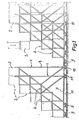
- the storage system is formed from a multiplicity of similar building blocks in the form of storage scaffolds 1, each of which accommodates a plurality of containers 2, and which can be assembled into groups by nesting through partial mutual engagement.
- each bearing frame 1 consists of a support frame 3 which is created from braced support profiles dimensioned according to the intended stress.
- the containers are stored in steps 4 arranged on the support frame 3 in the manner of stairs. These have the shape of the bases of the containers 2, which are designed such that they are in the top view (FIG. 3) of the storage frame or support frame as immediate appear next to one another, but are offset in height (FIG. 2) such that the vertical distance between the storage surfaces of two adjacent receptacles 4 is greater than the height of the containers 2 to be accommodated.
- the lower part 5 of the support frame 3 has essentially the shape of a flat U, the yoke 6 located on the front area of each bearing frame 1 out of the frame the lowest receptacle 4.1 and the legs 7 of which run diverging towards the rear from there. From the free ends of the legs 7 protrude supports 8 which support the frame of the uppermost receptacle 4.5 on its back.
- Said U-shaped lower part 5 of the support frame 3 is designed as a chassis and is supported for this purpose by running wheels in the form of track rollers 9 and 10. These are arranged and supported in the area of the approaches of the legs 7 on the yoke 6 and at the base of the supports 8, the divergence of the legs 7 resulting in a larger track width for the track rollers 10 located in the rear of the supports 8 than for the front Track rollers 9 attached in the area of the yoke 6.
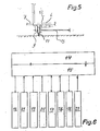
- the track rollers 9 and 10 run on pairs of rails 11 embedded in the storage space, which accordingly form tracks of different track widths laid symmetrically and parallel to one another. According to FIG.
- each bearing frame can also be equipped with several synchronously controlled geared motors.
- Such a warehouse organized with the described storage system is suitable for integration into a partially or fully automated container terminal due to the position of each individual container that can be precisely defined with sensors.
- the control and monitoring can take over a control circuit, the operating diagram of which is shown in FIG. 6.
- the central unit is a data memory 14 which is connected to a control computer 15 is in alternating connection. This operates the geared motors 12 of the undercarriages of the supporting frames 3 and a display system 16 for checking the occupancy and is connected to any external data memories 17 and means of transport computers 18.
- the control computer 15 is supplied with actual data by suitable sensors 19 and 20, which signal, for example, the completion of the exemption of a storage space for storage or retrieval, as well as by an identification and position detection system 21, which enables a position control and possible correction of the position.
- the completed individual processes can be acknowledged by a busy detection 22, which can optionally also be controlled externally.
- the functional sequence of the location system according to the invention when the warehouse is occupied is as follows: First, data about the container identifier and size are entered into the data memory 14. The entry can be made by hand or transferred from another computer. At the same time, further data such as weight, destination, hazard class of the goods to be transported, etc. can also be entered. The input can take the form of lists, the sequence of which is saved. The control computer 15 uses this to determine a vacant parking space, with optimization being sought so that the next vacant parking space is reached with as little movement of the storage structures as possible. Other criteria can also be taken into account, such as determination, hazard class, etc., if corresponding data has been entered.
- the location of the determined parking space and the container identifier are sent to the means of transport, such as a mobile crane, passed on, which can be done by direct transmission to the means of transport computer 18 or by activation of visual display means that the operator of the means of transport can read.
- the geared motors 12 of the bearing frames 1 to be moved for the exemption of the intended parking space are controlled.
- the control is optimized so that only the necessary movements are carried out in the correct order.
- the control also takes into account the drive power that is required to accelerate, drive and decelerate the bearing frames, with regard to the power limits of the power supply.
- the position of the vacant parking space is checked and, if necessary, corrected by suitable sensors of the position detection system 21, whereupon a corresponding feedback of the actual values takes place in the control computer.
- the selected parking space is now released for occupancy, which can be signaled by visual and / or acoustic display or by direct transmission to the means of transport computer 18, which causes the means of transport to place the particular container on the assigned space.
- the occupancy detection 22 reports the occupancy of the parking space to the computer 15, which checks whether the predetermined space has been occupied.
- the data about the container identifier and the parking space number and any further data are then stored in the data memory 14 and / or passed on to an external data memory. The system is thus free for a new entry or is able to address the next time to process.
- the container identifier of the corresponding container to be removed is entered, whereupon the control computer 15 determines the corresponding parking space. After the determination has been made, an order is sent to the geared motors 12 of the undercarriages of those storage racks which are to be moved to free the localized container so that the means of transport can be accessed. After checking the position and correcting it, the container is released and removed, which in turn is acknowledged by the occupancy detection. The unloading process ends when the container data is saved or stored in external memories.
Landscapes
- Engineering & Computer Science (AREA)
- Mechanical Engineering (AREA)
- Warehouses Or Storage Devices (AREA)
- Handcart (AREA)
- Supplying Of Containers To The Packaging Station (AREA)
Priority Applications (1)
| Application Number | Priority Date | Filing Date | Title |
|---|---|---|---|
| AT88106756T ATE68155T1 (de) | 1987-05-05 | 1988-04-27 | Lagersystem fuer container. |
Applications Claiming Priority (2)
| Application Number | Priority Date | Filing Date | Title |
|---|---|---|---|
| DE3714850 | 1987-05-05 | ||
| DE19873714850 DE3714850A1 (de) | 1987-05-05 | 1987-05-05 | Lagersystem fuer container |
Publications (3)
| Publication Number | Publication Date |
|---|---|
| EP0289931A2 true EP0289931A2 (fr) | 1988-11-09 |
| EP0289931A3 EP0289931A3 (en) | 1989-03-29 |
| EP0289931B1 EP0289931B1 (fr) | 1991-10-09 |
Family
ID=6326828
Family Applications (1)
| Application Number | Title | Priority Date | Filing Date |
|---|---|---|---|
| EP88106756A Expired - Lifetime EP0289931B1 (fr) | 1987-05-05 | 1988-04-27 | Système d'emmagasinage pour conteneurs |
Country Status (3)
| Country | Link |
|---|---|
| EP (1) | EP0289931B1 (fr) |
| AT (1) | ATE68155T1 (fr) |
| DE (2) | DE3714850A1 (fr) |
Families Citing this family (2)
| Publication number | Priority date | Publication date | Assignee | Title |
|---|---|---|---|---|
| DE19813291B4 (de) * | 1998-03-26 | 2006-04-13 | Günther, Roland, Prof. | Lagermittel, vorzugsweise für lange Lagereinheiten |
| DE202009014503U1 (de) * | 2009-10-27 | 2011-03-17 | Gepard Services Gmbh | Containerstapelgestell |
Family Cites Families (3)
| Publication number | Priority date | Publication date | Assignee | Title |
|---|---|---|---|---|
| US3078102A (en) * | 1960-11-14 | 1963-02-19 | Tote Cart Co | Cart support |
| FR1583614A (fr) * | 1966-09-05 | 1969-11-21 | ||
| GB1512396A (en) * | 1975-10-28 | 1978-06-01 | Bar Prod Ltd | Storage assemblies |
-
1987
- 1987-05-05 DE DE19873714850 patent/DE3714850A1/de not_active Withdrawn
-
1988
- 1988-04-27 AT AT88106756T patent/ATE68155T1/de not_active IP Right Cessation
- 1988-04-27 DE DE8888106756T patent/DE3865350D1/de not_active Expired - Lifetime
- 1988-04-27 EP EP88106756A patent/EP0289931B1/fr not_active Expired - Lifetime
Also Published As
| Publication number | Publication date |
|---|---|
| DE3714850A1 (de) | 1988-11-17 |
| ATE68155T1 (de) | 1991-10-15 |
| EP0289931A3 (en) | 1989-03-29 |
| DE3865350D1 (en) | 1991-11-14 |
| EP0289931B1 (fr) | 1991-10-09 |
Similar Documents
| Publication | Publication Date | Title |
|---|---|---|
| DE69204055T2 (de) | Automatisiertes lager und wagen zur einlagerung und entnahme von produkten in den speicherbereichen. | |
| EP2607292B1 (fr) | Système de transport des marchandises disposées sur les aides auxiliaires | |
| EP1140670B1 (fr) | Procede et systeme d'entreposage destines au transfert de charges | |
| EP2186754B1 (fr) | Installation de préparation et son procédé de fonctionnement avec un chariot de préparation | |
| DE2406378C3 (de) | Lagerhauseinrichtung | |
| DE3207860A1 (de) | Foerdereinrichtung fuer eine lagerhausanlage | |
| DE4133218A1 (de) | Abstellvorrichtung | |
| DE102016217632B4 (de) | Automatisches Parkhaus | |
| DE2114705A1 (de) | System zum Transport. Verladen und Lagern von Gegenstanden | |
| DE4338717A1 (de) | Automatische Park- und Lagereinrichtung für Kraftfahrzeuge | |
| EP4373766A1 (fr) | Système transtockeur, entrepôt à rayonnages en hauteur, procédé de mise en stock et de sortie du stock | |
| DE3023194A1 (de) | Regalbediengeraet | |
| EP0608689B1 (fr) | Dispositif de transport avec ou moins un engin pour l'extraction et le rangement d'une charge dans des cellules de rayonnage | |
| EP3214021A1 (fr) | Entrepôt et dispositif de préparation de commande pour un entrepôt | |
| DE20011842U1 (de) | Vorrichtung zum Kommissionieren von Stückgut | |
| EP1024096B1 (fr) | Système logistique pour l'expédition et la réception de produits, dispositifs, pour la lecture des données d'une ou plusieures mémoires de données et/ou l'écriture de données dans une mémoire de données , utilisés dans ce système logistique | |
| EP0289931B1 (fr) | Système d'emmagasinage pour conteneurs | |
| DE10033281A1 (de) | Arbeitsverfahren und Vorrichtung zum Kommissionieren von Stückgut | |
| EP0798238B1 (fr) | Système d'entreposage pour palettes pour objets longs | |
| EP4403484A1 (fr) | Palette de système multifonction | |
| CH702014A1 (de) | Regalanlage. | |
| DE4109294A1 (de) | Lasten-transfervorrichtung | |
| DE9210587U1 (de) | Anlage zum Ein- und Auslagern bzw. zur Speicherung von unterschiedlichen Gütern bzw. Lasten in einem eine Vielzahl von Stellplätzen aufweisenden Speichersilo | |
| EP4509439A1 (fr) | Station de transfert de charges dans des installations logistiques | |
| DE9409910U1 (de) | Lagervorrichtung für eine Last, insbesondere Personenkraftfahrzeuge, tragende Paletten |
Legal Events
| Date | Code | Title | Description |
|---|---|---|---|
| PUAI | Public reference made under article 153(3) epc to a published international application that has entered the european phase |
Free format text: ORIGINAL CODE: 0009012 |
|
| AK | Designated contracting states |
Kind code of ref document: A2 Designated state(s): AT BE CH DE ES FR GB GR IT LI LU NL SE |
|
| PUAL | Search report despatched |
Free format text: ORIGINAL CODE: 0009013 |
|
| AK | Designated contracting states |
Kind code of ref document: A3 Designated state(s): AT BE CH DE ES FR GB GR IT LI LU NL SE |
|
| 17P | Request for examination filed |
Effective date: 19890926 |
|
| 17Q | First examination report despatched |
Effective date: 19901213 |
|
| GRAA | (expected) grant |
Free format text: ORIGINAL CODE: 0009210 |
|
| AK | Designated contracting states |
Kind code of ref document: B1 Designated state(s): AT BE CH DE ES FR GB GR IT LI LU NL SE |
|
| PG25 | Lapsed in a contracting state [announced via postgrant information from national office to epo] |
Ref country code: IT Free format text: LAPSE BECAUSE OF FAILURE TO SUBMIT A TRANSLATION OF THE DESCRIPTION OR TO PAY THE FEE WITHIN THE PRE;WARNING: LAPSES OF ITALIAN PATENTS WITH EFFECTIVE DATE BEFORE 2007 MAY HAVE OCCURRED AT ANY TIME BEFORE 2007. THE CORRECT EFFECTIVE DATE MAY BE DIFFERENT FROM THE ONE RECORDED.SCRIBED TIME-LIMIT Effective date: 19911009 Ref country code: SE Effective date: 19911009 Ref country code: NL Effective date: 19911009 Ref country code: GR Free format text: LAPSE BECAUSE OF FAILURE TO SUBMIT A TRANSLATION OF THE DESCRIPTION OR TO PAY THE FEE WITHIN THE PRESCRIBED TIME-LIMIT Effective date: 19911009 Ref country code: ES Free format text: THE PATENT HAS BEEN ANNULLED BY A DECISION OF A NATIONAL AUTHORITY Effective date: 19911009 Ref country code: BE Effective date: 19911009 Ref country code: GB Effective date: 19911009 |
|
| REF | Corresponds to: |
Ref document number: 68155 Country of ref document: AT Date of ref document: 19911015 Kind code of ref document: T |
|
| REF | Corresponds to: |
Ref document number: 3865350 Country of ref document: DE Date of ref document: 19911114 |
|
| EN | Fr: translation not filed | ||
| PG25 | Lapsed in a contracting state [announced via postgrant information from national office to epo] |
Ref country code: FR Effective date: 19920228 |
|
| NLV1 | Nl: lapsed or annulled due to failure to fulfill the requirements of art. 29p and 29m of the patents act | ||
| GBV | Gb: ep patent (uk) treated as always having been void in accordance with gb section 77(7)/1977 [no translation filed] | ||
| PG25 | Lapsed in a contracting state [announced via postgrant information from national office to epo] |
Ref country code: AT Effective date: 19920427 |
|
| PG25 | Lapsed in a contracting state [announced via postgrant information from national office to epo] |
Ref country code: CH Effective date: 19920430 Ref country code: LI Effective date: 19920430 Ref country code: LU Free format text: LAPSE BECAUSE OF NON-PAYMENT OF DUE FEES Effective date: 19920430 |
|
| PLBE | No opposition filed within time limit |
Free format text: ORIGINAL CODE: 0009261 |
|
| STAA | Information on the status of an ep patent application or granted ep patent |
Free format text: STATUS: NO OPPOSITION FILED WITHIN TIME LIMIT |
|
| 26N | No opposition filed | ||
| REG | Reference to a national code |
Ref country code: CH Ref legal event code: PL |
|
| REG | Reference to a national code |
Ref country code: FR Ref legal event code: ST |
|
| PGFP | Annual fee paid to national office [announced via postgrant information from national office to epo] |
Ref country code: DE Payment date: 19990426 Year of fee payment: 12 |
|
| PG25 | Lapsed in a contracting state [announced via postgrant information from national office to epo] |
Ref country code: DE Free format text: LAPSE BECAUSE OF NON-PAYMENT OF DUE FEES Effective date: 20010201 |