EP0289369B1 - Procédé de fabrication d'un tuyau flexible comprenant des moyens de repérage et/ou de fixation - Google Patents
Procédé de fabrication d'un tuyau flexible comprenant des moyens de repérage et/ou de fixation Download PDFInfo
- Publication number
- EP0289369B1 EP0289369B1 EP88400423A EP88400423A EP0289369B1 EP 0289369 B1 EP0289369 B1 EP 0289369B1 EP 88400423 A EP88400423 A EP 88400423A EP 88400423 A EP88400423 A EP 88400423A EP 0289369 B1 EP0289369 B1 EP 0289369B1
- Authority
- EP
- European Patent Office
- Prior art keywords
- elastomeric composition
- layer
- flexible pipe
- wall
- hose
- Prior art date
- Legal status (The legal status is an assumption and is not a legal conclusion. Google has not performed a legal analysis and makes no representation as to the accuracy of the status listed.)
- Expired - Lifetime
Links
- 238000000034 method Methods 0.000 title claims abstract description 14
- 239000000203 mixture Substances 0.000 claims abstract description 72
- 238000004519 manufacturing process Methods 0.000 claims description 19
- 238000004073 vulcanization Methods 0.000 claims description 7
- 230000015572 biosynthetic process Effects 0.000 claims description 2
- 238000005304 joining Methods 0.000 claims description 2
- 239000012530 fluid Substances 0.000 abstract description 14
- 238000009472 formulation Methods 0.000 abstract description 12
- 239000007788 liquid Substances 0.000 abstract description 3
- 238000004378 air conditioning Methods 0.000 abstract description 2
- 239000007787 solid Substances 0.000 abstract 2
- 238000005452 bending Methods 0.000 abstract 1
- 239000011248 coating agent Substances 0.000 description 9
- 238000000576 coating method Methods 0.000 description 9
- 229920001971 elastomer Polymers 0.000 description 8
- 239000000806 elastomer Substances 0.000 description 7
- 239000000463 material Substances 0.000 description 7
- 230000001413 cellular effect Effects 0.000 description 6
- 230000003014 reinforcing effect Effects 0.000 description 6
- 239000004753 textile Substances 0.000 description 6
- 239000004744 fabric Substances 0.000 description 5
- KAKZBPTYRLMSJV-UHFFFAOYSA-N Butadiene Chemical compound C=CC=C KAKZBPTYRLMSJV-UHFFFAOYSA-N 0.000 description 4
- 230000000694 effects Effects 0.000 description 4
- 238000010438 heat treatment Methods 0.000 description 4
- 239000003795 chemical substances by application Substances 0.000 description 3
- 238000010276 construction Methods 0.000 description 3
- -1 ethylene, propylene Chemical group 0.000 description 3
- 229930195733 hydrocarbon Natural products 0.000 description 3
- 150000002430 hydrocarbons Chemical class 0.000 description 3
- 238000009434 installation Methods 0.000 description 3
- 230000002787 reinforcement Effects 0.000 description 3
- 230000035882 stress Effects 0.000 description 3
- NLHHRLWOUZZQLW-UHFFFAOYSA-N Acrylonitrile Chemical compound C=CC#N NLHHRLWOUZZQLW-UHFFFAOYSA-N 0.000 description 2
- 239000004604 Blowing Agent Substances 0.000 description 2
- 239000004709 Chlorinated polyethylene Substances 0.000 description 2
- 239000000470 constituent Substances 0.000 description 2
- 229920001577 copolymer Polymers 0.000 description 2
- 150000001993 dienes Chemical class 0.000 description 2
- USIUVYZYUHIAEV-UHFFFAOYSA-N diphenyl ether Chemical compound C=1C=CC=CC=1OC1=CC=CC=C1 USIUVYZYUHIAEV-UHFFFAOYSA-N 0.000 description 2
- 238000001125 extrusion Methods 0.000 description 2
- 235000013305 food Nutrition 0.000 description 2
- 238000000465 moulding Methods 0.000 description 2
- 239000003921 oil Substances 0.000 description 2
- 239000011253 protective coating Substances 0.000 description 2
- 238000010057 rubber processing Methods 0.000 description 2
- 239000000126 substance Substances 0.000 description 2
- 229920001897 terpolymer Polymers 0.000 description 2
- 238000012546 transfer Methods 0.000 description 2
- XLYOFNOQVPJJNP-UHFFFAOYSA-N water Substances O XLYOFNOQVPJJNP-UHFFFAOYSA-N 0.000 description 2
- OZAIFHULBGXAKX-UHFFFAOYSA-N 2-(2-cyanopropan-2-yldiazenyl)-2-methylpropanenitrile Chemical compound N#CC(C)(C)N=NC(C)(C)C#N OZAIFHULBGXAKX-UHFFFAOYSA-N 0.000 description 1
- 208000012260 Accidental injury Diseases 0.000 description 1
- ATRRKUHOCOJYRX-UHFFFAOYSA-N Ammonium bicarbonate Chemical compound [NH4+].OC([O-])=O ATRRKUHOCOJYRX-UHFFFAOYSA-N 0.000 description 1
- 239000004156 Azodicarbonamide Substances 0.000 description 1
- MWRWFPQBGSZWNV-UHFFFAOYSA-N Dinitrosopentamethylenetetramine Chemical compound C1N2CN(N=O)CN1CN(N=O)C2 MWRWFPQBGSZWNV-UHFFFAOYSA-N 0.000 description 1
- 101100536354 Drosophila melanogaster tant gene Proteins 0.000 description 1
- 244000043261 Hevea brasiliensis Species 0.000 description 1
- RRHGJUQNOFWUDK-UHFFFAOYSA-N Isoprene Chemical compound CC(=C)C=C RRHGJUQNOFWUDK-UHFFFAOYSA-N 0.000 description 1
- 229920000914 Metallic fiber Polymers 0.000 description 1
- 240000007817 Olea europaea Species 0.000 description 1
- 230000032683 aging Effects 0.000 description 1
- 235000012501 ammonium carbonate Nutrition 0.000 description 1
- 239000001099 ammonium carbonate Substances 0.000 description 1
- XOZUGNYVDXMRKW-AATRIKPKSA-N azodicarbonamide Chemical compound NC(=O)\N=N\C(N)=O XOZUGNYVDXMRKW-AATRIKPKSA-N 0.000 description 1
- 235000019399 azodicarbonamide Nutrition 0.000 description 1
- 238000009954 braiding Methods 0.000 description 1
- 238000004132 cross linking Methods 0.000 description 1
- 238000005520 cutting process Methods 0.000 description 1
- 238000011161 development Methods 0.000 description 1
- 230000018109 developmental process Effects 0.000 description 1
- 238000009826 distribution Methods 0.000 description 1
- 229940082150 encore Drugs 0.000 description 1
- 208000014674 injury Diseases 0.000 description 1
- 229910052500 inorganic mineral Inorganic materials 0.000 description 1
- 238000009940 knitting Methods 0.000 description 1
- 239000002184 metal Substances 0.000 description 1
- 239000008267 milk Substances 0.000 description 1
- 210000004080 milk Anatomy 0.000 description 1
- 235000013336 milk Nutrition 0.000 description 1
- 239000011707 mineral Substances 0.000 description 1
- 238000012986 modification Methods 0.000 description 1
- 230000004048 modification Effects 0.000 description 1
- 239000000178 monomer Substances 0.000 description 1
- 229920003052 natural elastomer Polymers 0.000 description 1
- 229920001194 natural rubber Polymers 0.000 description 1
- 150000002894 organic compounds Chemical class 0.000 description 1
- 230000001590 oxidative effect Effects 0.000 description 1
- 229920001084 poly(chloroprene) Polymers 0.000 description 1
- 229920001195 polyisoprene Polymers 0.000 description 1
- 238000002360 preparation method Methods 0.000 description 1
- 239000012779 reinforcing material Substances 0.000 description 1
- 238000007789 sealing Methods 0.000 description 1
- 239000000725 suspension Substances 0.000 description 1
- 230000009466 transformation Effects 0.000 description 1
Images


Classifications
-
- B—PERFORMING OPERATIONS; TRANSPORTING
- B29—WORKING OF PLASTICS; WORKING OF SUBSTANCES IN A PLASTIC STATE IN GENERAL
- B29D—PRODUCING PARTICULAR ARTICLES FROM PLASTICS OR FROM SUBSTANCES IN A PLASTIC STATE
- B29D23/00—Producing tubular articles
- B29D23/001—Pipes; Pipe joints
- B29D23/003—Pipe joints, e.g. straight joints
-
- B—PERFORMING OPERATIONS; TRANSPORTING
- B29—WORKING OF PLASTICS; WORKING OF SUBSTANCES IN A PLASTIC STATE IN GENERAL
- B29D—PRODUCING PARTICULAR ARTICLES FROM PLASTICS OR FROM SUBSTANCES IN A PLASTIC STATE
- B29D23/00—Producing tubular articles
- B29D23/001—Pipes; Pipe joints
- B29D23/003—Pipe joints, e.g. straight joints
- B29D23/006—Elbows
-
- B—PERFORMING OPERATIONS; TRANSPORTING
- B29—WORKING OF PLASTICS; WORKING OF SUBSTANCES IN A PLASTIC STATE IN GENERAL
- B29C—SHAPING OR JOINING OF PLASTICS; SHAPING OF MATERIAL IN A PLASTIC STATE, NOT OTHERWISE PROVIDED FOR; AFTER-TREATMENT OF THE SHAPED PRODUCTS, e.g. REPAIRING
- B29C44/00—Shaping by internal pressure generated in the material, e.g. swelling or foaming ; Producing porous or cellular expanded plastics articles
- B29C44/34—Auxiliary operations
- B29C44/36—Feeding the material to be shaped
- B29C44/46—Feeding the material to be shaped into an open space or onto moving surfaces, i.e. to make articles of indefinite length
- B29C44/50—Feeding the material to be shaped into an open space or onto moving surfaces, i.e. to make articles of indefinite length using pressure difference, e.g. by extrusion or by spraying
- B29C44/507—Feeding the material to be shaped into an open space or onto moving surfaces, i.e. to make articles of indefinite length using pressure difference, e.g. by extrusion or by spraying extruding the compound through an annular die
-
- B—PERFORMING OPERATIONS; TRANSPORTING
- B29—WORKING OF PLASTICS; WORKING OF SUBSTANCES IN A PLASTIC STATE IN GENERAL
- B29C—SHAPING OR JOINING OF PLASTICS; SHAPING OF MATERIAL IN A PLASTIC STATE, NOT OTHERWISE PROVIDED FOR; AFTER-TREATMENT OF THE SHAPED PRODUCTS, e.g. REPAIRING
- B29C53/00—Shaping by bending, folding, twisting, straightening or flattening; Apparatus therefor
- B29C53/02—Bending or folding
- B29C53/08—Bending or folding of tubes or other profiled members
-
- F—MECHANICAL ENGINEERING; LIGHTING; HEATING; WEAPONS; BLASTING
- F16—ENGINEERING ELEMENTS AND UNITS; GENERAL MEASURES FOR PRODUCING AND MAINTAINING EFFECTIVE FUNCTIONING OF MACHINES OR INSTALLATIONS; THERMAL INSULATION IN GENERAL
- F16L—PIPES; JOINTS OR FITTINGS FOR PIPES; SUPPORTS FOR PIPES, CABLES OR PROTECTIVE TUBING; MEANS FOR THERMAL INSULATION IN GENERAL
- F16L11/00—Hoses, i.e. flexible pipes
- F16L11/04—Hoses, i.e. flexible pipes made of rubber or flexible plastics
-
- F—MECHANICAL ENGINEERING; LIGHTING; HEATING; WEAPONS; BLASTING
- F16—ENGINEERING ELEMENTS AND UNITS; GENERAL MEASURES FOR PRODUCING AND MAINTAINING EFFECTIVE FUNCTIONING OF MACHINES OR INSTALLATIONS; THERMAL INSULATION IN GENERAL
- F16L—PIPES; JOINTS OR FITTINGS FOR PIPES; SUPPORTS FOR PIPES, CABLES OR PROTECTIVE TUBING; MEANS FOR THERMAL INSULATION IN GENERAL
- F16L11/00—Hoses, i.e. flexible pipes
- F16L11/04—Hoses, i.e. flexible pipes made of rubber or flexible plastics
- F16L11/08—Hoses, i.e. flexible pipes made of rubber or flexible plastics with reinforcements embedded in the wall
-
- F—MECHANICAL ENGINEERING; LIGHTING; HEATING; WEAPONS; BLASTING
- F16—ENGINEERING ELEMENTS AND UNITS; GENERAL MEASURES FOR PRODUCING AND MAINTAINING EFFECTIVE FUNCTIONING OF MACHINES OR INSTALLATIONS; THERMAL INSULATION IN GENERAL
- F16L—PIPES; JOINTS OR FITTINGS FOR PIPES; SUPPORTS FOR PIPES, CABLES OR PROTECTIVE TUBING; MEANS FOR THERMAL INSULATION IN GENERAL
- F16L11/00—Hoses, i.e. flexible pipes
- F16L11/04—Hoses, i.e. flexible pipes made of rubber or flexible plastics
- F16L11/11—Hoses, i.e. flexible pipes made of rubber or flexible plastics with corrugated wall
- F16L11/118—Hoses, i.e. flexible pipes made of rubber or flexible plastics with corrugated wall having arrangements for particular purposes, e.g. electrically conducting
-
- F—MECHANICAL ENGINEERING; LIGHTING; HEATING; WEAPONS; BLASTING
- F16—ENGINEERING ELEMENTS AND UNITS; GENERAL MEASURES FOR PRODUCING AND MAINTAINING EFFECTIVE FUNCTIONING OF MACHINES OR INSTALLATIONS; THERMAL INSULATION IN GENERAL
- F16L—PIPES; JOINTS OR FITTINGS FOR PIPES; SUPPORTS FOR PIPES, CABLES OR PROTECTIVE TUBING; MEANS FOR THERMAL INSULATION IN GENERAL
- F16L11/00—Hoses, i.e. flexible pipes
- F16L11/04—Hoses, i.e. flexible pipes made of rubber or flexible plastics
- F16L11/12—Hoses, i.e. flexible pipes made of rubber or flexible plastics with arrangements for particular purposes, e.g. specially profiled, with protecting layer, heated, electrically conducting
- F16L11/122—Hoses provided with integrated fixing means, e.g. hooks
-
- F—MECHANICAL ENGINEERING; LIGHTING; HEATING; WEAPONS; BLASTING
- F16—ENGINEERING ELEMENTS AND UNITS; GENERAL MEASURES FOR PRODUCING AND MAINTAINING EFFECTIVE FUNCTIONING OF MACHINES OR INSTALLATIONS; THERMAL INSULATION IN GENERAL
- F16L—PIPES; JOINTS OR FITTINGS FOR PIPES; SUPPORTS FOR PIPES, CABLES OR PROTECTIVE TUBING; MEANS FOR THERMAL INSULATION IN GENERAL
- F16L33/00—Arrangements for connecting hoses to rigid members; Rigid hose-connectors, i.e. single members engaging both hoses
- F16L33/02—Hose-clips
-
- F—MECHANICAL ENGINEERING; LIGHTING; HEATING; WEAPONS; BLASTING
- F16—ENGINEERING ELEMENTS AND UNITS; GENERAL MEASURES FOR PRODUCING AND MAINTAINING EFFECTIVE FUNCTIONING OF MACHINES OR INSTALLATIONS; THERMAL INSULATION IN GENERAL
- F16L—PIPES; JOINTS OR FITTINGS FOR PIPES; SUPPORTS FOR PIPES, CABLES OR PROTECTIVE TUBING; MEANS FOR THERMAL INSULATION IN GENERAL
- F16L35/00—Special arrangements used in connection with end fittings of hoses, e.g. safety or protecting devices
-
- F—MECHANICAL ENGINEERING; LIGHTING; HEATING; WEAPONS; BLASTING
- F16—ENGINEERING ELEMENTS AND UNITS; GENERAL MEASURES FOR PRODUCING AND MAINTAINING EFFECTIVE FUNCTIONING OF MACHINES OR INSTALLATIONS; THERMAL INSULATION IN GENERAL
- F16L—PIPES; JOINTS OR FITTINGS FOR PIPES; SUPPORTS FOR PIPES, CABLES OR PROTECTIVE TUBING; MEANS FOR THERMAL INSULATION IN GENERAL
- F16L59/00—Thermal insulation in general
- F16L59/14—Arrangements for the insulation of pipes or pipe systems
- F16L59/143—Pre-insulated pipes
-
- F—MECHANICAL ENGINEERING; LIGHTING; HEATING; WEAPONS; BLASTING
- F16—ENGINEERING ELEMENTS AND UNITS; GENERAL MEASURES FOR PRODUCING AND MAINTAINING EFFECTIVE FUNCTIONING OF MACHINES OR INSTALLATIONS; THERMAL INSULATION IN GENERAL
- F16L—PIPES; JOINTS OR FITTINGS FOR PIPES; SUPPORTS FOR PIPES, CABLES OR PROTECTIVE TUBING; MEANS FOR THERMAL INSULATION IN GENERAL
- F16L59/00—Thermal insulation in general
- F16L59/14—Arrangements for the insulation of pipes or pipe systems
- F16L59/153—Arrangements for the insulation of pipes or pipe systems for flexible pipes
-
- Y—GENERAL TAGGING OF NEW TECHNOLOGICAL DEVELOPMENTS; GENERAL TAGGING OF CROSS-SECTIONAL TECHNOLOGIES SPANNING OVER SEVERAL SECTIONS OF THE IPC; TECHNICAL SUBJECTS COVERED BY FORMER USPC CROSS-REFERENCE ART COLLECTIONS [XRACs] AND DIGESTS
- Y10—TECHNICAL SUBJECTS COVERED BY FORMER USPC
- Y10T—TECHNICAL SUBJECTS COVERED BY FORMER US CLASSIFICATION
- Y10T29/00—Metal working
- Y10T29/49—Method of mechanical manufacture
- Y10T29/49428—Gas and water specific plumbing component making
- Y10T29/49435—Flexible conduit or fitting therefor
-
- Y—GENERAL TAGGING OF NEW TECHNOLOGICAL DEVELOPMENTS; GENERAL TAGGING OF CROSS-SECTIONAL TECHNOLOGIES SPANNING OVER SEVERAL SECTIONS OF THE IPC; TECHNICAL SUBJECTS COVERED BY FORMER USPC CROSS-REFERENCE ART COLLECTIONS [XRACs] AND DIGESTS
- Y10—TECHNICAL SUBJECTS COVERED BY FORMER USPC
- Y10T—TECHNICAL SUBJECTS COVERED BY FORMER US CLASSIFICATION
- Y10T29/00—Metal working
- Y10T29/49—Method of mechanical manufacture
- Y10T29/49826—Assembling or joining
- Y10T29/49863—Assembling or joining with prestressing of part
- Y10T29/49865—Assembling or joining with prestressing of part by temperature differential [e.g., shrink fit]
-
- Y—GENERAL TAGGING OF NEW TECHNOLOGICAL DEVELOPMENTS; GENERAL TAGGING OF CROSS-SECTIONAL TECHNOLOGIES SPANNING OVER SEVERAL SECTIONS OF THE IPC; TECHNICAL SUBJECTS COVERED BY FORMER USPC CROSS-REFERENCE ART COLLECTIONS [XRACs] AND DIGESTS
- Y10—TECHNICAL SUBJECTS COVERED BY FORMER USPC
- Y10T—TECHNICAL SUBJECTS COVERED BY FORMER US CLASSIFICATION
- Y10T29/00—Metal working
- Y10T29/49—Method of mechanical manufacture
- Y10T29/49826—Assembling or joining
- Y10T29/49908—Joining by deforming
- Y10T29/49909—Securing cup or tube between axially extending concentric annuli
- Y10T29/49911—Securing cup or tube between axially extending concentric annuli by expanding inner annulus
-
- Y—GENERAL TAGGING OF NEW TECHNOLOGICAL DEVELOPMENTS; GENERAL TAGGING OF CROSS-SECTIONAL TECHNOLOGIES SPANNING OVER SEVERAL SECTIONS OF THE IPC; TECHNICAL SUBJECTS COVERED BY FORMER USPC CROSS-REFERENCE ART COLLECTIONS [XRACs] AND DIGESTS
- Y10—TECHNICAL SUBJECTS COVERED BY FORMER USPC
- Y10T—TECHNICAL SUBJECTS COVERED BY FORMER US CLASSIFICATION
- Y10T29/00—Metal working
- Y10T29/49—Method of mechanical manufacture
- Y10T29/49826—Assembling or joining
- Y10T29/49908—Joining by deforming
- Y10T29/49938—Radially expanding part in cavity, aperture, or hollow body
- Y10T29/4994—Radially expanding internal tube
Definitions
- the invention relates to the field of transfer or circulation of fluids in industrial or automotive applications.
- Document FR 2,520,664 of the applicant describes a method of molding the ends of flexible rubber hoses which also makes it possible to produce grooves or ribs.
- the object of the invention is therefore the development of a flexible pipe, of simple manufacture - therefore inexpensive and not requiring the use of expensive tools - comprising in its wall a cellular material, said flexible pipe being provided with means for locating, mounting or identifying integrated in zones of said wall.
- the process for producing said flexible pipe which is the subject of the invention, is characterized in that the component in cellular elastomeric composition of the wall of said pipe is prevented from expanding, in thickness, during manufacture, totally or partially, in at least one of said zones corresponding to the creation of ribs or grooves for the installation of hose clamps on the end piece, to the creation of identification marks or supports or to the creation of shoulders.
- the flexible pipe also comprises, more often than not, interposed between the internal tube and the cellularized coating, at least one reinforcing element, made up of fabrics, threads or textile or metallic cables, and, possibly a thin layer made of compact elastomeric composition, inserted between the reinforcing material and the cellularizable elastomeric composition.
- the flexible hose Under certain conditions of use in harsh environments, particularly abrasive or corrosive, it is also possible to provide the flexible hose with a protective coating at the periphery of the cellularized zone which then partially constitutes the wall, the protective coating possibly being or no, as required, separated from the cellularized wall by interposition of an element - most generally textile - stress distributor and designated under the terms of "breaker” or "external liner".
- the method of manufacturing said flexible hose consists in that the cellularizable elastomeric composition - which constitutes a thickness component and extends over all or part of the length of the flexible hose - is in compact form at the time of making said hose.
- Said method of manufacturing the flexible pipe is therefore characterized in that this expansion is locally limited by suitable means such as shells placed in the areas where the expansion must be controlled.
- FIG. 1 describes, by way of nonlimiting examples, some possibilities of constituting the flexible pipe, to which the manufacturing process, object of the invention applies.
- View 1a illustrates, in cross section, the simplest constitution in which the flexible pipe (1) has only two elements, that is, from the inside to the outside, an internal tube (2), made of elastomeric composition compact of thickness (e) and a layer (3), in cellularized elastomeric composition of thickness (c).
- the ratio of the thickness (e) of the layer of compact elastomeric composition which constitutes the internal tube (2) to the thickness (c) of the layer of cellularized elastomeric composition is between 0.09 and 1 .
- the compact elastomeric composition of the internal tube (2) will receive a suitable formulation, in order to allow said internal tube (2) to resist the transported fluid.
- the basic elastomer of the compact elastomeric composition constituting the internal tube (2) will be a terpolymer of ethylene, propylene and a third diene monomer (EPDM) if the internal tube must resist heat or oxidizing fluids.
- EPDM will be avoided, as the basic elastomer of the compact elastomeric composition of the internal tube (2) for the transport of oils or hydrocarbons.
- a particular formulation which can also be based on EPDM, will be adopted for the transport of food fluids, such as water, milk or wine, or fluids brought into contact. with food.
- the basic elastomer of the compact elastomeric composition of the inner tube (2) will preferably be a copolymer of butadiene and acrylonitrile (NBR) or chlorinated polyethylene (CM) for the transport of liquid or gaseous hydrocarbons and fatty products .
- NBR butadiene and acrylonitrile
- CM chlorinated polyethylene
- NBR will be avoided as the basic elastomer of the compact elastomeric composition of the internal tube (2) if the flexible pipe is intended for the transport of hot water.
- Polychloroprene will preferably be adopted as the basic elastomer of the compact elastomeric composition of the internal tube (2) for the transport of oils and hydrocarbons, such as NBR, but also for the transport of a large number of chemical fluids under attack. which it offers good resistance.
- the elastomeric cellularisable composition of the layer (3) will receive a suitable formulation, in order to allow the flexible hose (1) to resist the environment in which it will be used.
- Said cellularizable elastomeric composition comprises a basic elastomer such as, by way of nonlimiting examples, natural rubber, SBR, a terpolymer of ethylene, propylene and a diene termonomer (EPDM), a copolymer of butadiene and acrylonitrile (NBR) or chlorinated polyethylene (CM).
- a basic elastomer such as, by way of nonlimiting examples, natural rubber, SBR, a terpolymer of ethylene, propylene and a diene termonomer (EPDM), a copolymer of butadiene and acrylonitrile (NBR) or chlorinated polyethylene (CM).
- the vulcanization and aging protection systems as well as the loads are adapted to the conditions of use.
- the elastomeric cellularisable composition contains, in addition, a pore-forming agent which will cause, under the effect of a heat treatment, the formation of cells and can, by way of nonlimiting examples, be chosen from organic compounds such as azodicarbonamide, azodiisobutyronitrile, pp′oxy bis benzene sulfonylhydrazide or dinitrosopentamethylene tetramine. It is also possible to use a mineral blowing agent such as an ammonium carbonate.
- the nature and the proportion of pore-forming agent introduced into the elastomer are a function of the density and the size of the cells sought.
- the cellularizable elastomeric composition of the layer (3) is in compact form when it is laid on all or part of the periphery of the layer in compact elastomeric composition constituting the internal tube (2), during the preparation of the flexible pipe. (1), the cellularization intervening only during the vulcanization heat treatment which must take place at a suitable temperature to cause the reaction of the blowing agent.
- View 1b illustrates another constitution of the flexible pipe (1), in which a reinforcing layer (4), made of fabric, textile or metallic threads or cables was inserted between the internal tube (2) and the layer of cellularized elastomeric composition (3), which makes it possible to "give body" to the flexible pipe (1).
- a reinforcing layer (4) made of fabric, textile or metallic threads or cables was inserted between the internal tube (2) and the layer of cellularized elastomeric composition (3), which makes it possible to "give body" to the flexible pipe (1).
- View 1c represents a variant construction of the flexible pipe (1) in which a thin layer (5), in compact elastomeric composition, is added between the reinforcing element (4), placed outside the internal tube in elastomeric composition, also compact ( 2), and the layer in cellularized elastomeric composition (3), in order to create a gradient of modules from the high modulus of the reinforcement element (4) to the apparent, low modulus of the layer in cellularized elastomeric composition ( 3), which has the effect of ensuring a better distribution of the stresses and of increasing the adhesion between the constituent elements of the flexible pipe.
- the cellularized elastomeric composition (3) comprises, at its external periphery, an integrated skin, coming directly from manufacture, having a substantially smooth appearance and constituting the coating of the flexible pipe (1).
- the flexible pipe (1) can, moreover, receive, above the constitutions previously illustrated, a coating (6) in compact elastomeric composition, of formulation adapted to the constraints of use, which leads to the constitutions of views 1d and 1e, for example, corresponding respectively to views 1a and 1b.
- the view 1f shows diagrammatically the construction of a flexible pipe (1) in which two reinforcing elements made up of fabric, threads or textile or metallic cables (4a) and (4b) are interposed between the internal tube (2) and the layer in cellularized elastomeric composition (3) on which a stress-distributing element is placed, generally called “breaker” (7) and made of fabric or metallic or textile cables, itself covered with an external coating (6) intended to protect the flexible pipe (1) in the event of use in hostile environment.
- breaker made of fabric or metallic or textile cables
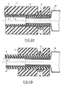
- FIG. 2 shows two embodiments of flexible pipes with a clamp integrated in the wall.
- View 2a shows, in section, how the flexible pipe (1), consisting of the inner tube (2) in compact elastomeric composition, the reinforcing element (4), the thin layer in compact elastomeric composition (5) and of the layer (3) of cellularized elastomeric composition can be fitted, during manufacture, with a clamp (10) - generally metallic - possibly provided with a screw (11) as shown, or with any other fixing means, allowing the tight mounting of said flexible pipe (1) on a rigid end piece (12) which provides connection to a motor or machine member.
- a clamp 10 - generally metallic - possibly provided with a screw (11) as shown, or with any other fixing means, allowing the tight mounting of said flexible pipe (1) on a rigid end piece (12) which provides connection to a motor or machine member.
- the clamping to be effective, it is necessary that it takes place on a non-cellularized material.
- the technique, object of the invention, used for equipping the flexible pipe (1) by the clamping collar (10) consists in preventing cellularization of the elastomeric composition of the layer (3) in the region of the collar, by the use of shells or of the necklace itself.
- the flexible pipes thus produced therefore include collars inserted into suitable housings and which, consequently, can no longer be lost, during the installation of the flexible pipe on the installation, as this frequently occurs by sliding of said collar along the end in the case of conventional pipes.
- This technique also makes it possible to ensure correct positioning of said collar on the end piece, to prevent tightening taking place on the olive, which would cause a lack of tightness.
- Figure 3 shows two variants of the flexible hose, using the same principle of construction.
- the end (A) of the flexible pipe (1) has a shoulder (13), separated from the rest of the body of the pipe by a groove (14).
- the variant shown has a single groove (14), but it is obvious to those skilled in the art that several grooves, of similar or different shapes - can be produced by the same process, to constitute identification marks or mounting, for example.
- the principle of embodiment applied uses, partially, the same principle as that described for the realization of the variants of FIG. 2 since it makes it possible to control the expansion of the cellularizable elastomeric composition constituting the layer (3) placed above the internal tube.
- (2) in a compact elastomeric composition by molding the end (A) in a shell whose imprint has the desired shape.
- the groove (14) is formed and by limiting expansion, the shoulder (13) is formed.
- View 3b illustrates the application of the same principle to the production of multiple grooves (14), spaced along the body of the flexible pipe (1), to have, for example, from place to place, suspension devices to allow hooking in multiple points, for crossing a workshop, a building site or a space of great length, leaving the flexible pipe a certain flexibility, without causing the wall to snag at the hooking points.
- Such a device would be very appreciable, for example, for the fluid lines of any material called upon to move, such as overhead traveling cranes.
- a manufacturing method according to the invention of the flexible hose consists of a production in great length, according to the extrusion techniques usually used in the rubber processing industry.
- the compact elastomeric composition of formulation adapted to the fluid to be conveyed, which constitutes the internal tube, then - optionally - to deposit continuously, for example by covering, by braiding or by knitting, the material (or them) ( x) reinforcement and then placing, over all or part of the length, an elastomeric composition then compact but containing pore-forming agents, allowing it to cellularize under the effect of heat.
- the corresponding compact elastomeric composition is also deposited, for example by extrusion, either directly above the composition layer elastomeric cellularisable either after interposition of a stress-distributing element, most often made of fabric, threads or textile or metallic cables.
- the assembly is then vulcanized by traditional means, either in great length, or in shape, after cutting to the desired length and mounting on a mandrel of suitable shape.
- the heat treatment simultaneously ensures the cellularization of the cellularizable elastomeric layer, the crosslinking of all the elastomeric compositions and the joining of the various constituent elements.
- the flexible hose with integrated hose clamp on a flexible hose comprising, over all or part of its length, a layer of cellularizable elastomeric composition
- the tightening collar itself possibly isolated from the cellularisable layer by a ribbon, will be used for tightening on the mandrel and may therefore remain in place after vulcanization.
- the flexible hose produced according to the process which is the subject of the invention, is used in all industrial fields requiring the transfer of a fluid - liquid, gaseous, or even powdery - or on the various fluid and / or air conditioning circuits d 'a motor vehicle, and further provides ease of location, identification, and / or assembly.
Landscapes
- Engineering & Computer Science (AREA)
- General Engineering & Computer Science (AREA)
- Mechanical Engineering (AREA)
- Rigid Pipes And Flexible Pipes (AREA)
- Laminated Bodies (AREA)
- Molding Of Porous Articles (AREA)
- Lining Or Joining Of Plastics Or The Like (AREA)
- Extrusion Moulding Of Plastics Or The Like (AREA)
- Bending Of Plates, Rods, And Pipes (AREA)
- Shaping Of Tube Ends By Bending Or Straightening (AREA)
Description
- L'invention concerne le domaine du transfert ou de la circulation des fluides dans les applications industrielles ou automobiles.
- Elle consiste en la réalisation sur des tuyaux flexibles, comportant une paroi au moins partiellement cellularisée, de nervures, de gorges, de repères d'identification ou d'épaulements.
- Le document FR 2.520.664 de la demanderesse décrit un procédé de moulage des extrémités de tuyaux souples en caoutchouc qui permet, en outre, de réaliser des gorges ou des nervures.
- L'inconvénient d'un tel procédé est de mettre en oeuvre un serrage radial des extrémités qui, en raison des contraintes exercées serait inapplicable à un tuyau flexible comportant une paroi en matériau cellularisable. En outre, la création des gorges ou nervures n'est réalisable que dans les zones d'extrémité.
- Les réalisations de l'art antérieur ne prévoient pas la possibilité de créer, en quelque emplacement que ce soit, de manière simple, dans l'épaisseur cellulaire de paroi de tuyaux flexibles des gorges, des nervures, des repères ou des épaulements.
- L'objet de l'invention est donc la mise au point d'un tuyau flexible, d'une fabrication simple ― donc peu coûteuse et ne nécessitant pas l'utilisation d'un outillage onéreux ― comportant dans sa paroi un matériau cellularisé, ledit tuyau flexible étant muni de moyens de repérage, de montage ou d'identification intégrés dans des zones de ladite paroi.
- Le procédé de réalisation dudit tuyau flexible, objet de l'invention, est caractérisé en ce que le constituant en composition élastomérique cellularisable de la paroi dudit tuyau est empéché de s'expanser, en épaisseur, au cours de la fabrication, totalement ou partiellement, dans au moins une desdites zones correspondant à la création de nervures ou de gorges pour la pose de colliers de serrage sur embout, à la création de repères d'identification ou de supports ou encore à la création d'épaulements.
- Dans une variante, c'est par la présence du collier de serrage lui-même qu'est empéchée, localement, l'expansion en épaisseur, totale ou partielle, de la composition élastomérique cellularisable, composant de la paroi dudit tuyau.
- Le procédé de réalisation, objet de l'invention, concerne un tuyau flexible, constitué, au moins, des éléments suivants, de l'intérieur vers l'extérieur:
- ― un tube interne, réalisé en composition élastomérique compacte, de formulation adaptée au fluide à véhiculer,
- ― et un revêtement externe cellulaire, réalisé dans une composition élastomérique cellularisable, de formulation adaptée aux conditions d'utilisation et capable de former une peau extérieure quasi compacte, d'aspect sensiblement lisse, ledit revêtement cellularisé pouvant revêtir tout ou partie de la longueur du tuyau.
- Le tuyau flexible comprend, en outre, le plus souvent, interposé entre le tube interne et le revêtement cellularisé, au moins un élément de renfort, constitué de tissus, de fils ou de cablés textiles ou métalliques, et, éventuellement une fine couche réalisée en composition élastomérique compacte, insérée entre le matériau de renforcement et la composition élastomérique cellularisable.
- Dans certaines conditions d'utilisation en environnement sévère, particulièrement abrasif ou corrosif, il est également possible de munir le tuyau flexible d'un revêtement protecteur à la périphérie de la zone cellularisée qui en constitue alors partiellement la paroi, le revêtement protecteur pouvant être ou non, selon les besoins, séparé de la paroi cellularisée par interposition d'un élément ― le plus généralement textile ― répartiteur de contraintes et désigné sous les termes de "breaker" ou de "liner externe".
- Le procédé de fabrication dudit tuyau flexible consiste en ce que la composition élastomérique cellularisable ― qui constitue un composant de l'épaisseur et s'étend sur tout ou partie de la longueur du tuyau flexible ― se présente sous forme compacte au moment de la confection dudit tuyau flexible et ne s'expanse, pour former une couche de matériau cellulaire, qu'au moment du traitement thermique destiné à provoquer la vulcanisation des composants élastomériques.
- Ledit procédé de fabrication du tuyau flexible est donc caractérisé en ce que cette expansion est localement limitée par des moyens appropriés tels que des coquilles placées dans les zones où l'expansion doit être contrôlée.
- Les caractéristiques et variantes de l'invention seront mieux comprises à la lecture de la description accompagnant les dessins, dans lesquels:
- ― la figure 1 décrit quelques possibilités de constitution du tuyau flexible;
- ― la figure 2 présente deux variantes du tuyau flexible à collier de serrage intégré à la paroi;
- ― la figure 3 montre deux variantes du tuyau flexible utilisant, également, l'expansion limitée de la composition élastomérique cellularisable;
- La figure 1 décrit, à titre d'exemples non limitatifs, quelques possibilités de constitution du tuyau flexible, auquel s'applique le procédé de fabrication, objet de l'invention.
- La vue 1a illustre, en coupe transversale, la constitution la plus simple dans laquelle le tuyau flexible (1) ne comporte que deux éléments, soit, de l'intérieur vers l'extérieur, un tube interne (2), réalisé en composition élastomérique compacte d'épaisseur (e) et une couche (3), en composition élastomérique cellularisée d'épaisseur (c).
- Dans les configurations les plus usuelles, l'épaisseur (e) de la couche en composition élastomérique compacte constituant le tube interne (2) est faible devant l'épaisseur totale (E = Re - Ri), Re étant le rayon extérieur de la section et Ri le rayon intérieur de la section du tuyau flexible.
- Le plus généralement, le rapport de l'épaisseur (e) de la couche en composition élastomérique compacte qui constitue le tube interne (2) à l'épaisseur (c) de la couche en composition élastomérique cellularisée est comprise entre 0,09 et 1.
- Il est cependant des cas où le rapport de l'épaisseur (e) de la couche en composition élastomérique compacte (2) à l'épaisseur totale (E) de la paroi peut atteindre ― voire dépasser ― 0,80.
- La composition élastomérique compacte du tube interne (2) recevra une formulation adaptée, afin de permettre audit tube interne (2) de résister au fluide véhiculé.
- C'est ainsi, par exemple, que l'élastomère de base de la composition élastomérique compacte constituant le tube interne (2) sera un terpolymère d'éthylène, de propylène et d'un troisième monomère diénique (EPDM) si le tube interne doit résister à la chaleur ou aux fluides oxydants. Par contre, l'EPDM sera évité, comme élastomère de base de la composition élastomérique compacte du tube interne (2) pour le transport des huiles ou des hydrocarbures.
- Pour des raisons d'hygiène, une formulation particulière, qui peut également être à base d'EPDM, sera adoptée pour le transport de fluides alimentaires, tels que l'eau, le lait ou le vin, ou de fluides amenés à entrer en contact avec des denrées alimentaires.
- L'élastomère de base de la composition élastomérique compacte du tube interne (2) sera, préférentiellement, un copolymère de butadiène et d'acrylonitrile (NBR) ou du polyéthylène chloré (CM) pour le transport des hydrocarbures liquides ou gazeux et des produits gras.
- Par contre, le NBR sera évité comme élastomère de base de la composition élastomérique compacte du tube interne (2) si le tuyau flexible est destiné au transport d'eau chaude.
- Le polychloroprène sera préférentiellement adopté comme élastomère de base de la composition élastomérique compacte du tube interne (2) pour le transport des huiles et des hydrocarbures, comme le NBR, mais aussi pour le transport d'un grand nombre de fluides chimiques à l'agression desquels il offre une bonne résistance.
- La composition élastomérique cellularisable de la couche (3) recevra une formulation adaptée, afin de permettre au tuyau flexible (1) de résister à l'environnement dans lequel il sera utilisé.
- Ladite composition élastomérique cellularisable comporte un élastomère de base tel que, à titre d'exemples non limitatifs, du caoutchouc naturel, du SBR, un terpolymère d'éthylène, de propylène et d'un termonomère diénique (EPDM), un copolymère de butadiène et d'acrylonitrile (NBR) ou du polyéthylène chloré (CM).
- Les systèmes de vulcanisation et de protection contre le viellissement ainsi que les charges sont adaptés aux conditions d'utilisation.
- La composition élastomérique cellularisable contient, en outre, un agent porogène qui provoquera, sous l'effet d'un traitement thermique, la formation des cellules et peut, à titre d'exemples non limitatifs, être choisi parmi les composés organiques tels que l'azodicarbonamide, l'azodiisobutyronitrile, le pp′oxy bis benzene sulfonylhydrazide ou la dinitrosopentaméthylène tétramine. Il est également possible d'utiliser un agent gonflant minéral tel qu'un carbonate d'ammonium.
- La nature et la proportion d'agent porogène introduit au sein de l'élastomère sont fonction de la densité et de la taille des cellules recherchées.
- La composition élastomérique cellularisable de la couche (3) se présente sous forme compacte au moment de sa pose sur tout ou partie de la périphérie de la couche en composition élastomérique compacte constituant le tube interne (2), au cours de la confection du tuyau flexible (1), la cellularisation n'intervenant que lors du traitement thermique de vulcanisation qui doit s'opérer à une température convenable pour provoquer la réaction de l'agent porogène.
- La vue 1b illustre une autre constitution du tuyau flexible (1), dans laquelle une couche de renforcement (4), constituée de tissu, de fils ou de câbles textiles ou métalliques a été insérée entre le tube interne (2) et la couche en composition élastomérique cellularisée (3), ce qui permet de "donner du corps" au tuyau flexible (1).
- La vue 1c représente une variante de construction du tuyau flexible (1) dans laquelle une couche fine (5), en composition élastomérique compacte est ajoutée entre l'élément de renforcement (4), placé extérieurement au tube interne en composition élastomérique également compacte (2), et la couche en composition élastomérique cellularisée (3), afin de créer un gradient de modules depuis le module élevé de l'élément de renforcement (4) jusqu'au module apparent, faible, de la couche en composition élastomérique cellularisée (3), ce qui a pour effet d'assurer une meilleure répartition des contraintes et d'accroître l'adhérence entre les éléments constitutifs du tuyau flexible.
- Dans les vues 1a, 1b et 1c, la composition élastomérique cellularisée (3) comporte, à sa périphérie externe, une peau intégrée, venue directement de fabrication, présentant un aspect sensiblement lisse et constituant le revêtement du tuyau flexible (1).
- Pour des applications en environnement sévère ― particulièrement abrasif ou corrosif par exemple, le tuyau flexible (1) peut, en outre, recevoir, au dessus des constitutions précédemment illustrées, un revêtement (6) en composition élastomérique compacte, de formulation adaptée aux contraintes de l'utilisation, ce qui conduit aux constitutions des vues 1d et 1e, par exemple, correspondant respectivement aux vues 1a et 1b.
- La vue 1f schématise la construction d'un tuyau flexible (1) dans laquelle deux éléments de renforcement constitués de tissu, de fils ou de câbles textiles ou métalliques (4a) et (4b) sont interposés entre le tube interne (2) et la couche en composition élastomérique cellularisée (3) sur laquelle est posé un élément répartiteur de contraintes, généralement appelé "breaker" (7) et constitué de tissu ou de câbles métalliques ou textiles, lui-même recouvert d'un revêtement externe (6) destiné à protéger le tuyau flexible (1) en cas d'utilisation en environnement hostile.
- La figure 2 présente deux réalisations de tuyaux flexibles à collier de serrage intégré à la paroi.
- La vue 2a montre, en coupe, comment le tuyau flexible (1), constitué du tube interne (2) en composition élastomérique compacte, de l'élément de renforcement (4), de la couche fine en composition élastomérique compacte (5) et de la couche (3) en composition élastomérique cellularisée peut être équipé, en fabrication, d'un collier de serrage (10) ― généralement métallique ― éventuellement muni d'un vis (11) comme représenté, ou de tout autre moyen de fixation, permettant le montage étanche dudit tuyau flexible (1) sur un embout, rigide (12) qui en assure le raccordement à un organe de moteur ou de machine. Pour que le serrage soit efficace, il est nécessaire qu'il s'opère sur un matériau non cellularisé.
- La technique, objet de l'invention, utilisée pour l'équipement du tuyau flexible (1) par le collier de serrage (10) consiste à empêcher la cellularisation de la composition élastomérique de la couche (3) dans la zone du collier, par l'emploi de coquilles ou du collier lui-même.
- Les tuyaux flexibles ainsi réalisés comportent donc des colliers insérés dans des logements adaptés et qui, par voie de conséquence ne peuvent plus être perdus, au cours de la mise en place du tuyau flexible sur l'installation, comme celà se produit fréquemment par glissement dudit collier le long de l'extrémité dans le cas des tuyaux classiques. Cette technique permet, également, d'assurer un positionnement correct dudit collier sur l'embout, pour éviter que le serrage ne s'opère sur l'olive, ce qui provoquerait un manque d'étanchéité.
- Un tel montage, permettant la pose d'un collier intégré est réalisable, comme l'illustre la vue 2b, sur un tuyau classique. Il suffit, en effet, de munir la zone d'extrémité du tuyau classique (8), ― ici constitué d'un tube interne (2) et d'un revêtement externe (6), tous deux réalisés en composition élastomérique compacte et séparés par un élément de renforcement (4) ―, d'un revêtement localisé, en composition élastomérique cellularisable (3) que l'on empèche ― par exemple par l'emploi de coquilles ― de s'expanser sous l'effet de la chaleur dans la zone destinée à recevoir le collier (10) pour le serrage sur l'embout de raccordement (12).
- La figure 3 montre deux variantes du tuyau flexible, utilisant le même principe de réalisation.
- Sur la vue 3a, l'extrémité (A) du tuyau flexible (1) comporte un épaulement (13), séparé du reste du corps du tuyau par une gorge (14).
- La variante représentée comporte une seule gorge (14), mais il est bien évident pour l'homme de l'art que plusieurs gorges, de formes semblables ou différentes ― peuvent être réalisées par le même procédé, pour constituer des repères d'identification ou de montage, par exemple.
- Le principe de réalisation appliqué utilise, partiellement, le même principe que celui décrit pour la réalisation des variantes de la figure 2 puisqu'il permet de contrôler l'expansion de la composition élastomérique cellularisable constituant la couche (3) posée au dessus du tube interne (2) en composition élastomérique compacte, par moulage de l'extrémité (A) dans une coquille dont l'empreinte présente la forme désirée. C'est ainsi qu'en empêchant totalement la cellularisation se forme la gorge (14) et en limitant l'expansion se forme l'épaulement (13).
- Il est possible, de la même manière, de réaliser des marquages ou d'obtenir des formes particulières de l'extrémité (A) du tuyau flexible (1).
- La vue 3b illustre l'application du même principe à la réalisation de gorges multiples (14), espacées le long du corps du tuyau flexible (1), pour disposer, par exemple, de place en place, des dispositifs de suspension afin de permettre un accrochage en de multiples points, pour la traversée d'un atelier, d'un chantier ou d'un espace de grande longueur, en laissant au tuyau flexible une certaine souplesse, sans provoquer de coquage de la paroi aux points d'accrochage.
- Un tel dispositif serait très appréciable, par exemple, pour les conduites de fluides de tout matériel appelé à se déplacer, comme les ponts roulants.
- Un mode de fabrication selon l'invention du tuyau flexible consiste en une réalisation en grande longueur, selon les techniques d'extrusion habituellement utilisées dans l'industrie de transformation du caoutchouc.
- Il consiste à extruder la composition élastomérique compacte, de formulation adaptée au fluide à véhiculer, qui constitue le tube interne, puis ― éventuellement ― à déposer en continu, par exemple par guipage, par tressage ou par tricotage, le (ou les) matériau(x) de renforcement et à placer ensuite, sur tout ou partie de la longueur une composition élastomérique alors compacte mais contenant des agents porogènes, lui permettant de se cellulariser sous l'effet de la chaleur.
- Si le tuyau flexible comporte, en outre, un revêtement externe, la composition élastomérique compacte correspondante est également déposée, par exemple par extrusion, soit directement au dessus de la couche de composition élastomérique cellularisable soit après interposition d'un élément répartiteur de contrainte, le plus souvent réalisé en tissu, en fils ou en câbles textiles ou métalliques.
- L'ensemble est alors vulcanisé par les moyens traditionnels, soit en grande longueur, soit en forme, après découpe à la longueur voulue et montage sur un mandrin de forme appropriée.
- Au cours de l'opération de vulcanisation, le traitement thermique assure, simultanément, la cellularisation de la couche élastomérique cellularisable, la réticulation de toutes les compositions élastomériques et la solidarisation des différents éléments constitutifs.
- Pour la réalisation du tuyau flexible à collier de serrage intégré sur un tuyau flexible comportant sur tout ou partie de sa longueur une couche en composition élastomérique cellularisable, il suffit, par des moyens mécaniques appropriés, d'empêcher l'expansion de la couche élastomérique cellularisable, dans la zone destinée au collier. Préférentiellement, le collier de serrage lui-même, éventuellement isolé de la couche cellularisable par un ruban, sera utilisé pour le serrage sur le mandrin et pourra donc rester en place après la vulcanisation.
- Pour la réalisation d'encoches, d'épaulements, de repères, de marquages ou de formes particulières à l'extrémité ou dans différentes zones du tuyau flexible, il suffit d'enserrer ― avant vulcanisation ― ladite zone dans un moule ou une coquille dont l'empreinte présente la forme adéquate pour empécher ou limiter l'expansion de la composition élastomérique cellularisable.
- En conclusion, le tuyau flexible résultant du procédé objet de l'invention, offre, par rapport aux solutions antérieurement connues, les avantages suivants propres aux tuyaux flexibles à paroi cellularisée:
- ― il conserve une grande flexibilité, puisqu'il ne contient pas d'éléments rigidificateurs,
- ― il est léger puisqu'il ne comporte pas d'éléments de renforcement particuliers, autres que ceux nécessités par les contraintes d'utilisation, et que la densité de la couche en composition élastomérique cellularisée est faible,
- ― il offre une résistance améliorée lors d'une utilisation en aspiration,
- ― il permet la réalisation d'un tube interne lisse en composition élastomérique compacte, de formulation adaptée au fluide à véhiculer,
- ― il assure une protection du tube interne contre les agressions de nature thermique ou chimique de l'environnement,
- ― il protège le tube interne contre les risques de blessures accidentelles par des outils ou par le contact avec un élément métallique coupant,
- ― il est d'une fabrication aisée tant en grande longueur qu'en forme, sans nécessiter d'outillage ou de matériel autres que ceux utilisés de manière habituelle dans l'industrie de transformation du caoutchouc,
- Le tuyau flexible, réalisé selon le procédé objet de l'invention, s'utilise dans tous les domaines industriels nécessitant le transfert d'un fluide ― liquide, gazeux, voire pulvérulent ― ou sur les différents circuits de fluides et/ou de climatisation d'un véhicule automobile, et apporte en outre, une facilité de repérage, d'identification, et/ou de montage.
- L'homme de l'art peut, bien entendu, apporter au procédé de fabrication du tuyau flexible objet de l'invention et à ses variantes décrites à titre d'exemples non limitatifs, différentes modifications sans sortir du cadre de l'invention.
auxquels s'ajoute la possibilité de réalisation d'éléments comportant un (ou des) collier(s) de serrage intégré(s), devenant, de ce fait, impossible(s) à égarer et dont le positionnement garantit l'étanchéité, ou d'éléments permettant un repérage aisé de la pièce ― ou même d'une extrémité du tuyau flexible par rapport à l'autre ―, évitant ainsi les erreurs de montage sur les embouts de raccordement, ou encore d'épaulements ou de formes particulières sur n'importe quelle partie du tuyau flexible.
Claims (2)
Priority Applications (1)
| Application Number | Priority Date | Filing Date | Title |
|---|---|---|---|
| AT88400423T ATE71877T1 (de) | 1987-04-30 | 1988-02-24 | Verfahren zur herstellung eines flexiblen rohres mit mitteln zur erkennung und/oder befestigung. |
Applications Claiming Priority (2)
| Application Number | Priority Date | Filing Date | Title |
|---|---|---|---|
| FR8706224 | 1987-04-30 | ||
| FR8706224A FR2614671B1 (fr) | 1987-04-30 | 1987-04-30 | Tuyau flexible capable d'accepter de faibles rayons de courbure et procede pour sa fabrication |
Publications (2)
| Publication Number | Publication Date |
|---|---|
| EP0289369A1 EP0289369A1 (fr) | 1988-11-02 |
| EP0289369B1 true EP0289369B1 (fr) | 1992-01-22 |
Family
ID=9350715
Family Applications (1)
| Application Number | Title | Priority Date | Filing Date |
|---|---|---|---|
| EP88400423A Expired - Lifetime EP0289369B1 (fr) | 1987-04-30 | 1988-02-24 | Procédé de fabrication d'un tuyau flexible comprenant des moyens de repérage et/ou de fixation |
Country Status (11)
| Country | Link |
|---|---|
| US (1) | US5259112A (fr) |
| EP (1) | EP0289369B1 (fr) |
| JP (3) | JPS63299918A (fr) |
| KR (1) | KR930003786B1 (fr) |
| AT (1) | ATE71877T1 (fr) |
| CA (1) | CA1339258C (fr) |
| DE (1) | DE3867895D1 (fr) |
| ES (1) | ES2029039T3 (fr) |
| FR (1) | FR2614671B1 (fr) |
| GR (1) | GR3003791T3 (fr) |
| MX (1) | MX169724B (fr) |
Cited By (4)
| Publication number | Priority date | Publication date | Assignee | Title |
|---|---|---|---|---|
| EP0322662A1 (fr) * | 1987-12-24 | 1989-07-05 | Hans Grohe GmbH & Co. KG | Tuyau de douche et procédé de fabrication |
| WO2000077433A1 (fr) * | 1999-06-10 | 2000-12-21 | Eurocondotte S.P.A. | Tuyau souple renforce et procede production de celui-ci |
| US8290722B2 (en) | 2006-12-20 | 2012-10-16 | Carrier Corporation | Method for determining refrigerant charge |
| US9568226B2 (en) | 2006-12-20 | 2017-02-14 | Carrier Corporation | Refrigerant charge indication |
Families Citing this family (17)
| Publication number | Priority date | Publication date | Assignee | Title |
|---|---|---|---|---|
| GB0011452D0 (en) * | 2000-05-13 | 2000-06-28 | Gore W L & Ass Uk | Cyrogenic fluid transfer and storage |
| DE10120266B4 (de) * | 2001-04-25 | 2005-07-28 | Veritas Ag | Schlauch mit mindestens einer Markierung, Verfahren zum Montieren einer Hülse auf diesen Schlauch sowie dessen Verwendung |
| JP4553548B2 (ja) * | 2002-03-13 | 2010-09-29 | Okiセミコンダクタ株式会社 | 真空システム用フレキシブルチューブ |
| DE502004008609D1 (de) * | 2004-12-22 | 2009-01-15 | Gkn Driveline Int Gmbh | Faltenbalg mit befestigungsmittel |
| US7712319B2 (en) | 2004-12-27 | 2010-05-11 | Carrier Corporation | Refrigerant charge adequacy gauge |
| US7552596B2 (en) | 2004-12-27 | 2009-06-30 | Carrier Corporation | Dual thermochromic liquid crystal temperature sensing for refrigerant charge indication |
| US7610765B2 (en) | 2004-12-27 | 2009-11-03 | Carrier Corporation | Refrigerant charge status indication method and device |
| US7472557B2 (en) | 2004-12-27 | 2009-01-06 | Carrier Corporation | Automatic refrigerant charging apparatus |
| US7419192B2 (en) | 2005-07-13 | 2008-09-02 | Carrier Corporation | Braze-free connector utilizing a sealant coated ferrule |
| JP4983668B2 (ja) * | 2008-03-18 | 2012-07-25 | 豊田合成株式会社 | 耐熱性ホース |
| EP2327920A1 (fr) * | 2009-11-27 | 2011-06-01 | Andreas Mayr | Tuyau de raccordement pour installation solaire |
| DE102011051862A1 (de) * | 2011-07-15 | 2013-01-17 | Rehau Ag + Co. | Verfahren zur Herstellung eines wärmedämmten Rohres, Vorrichtung zur Durchführung des Verfahrens und nach dem Verfahren hergestelltes Rohr |
| US9759465B2 (en) | 2011-12-27 | 2017-09-12 | Carrier Corporation | Air conditioner self-charging and charge monitoring system |
| DE102013102439B4 (de) | 2013-03-12 | 2021-09-02 | Dionex Softron Gmbh | Verfahren zur Herstellung einer fluidischen Verbindungskomponente für die Chromatographie |
| DE102013102438B3 (de) | 2013-03-12 | 2014-03-20 | Dionex Softron Gmbh | Flusszelle |
| JP6475535B2 (ja) * | 2015-03-27 | 2019-02-27 | 株式会社Subaru | 車両のエンジン音伝達装置 |
| DE102017115937A1 (de) * | 2017-07-14 | 2019-01-17 | Veritas Ag | Kühlmittelleitung zum Leiten eines Kühlmittels |
Citations (1)
| Publication number | Priority date | Publication date | Assignee | Title |
|---|---|---|---|---|
| FR2520664A1 (fr) * | 1982-01-29 | 1983-08-05 | Caoutchouc Manuf Plastique | Procede de fabrication de tuyaux souples de raccordement |
Family Cites Families (59)
| Publication number | Priority date | Publication date | Assignee | Title |
|---|---|---|---|---|
| US2163048A (en) * | 1937-02-13 | 1939-06-20 | Mckee Brothers Corp | Band clamp |
| US2994327A (en) * | 1955-04-26 | 1961-08-01 | Caronelle Inc | Articles of reinforced foam material |
| US3156489A (en) * | 1963-03-12 | 1964-11-10 | Dowsmith Inc | Reinforcement for end of a tubular member |
| GB1005577A (en) * | 1963-08-30 | 1965-09-22 | Alfred Roberts And Sons Ltd | Manufacture of flexible high pressure hose |
| GB1134041A (en) * | 1965-01-05 | 1968-11-20 | Btr Industries Ltd | An improved tube |
| CH434716A (de) * | 1965-12-13 | 1967-04-30 | Schaerer Andre Ing Dr | Kunststoffrohr |
| CH457056A (it) * | 1967-05-18 | 1968-05-31 | S Tubi Gomma Torino Sa | Tubo in gomma con tele e filo metallico ad andamento elicoidale incorporati, per mandata e aspirazione di aria, di liquidi, di cereali e simili |
| NL6709089A (fr) * | 1967-06-29 | 1968-12-30 | ||
| GB1202094A (en) * | 1968-02-07 | 1970-08-12 | Dunlop Co Ltd | Improvements in or relating to flexible hose |
| JPS5352084Y1 (fr) * | 1969-10-18 | 1978-12-13 | ||
| GB1379544A (en) * | 1971-02-01 | 1975-01-02 | Moss T F | Airlines fitted with internal coil springs |
| US3729027A (en) * | 1972-01-26 | 1973-04-24 | H Bare | Flexible tubing with integral end clamps |
| US3858615A (en) * | 1972-12-11 | 1975-01-07 | Puritan Bennett Corp | Flexible hose construction |
| FR2216510B1 (fr) * | 1973-02-05 | 1976-04-30 | Kleber Colombes | |
| CA1012905A (en) * | 1973-10-31 | 1977-06-28 | Dayco Corporation | Hose construction |
| GB1521821A (en) * | 1975-01-28 | 1978-08-16 | Upjohn Co | Continuous production of elongate foamed products |
| US4013102A (en) * | 1975-01-30 | 1977-03-22 | John Z. Delorean Corporation | Composite tubing |
| US4159027A (en) * | 1975-02-27 | 1979-06-26 | Caillet Pierre G | Flexible hose for connecting sanitary appliances |
| US4124678A (en) * | 1975-04-11 | 1978-11-07 | Sipler Plastics, Inc. | Method of making tortuous tubular articles |
| US4205034A (en) * | 1975-06-02 | 1980-05-27 | The Gates Rubber Company | Method for making a reinforced tubular article |
| GB1587243A (en) * | 1977-06-29 | 1981-04-01 | Goodyear Tire & Rubber | Floating hoses |
| US4157101A (en) * | 1976-06-01 | 1979-06-05 | The Goodyear Tire & Rubber Company | Hose structure |
| SU573666A1 (ru) * | 1976-07-12 | 1977-09-25 | Fomin Leonid U | Гибкий управл емый эластичный шланг |
| JPS5379977A (en) * | 1976-12-24 | 1978-07-14 | Bridgestone Tire Co Ltd | Method for making inkproof hose |
| DE2751323A1 (de) * | 1977-11-17 | 1979-05-23 | Jun Max Bindl | Schlauch mit einer von einem nahtlosen schlauchfoermigen gewebe gebildeten umfangswand |
| JPS5597948A (en) * | 1979-01-22 | 1980-07-25 | Meiji Gomu Kasei Kk | Plastic hose and its preparation |
| US4258755A (en) * | 1979-04-05 | 1981-03-31 | Bandag Incorporated | Helical wire reinforced hose |
| US4249971A (en) * | 1979-04-25 | 1981-02-10 | Amerace Corporation | Process for making elastomeric hose |
| DE2929923A1 (de) * | 1979-07-24 | 1981-01-29 | Metronic Elektronic Gmbh | Luftschlauch zum verbinden eines sprudelrostes mit einem geblaese eines luftsprudelmassagegeraetes |
| JPS5624289A (en) * | 1979-07-31 | 1981-03-07 | Furukawa Electric Co Ltd | Adiabatic pipe and its manufacture |
| US4242296A (en) * | 1979-08-27 | 1980-12-30 | Dayco Corporation | Method for making curved hose |
| IT1124638B (it) * | 1979-10-24 | 1986-05-07 | Pirelli | Condotto termoisolato |
| EP0047747B1 (fr) * | 1979-12-17 | 1985-05-15 | Josef Dr. PÜHRINGER | Procede de production de platres-mortiers et produits obtenus par ce procede |
| AU541052B2 (en) * | 1980-01-10 | 1984-12-13 | Goodyear Tire And Rubber Company, The | Hose structure |
| US4522235A (en) * | 1980-01-10 | 1985-06-11 | The Goodyear Tire & Rubber Company | Hose structure |
| FR2475683A1 (fr) * | 1980-02-13 | 1981-08-14 | Bodinier Jacques | Tuyau de caoutchouc renforce |
| US4456034A (en) * | 1980-02-19 | 1984-06-26 | Bixby Guy T | Formable hose |
| JPS56166042A (en) * | 1980-05-27 | 1981-12-19 | Bridgestone Corp | Method of producing rubber hose |
| JPS57120427A (en) * | 1981-01-20 | 1982-07-27 | Tokai Rubber Ind Ltd | Manufacture of bend hose having spiral reinforcing layer |
| US4380252A (en) * | 1981-03-23 | 1983-04-19 | The Gates Rubber Company | Wire reinforced hose and method |
| WO1983002989A1 (fr) * | 1982-02-18 | 1983-09-01 | Kjorholt, Sigurd | Tuyaux gonflables produits en continu et leur procede de production |
| US4420019A (en) * | 1982-04-05 | 1983-12-13 | Dillon Joseph C | Flexible, non-kinkable hose and method for making the same |
| US4460140A (en) * | 1982-09-30 | 1984-07-17 | Nordson Corporation | Hose support |
| JPS59147184A (ja) * | 1983-02-12 | 1984-08-23 | 東洋ゴム工業株式会社 | 樹脂ホ−ス |
| FR2541420B1 (fr) * | 1983-02-18 | 1986-05-09 | Caoutchouc Manuf Plastiques | Tuyau aspiration/refoulement de produits liquides ou solides |
| EP0121691B1 (fr) * | 1983-03-12 | 1988-04-27 | Hans Grohe GmbH & Co KG | Tuyau souple sanitaire |
| JPS59169835A (ja) * | 1983-03-16 | 1984-09-25 | Kurashiki Kako Kk | シリコ−ン系ゴム曲りホ−スの製造方法 |
| DE3312926C2 (de) * | 1983-04-11 | 1987-04-16 | Aerocontact GmbH & Co KG, 7301 Deizisau | Biegsames Rohr für Rohrpostanlagen |
| US4553568A (en) * | 1983-12-19 | 1985-11-19 | The Goodyear Tire & Rubber Company | Shape restoring hose |
| JPS6141522A (ja) * | 1984-08-06 | 1986-02-27 | Taigaasu Polymer Kk | 折曲した合成樹脂パイプの製造方法 |
| HU202782B (en) * | 1984-09-12 | 1991-04-29 | Muanyagipari Kutato Intezet | Flexible technical hose of foam insert and method for producing same |
| JPS61144223A (ja) * | 1984-12-18 | 1986-07-01 | Sankyo Alum Ind Co Ltd | 複合湾曲形材の製造方法 |
| JPH0231269B2 (ja) * | 1984-12-27 | 1990-07-12 | Nitsuta Mua Kanpanii Jugen | Reibaigasuyohoosuoyobisonoseizohoho |
| DE3508444A1 (de) * | 1985-03-09 | 1986-09-11 | Paulus Maria Adrianus Johannes 7500 Karlsruhe Couwenbergs | Vorrichtung zum herstellen von freiraeumen fuer installationen |
| JPS61206633A (ja) * | 1985-03-11 | 1986-09-12 | Yokohama Rubber Co Ltd:The | 湾曲ホ−スの製造方法 |
| JPS61206632A (ja) * | 1985-03-11 | 1986-09-12 | Yokohama Rubber Co Ltd:The | 湾曲ホ−スの製造方法 |
| DE8509929U1 (de) * | 1985-04-03 | 1986-07-31 | Hewing GmbH & Co, 4434 Ochtrup | Isoliertes Kunststoffrohr |
| US4773448A (en) * | 1987-02-26 | 1988-09-27 | Francis Norman L | Freeze-resistant plastic pipe and method for its manufacture |
| JPH0392692A (ja) * | 1989-09-04 | 1991-04-17 | Nitto Kohki Co Ltd | 管継手ソケットの製造方法 |
-
1987
- 1987-04-30 FR FR8706224A patent/FR2614671B1/fr not_active Expired - Lifetime
-
1988
- 1988-02-24 ES ES198888400423T patent/ES2029039T3/es not_active Expired - Lifetime
- 1988-02-24 DE DE8888400423T patent/DE3867895D1/de not_active Expired - Lifetime
- 1988-02-24 AT AT88400423T patent/ATE71877T1/de not_active IP Right Cessation
- 1988-02-24 EP EP88400423A patent/EP0289369B1/fr not_active Expired - Lifetime
- 1988-03-24 KR KR1019880003206A patent/KR930003786B1/ko not_active Expired - Fee Related
- 1988-04-13 CA CA000564052A patent/CA1339258C/fr not_active Expired - Fee Related
- 1988-04-18 MX MX011156A patent/MX169724B/es unknown
- 1988-04-28 JP JP63107410A patent/JPS63299918A/ja active Pending
- 1988-04-28 JP JP63107412A patent/JPS63297888A/ja active Pending
- 1988-04-28 JP JP63107411A patent/JPS63288739A/ja active Pending
-
1991
- 1991-04-12 US US07/685,403 patent/US5259112A/en not_active Expired - Fee Related
-
1992
- 1992-02-12 GR GR920400217T patent/GR3003791T3/el unknown
Patent Citations (1)
| Publication number | Priority date | Publication date | Assignee | Title |
|---|---|---|---|---|
| FR2520664A1 (fr) * | 1982-01-29 | 1983-08-05 | Caoutchouc Manuf Plastique | Procede de fabrication de tuyaux souples de raccordement |
Cited By (4)
| Publication number | Priority date | Publication date | Assignee | Title |
|---|---|---|---|---|
| EP0322662A1 (fr) * | 1987-12-24 | 1989-07-05 | Hans Grohe GmbH & Co. KG | Tuyau de douche et procédé de fabrication |
| WO2000077433A1 (fr) * | 1999-06-10 | 2000-12-21 | Eurocondotte S.P.A. | Tuyau souple renforce et procede production de celui-ci |
| US8290722B2 (en) | 2006-12-20 | 2012-10-16 | Carrier Corporation | Method for determining refrigerant charge |
| US9568226B2 (en) | 2006-12-20 | 2017-02-14 | Carrier Corporation | Refrigerant charge indication |
Also Published As
| Publication number | Publication date |
|---|---|
| CA1339258C (fr) | 1997-08-12 |
| GR3003791T3 (fr) | 1993-03-16 |
| ATE71877T1 (de) | 1992-02-15 |
| FR2614671A1 (fr) | 1988-11-04 |
| KR930003786B1 (ko) | 1993-05-10 |
| US5259112A (en) | 1993-11-09 |
| KR890014940A (ko) | 1989-10-25 |
| DE3867895D1 (de) | 1992-03-05 |
| EP0289369A1 (fr) | 1988-11-02 |
| JPS63288739A (ja) | 1988-11-25 |
| FR2614671B1 (fr) | 1990-11-30 |
| JPS63297888A (ja) | 1988-12-05 |
| ES2029039T3 (es) | 1992-07-16 |
| JPS63299918A (ja) | 1988-12-07 |
| MX169724B (es) | 1993-07-21 |
Similar Documents
| Publication | Publication Date | Title |
|---|---|---|
| EP0289369A1 (fr) | Procédé de fabrication d'un tuyau flexible comprenant des moyens de repérage et/ou de fixation | |
| EP0243216B1 (fr) | Dispositif de branchement et/ou de raccordement pour canalisations souples | |
| US11365839B2 (en) | Sealing and restraining gasket for use in plastic pipelines | |
| WO1999034142A1 (fr) | Tuyau de resine thermoplastique dure, structure de raccordement de tuyau et procedes de fabrication | |
| US6409225B1 (en) | Hose-connector assembly including outer rubber protector tube which covers entire length of inner resin tube, and method of producing the same | |
| CN106410703A (zh) | 能够掀开的波纹管、电缆束及制造该波纹管的方法 | |
| US20070181562A1 (en) | Pipe heater | |
| US5199153A (en) | Method for making a flanged pipe length having a lining of plastic material | |
| EP0763686A1 (fr) | Procédé de réalisation d'un embout, embout et connecteur réalisés par ce procédé et circuit comportant un tel connecteur | |
| US11101626B2 (en) | Corrugated tube that can be folded open and wiring harness | |
| US7156125B2 (en) | Coaxial hose assembly and method of making same | |
| US7661729B2 (en) | Apparatus for connecting plastic-lined metallic pipes | |
| EP1293718A2 (fr) | Tuyau coude, produit intermediaire en forme de tuyau rectiligne et procede pour couder ce produit intermediaire | |
| EP4210925B1 (fr) | Ensemble de tube et procédé de formation associé | |
| CN101031728B (zh) | 无端式套管固定卡箍及其制造方法 | |
| FR2882419A1 (fr) | Tuyau pour transporter un fluide et procede pour le produire | |
| FR2763110A1 (fr) | Procede d'etancheification d'un espace entre une paroi annulaire et la partie d'extremite d'un tuyau | |
| JP7458193B2 (ja) | 複合管及び複合管接続構造 | |
| KR200209156Y1 (ko) | 테프론이 코팅된 실리콘 관체 | |
| US20100154977A1 (en) | Method for tightly joining two end sections of corrugated pipes and device for carrying out this method | |
| US20020100999A1 (en) | Hose-connector assembly including outer rubber protector tube which covers entire length of inner resin tube, and method of producing the same | |
| JP2009012426A (ja) | ゴム成形物の製造方法 | |
| JP2001208287A (ja) | 管端防食コアとその製造方法 | |
| JP2001280580A (ja) | 管継手における管端防食構造 | |
| FR2888306A1 (fr) | Procede et dispositif de raccordement de tube ou tuyau sur une piece de liaison |
Legal Events
| Date | Code | Title | Description |
|---|---|---|---|
| PUAI | Public reference made under article 153(3) epc to a published international application that has entered the european phase |
Free format text: ORIGINAL CODE: 0009012 |
|
| AK | Designated contracting states |
Kind code of ref document: A1 Designated state(s): AT BE CH DE ES FR GB GR IT LI LU NL SE |
|
| 17P | Request for examination filed |
Effective date: 19881128 |
|
| 17Q | First examination report despatched |
Effective date: 19890712 |
|
| GRAA | (expected) grant |
Free format text: ORIGINAL CODE: 0009210 |
|
| AK | Designated contracting states |
Kind code of ref document: B1 Designated state(s): AT BE CH DE ES FR GB GR IT LI LU NL SE |
|
| REF | Corresponds to: |
Ref document number: 71877 Country of ref document: AT Date of ref document: 19920215 Kind code of ref document: T |
|
| ITF | It: translation for a ep patent filed | ||
| REF | Corresponds to: |
Ref document number: 3867895 Country of ref document: DE Date of ref document: 19920305 |
|
| GBT | Gb: translation of ep patent filed (gb section 77(6)(a)/1977) | ||
| PGFP | Annual fee paid to national office [announced via postgrant information from national office to epo] |
Ref country code: GR Payment date: 19920529 Year of fee payment: 6 |
|
| REG | Reference to a national code |
Ref country code: ES Ref legal event code: FG2A Ref document number: 2029039 Country of ref document: ES Kind code of ref document: T3 |
|
| PLBE | No opposition filed within time limit |
Free format text: ORIGINAL CODE: 0009261 |
|
| STAA | Information on the status of an ep patent application or granted ep patent |
Free format text: STATUS: NO OPPOSITION FILED WITHIN TIME LIMIT |
|
| REG | Reference to a national code |
Ref country code: GR Ref legal event code: FG4A Free format text: 3003791 |
|
| 26N | No opposition filed | ||
| PGFP | Annual fee paid to national office [announced via postgrant information from national office to epo] |
Ref country code: LU Payment date: 19930113 Year of fee payment: 6 |
|
| PGFP | Annual fee paid to national office [announced via postgrant information from national office to epo] |
Ref country code: CH Payment date: 19930205 Year of fee payment: 6 |
|
| PGFP | Annual fee paid to national office [announced via postgrant information from national office to epo] |
Ref country code: NL Payment date: 19930228 Year of fee payment: 6 |
|
| EPTA | Lu: last paid annual fee | ||
| PGFP | Annual fee paid to national office [announced via postgrant information from national office to epo] |
Ref country code: BE Payment date: 19940121 Year of fee payment: 7 |
|
| PGFP | Annual fee paid to national office [announced via postgrant information from national office to epo] |
Ref country code: FR Payment date: 19940211 Year of fee payment: 7 |
|
| PG25 | Lapsed in a contracting state [announced via postgrant information from national office to epo] |
Ref country code: LU Free format text: LAPSE BECAUSE OF NON-PAYMENT OF DUE FEES Effective date: 19940224 |
|
| PG25 | Lapsed in a contracting state [announced via postgrant information from national office to epo] |
Ref country code: LI Effective date: 19940228 Ref country code: CH Effective date: 19940228 |
|
| PG25 | Lapsed in a contracting state [announced via postgrant information from national office to epo] |
Ref country code: GR Free format text: THE PATENT HAS BEEN ANNULLED BY A DECISION OF A NATIONAL AUTHORITY Effective date: 19940831 |
|
| PG25 | Lapsed in a contracting state [announced via postgrant information from national office to epo] |
Ref country code: NL Effective date: 19940901 |
|
| NLV4 | Nl: lapsed or anulled due to non-payment of the annual fee | ||
| REG | Reference to a national code |
Ref country code: CH Ref legal event code: PL |
|
| REG | Reference to a national code |
Ref country code: GR Ref legal event code: MM2A Free format text: 3003791 |
|
| EAL | Se: european patent in force in sweden |
Ref document number: 88400423.5 |
|
| PG25 | Lapsed in a contracting state [announced via postgrant information from national office to epo] |
Ref country code: BE Effective date: 19950228 |
|
| BERE | Be: lapsed |
Owner name: CAOUTCHOUC MANUFACTURE ET PLASTIQUES Effective date: 19950228 |
|
| PG25 | Lapsed in a contracting state [announced via postgrant information from national office to epo] |
Ref country code: FR Effective date: 19951031 |
|
| REG | Reference to a national code |
Ref country code: FR Ref legal event code: ST |
|
| REG | Reference to a national code |
Ref country code: GB Ref legal event code: IF02 |
|
| PGFP | Annual fee paid to national office [announced via postgrant information from national office to epo] |
Ref country code: GB Payment date: 20020201 Year of fee payment: 15 |
|
| PGFP | Annual fee paid to national office [announced via postgrant information from national office to epo] |
Ref country code: AT Payment date: 20030203 Year of fee payment: 16 Ref country code: SE Payment date: 20030203 Year of fee payment: 16 |
|
| PG25 | Lapsed in a contracting state [announced via postgrant information from national office to epo] |
Ref country code: GB Free format text: LAPSE BECAUSE OF NON-PAYMENT OF DUE FEES Effective date: 20030224 |
|
| PGFP | Annual fee paid to national office [announced via postgrant information from national office to epo] |
Ref country code: DE Payment date: 20030228 Year of fee payment: 16 |
|
| PGFP | Annual fee paid to national office [announced via postgrant information from national office to epo] |
Ref country code: ES Payment date: 20030311 Year of fee payment: 16 |
|
| GBPC | Gb: european patent ceased through non-payment of renewal fee | ||
| PG25 | Lapsed in a contracting state [announced via postgrant information from national office to epo] |
Ref country code: AT Free format text: LAPSE BECAUSE OF NON-PAYMENT OF DUE FEES Effective date: 20040224 |
|
| PG25 | Lapsed in a contracting state [announced via postgrant information from national office to epo] |
Ref country code: SE Free format text: LAPSE BECAUSE OF NON-PAYMENT OF DUE FEES Effective date: 20040225 Ref country code: ES Free format text: LAPSE BECAUSE OF NON-PAYMENT OF DUE FEES Effective date: 20040225 |
|
| PG25 | Lapsed in a contracting state [announced via postgrant information from national office to epo] |
Ref country code: DE Free format text: LAPSE BECAUSE OF NON-PAYMENT OF DUE FEES Effective date: 20040901 |
|
| EUG | Se: european patent has lapsed | ||
| PG25 | Lapsed in a contracting state [announced via postgrant information from national office to epo] |
Ref country code: IT Free format text: LAPSE BECAUSE OF NON-PAYMENT OF DUE FEES;WARNING: LAPSES OF ITALIAN PATENTS WITH EFFECTIVE DATE BEFORE 2007 MAY HAVE OCCURRED AT ANY TIME BEFORE 2007. THE CORRECT EFFECTIVE DATE MAY BE DIFFERENT FROM THE ONE RECORDED. Effective date: 20050224 |
|
| REG | Reference to a national code |
Ref country code: ES Ref legal event code: FD2A Effective date: 20040225 |