EP0288941B1 - Schmieranlage mit geregelter Auffüllung - Google Patents
Schmieranlage mit geregelter Auffüllung Download PDFInfo
- Publication number
- EP0288941B1 EP0288941B1 EP88106552A EP88106552A EP0288941B1 EP 0288941 B1 EP0288941 B1 EP 0288941B1 EP 88106552 A EP88106552 A EP 88106552A EP 88106552 A EP88106552 A EP 88106552A EP 0288941 B1 EP0288941 B1 EP 0288941B1
- Authority
- EP
- European Patent Office
- Prior art keywords
- counter
- pulses
- coupled
- retainer
- sensing
- Prior art date
- Legal status (The legal status is an assumption and is not a legal conclusion. Google has not performed a legal analysis and makes no representation as to the accuracy of the status listed.)
- Expired
Links
Images


Classifications
-
- F—MECHANICAL ENGINEERING; LIGHTING; HEATING; WEAPONS; BLASTING
- F16—ENGINEERING ELEMENTS AND UNITS; GENERAL MEASURES FOR PRODUCING AND MAINTAINING EFFECTIVE FUNCTIONING OF MACHINES OR INSTALLATIONS; THERMAL INSULATION IN GENERAL
- F16N—LUBRICATING
- F16N29/00—Special means in lubricating arrangements or systems providing for the indication or detection of undesired conditions; Use of devices responsive to conditions in lubricating arrangements or systems
- F16N29/02—Special means in lubricating arrangements or systems providing for the indication or detection of undesired conditions; Use of devices responsive to conditions in lubricating arrangements or systems for influencing the supply of lubricant
-
- F—MECHANICAL ENGINEERING; LIGHTING; HEATING; WEAPONS; BLASTING
- F16—ENGINEERING ELEMENTS AND UNITS; GENERAL MEASURES FOR PRODUCING AND MAINTAINING EFFECTIVE FUNCTIONING OF MACHINES OR INSTALLATIONS; THERMAL INSULATION IN GENERAL
- F16C—SHAFTS; FLEXIBLE SHAFTS; ELEMENTS OR CRANKSHAFT MECHANISMS; ROTARY BODIES OTHER THAN GEARING ELEMENTS; BEARINGS
- F16C33/00—Parts of bearings; Special methods for making bearings or parts thereof
- F16C33/30—Parts of ball or roller bearings
- F16C33/66—Special parts or details in view of lubrication
- F16C33/6637—Special parts or details in view of lubrication with liquid lubricant
- F16C33/6659—Details of supply of the liquid to the bearing, e.g. passages or nozzles
- F16C33/6674—Details of supply of the liquid to the bearing, e.g. passages or nozzles related to the amount supplied, e.g. gaps to restrict flow of the liquid
Definitions
- This invention relates generally to lubrication systems and more particularly provides replenishing lubricating oil to a rolling element bearing in response to sensing a reduction in elastrohydrohynamic film thickness.
- the oil film system supplies a light film of oil, in a fixed amount, applied to the surfaces of a bearing prior to being placed in operation.
- This system is simple, has moderately low drag torque but has limited life expectancy due to the inherently limited useful life of a lubricant. Since only a small amount of oil is used to minimize viscous drag, and since there is a gradual loss of oil due to evaporation, migration and chemical decomposition, the system has an unacceptably short life. If an attempt is made to increase the life by increasing the amount of oil initially, the result will be higher viscous drag torque.
- the controlled leak system is an attempt to maintain a constant amount of oil in an operating system, i.e. replenish lost lubricant.
- a reservoir is placed outside of the bearing.
- There is a device between the reservoir and the bearing that is designed to provide a slow constant leakage rate of oil from the reservoir into the bearing.
- This leakage rate is intended to match the amount of oil being lost in the bearing, thus endeavoring to maintain the quantity of lubricant constant throughout the life of the bearing.
- this system provides moderately low drag torque and extended life in comparison to the above-described oil film system.
- Limitations of the controlled leak system include increased complexity and high sensitivity to environmental and manufacturing tolerances which may cause positive or negative extremes in lubricant feed rate resulting in either starving or flooding the bearing.
- the grease system is relatively simple, has considerably longer life than the oil film system and maintains a more consistent film thickness than the controlled leak system.
- Some limitations of the grease system include increased drag torque, greater difficulty of analysis, and adverse effects on cage stability near the end of the useful life of the lubricant.
- Grease systems particularly those using channeling type greases, have provided low drag torque and reasonably long life expectancies.
- the foregoing illustrates limitations known to exist in present devices. Thus, it is apparent that it would be advantageous to provide an alternative directed to overcoming one or more of the limitations set forth above.
- the invention provides an improved lubrication system in accordance with the features described in claim 1.
- the preamble of claim 1 is known e.g. from US-A-2853948.
- the instant lubrication condition is measured by comparing the speed of the rotating race of the bearing with the speed of the retainer or cage which is the speed of the rolling elements of the bearing. Preferred details and embodiments are described in the sub-claims.
- lubrication control is accomplished by providing a controlled replenishing lubrication system that provides a desired supply of oil which includes a bearing housing having rolling elements movably mounted for rotation with a retainer or cage in the housing.
- the retainer includes a light reflective indicia.
- a shaft is rotatably connected to rotate the rotatable race of the bearing.
- the shaft also includes a light reflective indicia.
- Means are mounted adjacent to the housing for simultaneously emitting light towards both indicia for sensing variations in reflection of the light and for generating pulses responsive to the variations thereby monitoring changes in rolling element ball retainer to shaft speed ratio.
- a control system is responsive to the variations and controls a pump connected to the bearing to provide a desired supply of lubricant thereto.
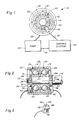
- a controlled replenishing lubrication system illustrated in Figures 1 and 2 is generally designated 10 and includes a bearing cartridge or housing 12.
- a double row bearing is illustrated within housing 12.
- a first bearing set 24 and a second bearing set 26 have an externally driven shaft 14 extending therethrough. Since bearing sets 24,26 are similar,only one will be described in detail.
- Shaft 14 extends through housing 12 and is secured at 13 to rotatably drive an inner race 16.
- a plurality of rolling elements, such as ball 18, are set within a movable retainer or cage 20 which rotates with ball 18 in a raceway defined between the inner rotating race 16 and an outer stationary race 22.
- Bearing sets 24,26 are secured in side-by-side relationship within housing 12 between a flange 28 and a retainer ring 30.
- Sensing means such as a sensor 32, shown in Figures 1,2, and 3, may be mounted adjacent or on housing 12.
- Each bearing set 24, 26 has a reflective ring 34 circumferentally mounted to rotate with shaft 14.
- Each ring 34 includes a dark, non-reflective surface 37 having a plurality of equally spaced light reflective stripes 38 forming an idicia thereon. Stripes 38 extend substantially parallel with the longitudinal axis of shaft 14.
- the retainer or cage 20 shown in Figs. 1 and 2, of each bearing set 24,26 similarly has a non-reflective surface 48 having a plurality of light reflective stripes 50 forming an indicia thereon which extend radially with respect to shaft 14, which is mounted on the end of the cage 20 and cooperative with the sensor 32.
- Sensor 32 is preferably a photo voltaic sensor and includes a pair of galium - arsenide, infra-red emitting diodes 40, 42 and two corresponding photodarlington sensors 44,46.
- the photodiode 40 is aimed at the circumference of the ring 34 while the photodiode 42 is aimed at the surface 48 on cage 20.
- Indicia in the form of stripes 38 and surface 37 of ring 34 produce variations in the reflection of light emitted from diode 40 as a function of the rotation of the shaft 14.
- Stripes 50 and surface 48 of cage 20 also produce variations in the reflections of light emitted from diode 42 as a function of the rotation of the cage 20.
- One photo sensor 44 is aimed at ring 34 while the photo sensor 46 is aimed at the cage 20.
- the variations in reflected light are sensed by photo sensors 44, 46. This produces a fluctuating wave output from photo sensor 46 the frequency of which is proportional to cage speed. A resulting pulse is produced in response to these variations in reflection of the emitted light.
- Pump means 52 is connected at conduit 53 for pumping a suitable lubricant to bearings 24 and 26 in response to speed variations between shaft 14 and cage 20 as sensed by sensor 32. This is accomplished through a control means 54 coupled to sensor 32 at lead 33 and also connected to pump means 52 at connection 55. In this manner, pump means 52 is coupled to respond to commands from control means 54.
- the way the control system works is to measure the cage/shaft speed ratio during a certain period of time, that is defined by a specific number of shaft pulses. The speed ratio is then compared to a limit which has been predetermined. A decrease in EHD film thickness causes an increase in the cage/shaft speed ratio. Every time the ratio exceeds the input limit a pulse is generated and counted. When a specified number of these pulses have been counted within a predetermined time segment, an output pulse is generated to actuate an oil injection pump relay.
- control system might also be configured to examine the rate of change of the ratio or the variability of the ratios as well. Additionally, other control law variations will become obvious to those skilled in the art.
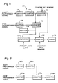
- the fluctuating wave signal from the photo sensor 32 (shown in Figs. 1,2, and 3) is input to a control system generally designated 60 where it is processed in accordance with the associated schematic of Figure 5.
- a signal from the shaft photosensor 44 is input to a buffer 62 where the signal is converted to a clean square wave.
- a buffer 64 converts the fluctuating wave from the cage photosensor 46 to a clean square wave.
- the shaft signal from buffer 62 is fed into a counter 66 where the pulses are summed until a specified number is obtained, normally 1 ⁇ 106 pulses. When this specified number of pulses is reached an output pulse is emitted from counter 66. This pulse is transmitted to two other counters 68 and 70.
- the counter 70 has also been counting pulses from the cage signal buffer 64.
- the pulse from counter 66 stops counter 70, which then contains the total number of cage pulses counted during the accumulation of 1 ⁇ 106 shaft pulses. This total is input to a comparator 72 and a monitor 74 from counter 70.
- the comparator 72 the total number of cage pulses is compared with a preset standard number. If the actual number of cage pulses (or cage/shaft speed ratio) is less than the standard number (preset ratio), the comparator 72 resets and is ready for the next input from counter 70. If the actual number of cage pulses is greater than the standard number, an output pulse is sent to a pump actuation counter 76.
- counter 76 If counter 76 accumulates a specified number of pulses, usually 10, from the comparator 72 before being reset, it transmits a pump actuation signal to a relay 78 which in turn controls the pump 52 to provide a desired amount of lubricant.
- the pump actuation counter 76 receives a periodic reset command from counter 68. When counter 68 has summed input pulses to this predetermined number, it resets itself and sends a signal pulse to reset counter 76.
- FIG. 6 Another possible application for the invention is to monitor the quality of the lubrication in an operating rolling element bearing.
- a processing system is shown in block form in Figure 6.
- This system worked in exactly the same way as the system depicted in Figure 4 up to the output of counter 70a.
- the output of counter 70a goes only to the monitor 74a, which is either at the site of the bearing being measured or telemetered to a more convenient monitoring location.
- This application may be particularly useful for a bearing whose lubrication requirements are not well known.
- the quality of the lubrication i.e. EHD film
- This system could also allow for the timely shutdown or reconfiguration of a system using a bearing whose performance is expected to degrade based on data from the monitor.
- FIG. 7, 8 and 9 Another sensor technique is shown in Figures 7, 8 and 9. Again for illustration , a sensor 132 is shown but it should be recognized that it is only one of a number of sensors that could be used to achieve the same result.
- a single sensor 132 is mounted on or adjacent to the stationary bearing housing 112.
- Sensor 132 consists of a photo diode 142 and a photodarlington sensor 146 arranged in such a way that light emitted from the photodiode 142, upon striking a reflective surface on cage 120, will be reflected back to photosensor 146 and produce a pulse that is sent to a control system.
- a single thin reflective radial line 150 located on an otherwise dark (non-reflective) cage surface 148 would produce a pulse for every revolution of cage 120 if it were not otherwise blocked.
- a dark disk 125 with a single thin radial slot 126 is attached to the shaft 114 or the inner race of the bearing 124 in such a way that, except when slot 126 is aligned with the sensor 132, it prevents light from reaching cage 120. Therefore, a pulse is only generated when both the reflective line 150 on cage 120 and the slot 126 in the disk 125 are aligned with the sensor 132.
- the time between pulses will, therefore, be a function of the speed ratio which is, in turn, a function of the EHD film thickness.
- FIG. 10 One possible control system for a sensor technique of the type shown in Figure 7, 8, and 9 is depicted in block diagram form in Figure 10 and is generally designated 200.
- the pulses from the time interval sensor 132 enter a buffer 201 where the shape of the pulse is more sharply defined.
- a pulse will start a counter 202 which will count pulses from a clock 203 until another pulse is received from buffer 201, at which time the counter 202 will send the number of clock pulses from clock 203 that is has counted in the interval between signal pulses to a monitor 204 and a comparator 205,
- Counter 202 has a dual counting capability so that a signal pulse that stops the counting of clock pulses from clock 203 will also start the counting of clock pulses for the next interval.
- Comparator 205 compares the number received from the counter 202 with a preset time limit which has been predetermined to correspond to the minimum acceptable EHD film thickness. If the interval measured by counter 202 is less than the preset limit, a pulse is provided to a counter 206. If the interval measured by counter 202 is greater than the preset limit, comparator 205 is reset and no output is made. Counter 206 continues to count pulses from comparator 205 until it reaches a predetermined number or until it is reset.
- a relay 207 which activates an oil pump 152 to provide the desired lubricant.
- the output of the clock 203 is simultaneously input to a counter 208 which accumulates pulses until a preset number is reached. Therefore, counter 206 is reset periodically. If it counts the predetermined number of pulses from comparator 205 before it is reset, it will deliver a command to pump relay 207, otherwise it will begin counting as soon as it is reset. This system insures that a real, steady state film thickness change has caused the change in time interval from the sensor signal rather than an inadvertent noise pulse or a transient condition that does not require any action or additional lubrication.
- ratio of the speeds includes the ratio of the cage speed to the shaft speed and also a ratio formed by the difference of the two speeds divided by the shaft speed.
- the inner race 16 could be stationary and the outer race 22 then being rotatable.
- the optical pick-up of the shown embodiments can be replaced by a magnetic, electrostatic or RF pick-up if the environment permits their application.
Landscapes
- Engineering & Computer Science (AREA)
- General Engineering & Computer Science (AREA)
- Mechanical Engineering (AREA)
- Rolling Contact Bearings (AREA)
- Testing Of Devices, Machine Parts, Or Other Structures Thereof (AREA)
Claims (15)
- Gesteuertes Lagerschmierstoff-Zufuhrsystem mita) einem Wälzlager mit relativ zueinander drehbarem Innenring (16) und Außenring (22), die zwischen sich einen Laufweg für die Wälzkörper bilden;b) mehreren geschmierten Wälzkörpern (18), die bei einer relativen Drehbewegung zwischen Innen- und Außenring im Laufweg beweglich sind;
gekennzeichnet durchc) einen mit den Wälzkörpern (18) bewegten Käfig (20) für die Wälzkörper;d) eine auf die Relativbewegung zwischen dem Käfig (20) und einem der drehbaren Laufringe (16 oder 22) ansprechende Fühlereinrichtung (32,34,37,38,48,50,33), welche Änderungen der Schmierfilmdicke entsprechende Signale liefert; unde) eine auf diese Signale ansprechende Steuereinrichtung (54,52,53) zur Aufrechterhaltung der gewünschten Schmierfilmdicke. - System nach Anspruch 1, dadurch gekennzeichnet, daß die Fühlereinrichtung auf das Verhältnis der Geschwindigkeit des Käfigs (20) zur Geschwindigkeit des drehbaren Rings (16,22) anspricht.
- System nach Anspruch 1, dadurch gekennzeichnet, daß die Fühlereinrichtung (132) auf das Zeitintervall zwischen aufeinanderfolgenden Lageübereinstimmungen des Innen- und/oder Außenrings (16,22) mit dem Käfig (120) anspricht, um von Änderungen der Schmierfilmdicke abhängige Signale zu erzeugen.
- System nach Anspruch 1, 2 oder 3, dadurch gekennzeichnet, daß die Steuereinrichtung folgendes umfaßt:
eine Einrichtung (54) zur Erzeugung von Kommandosignalen, sobald die Schmierfilmdicke von einer gewünschten Dicke abweicht; und
eine auf die Kommandosignale ansprechende Pumpeinrichtung (52,152) für die Zufuhr einer gewünschten Schmierstoffmenge. - System nach einem der vorangehenden Ansprüche, dadurch gekennzeichnet, daß die Fühlereinrichtung eine auf die Signale ansprechende Anzeigevorrichtung (74a) für eine die Schmierfilmdicke darstellende Anzeige aufweist.
- System nach einem der vorangehenden Ansprüche mit einem Lagergehäuse (12) sowie einer mit dem drehbaren Lagerring (16) verbundenen Welle (14), dadurch gekennzeichnet, daßa) der Käfig eine erste Licht reflektierende und mit ihm bewegte Marke (50) aufweist;b) die Welle eine zweite Licht reflektierende und mit ihr bewegte Marke (38) aufweist;c) die Fühlereinrichtung (32) benachbart im Gehäuse (12) angeordnet ist und Licht auf die erste und die zweite Marke wirft sowie Änderungen in der Reflexion des Lichtes mißt und die Steuereinrichtung (52,54) auf diese Änderungen anspricht.
- System nach Anspruch 6, dadurch gekennzeichnet, daß die erste Licht reflektierende Marke mehrere reflektierende Streifen (50,38) aufweist.
- System nach Anspruch 6 oder 7, dadurch gekennzeichnet, daß die Fühlereinrichtung Leuchtdioden (40,42) und Photosensoren (44,46) aufweist, wobei eine der Leuchtdioden (42) Licht auf eine erste Gruppe von Streifen (50) und die andere Leuchtdiode (40) Licht auf eine zweite Gruppe von Streifen (38) wirft, einer der Photosensoren (46) die Käfiggeschwindigkeit und der andere Photosensor (44) die Geschwindigkeit des rotierenden Laufrings (16) oder der Welle (14) mißt.
- System nach einem der Ansprüche 6 bis 8, gekennzeichnet durcha) einen an die Fühlereinrichtung (32) angeschlossenen ersten Pufferspeicher (62), der von der Wellendrehzahl abhängige Impulse empfängt und Wellen-Impulse erzeugt;b) einem an die Fühlereinrichtung (32) angeschlossenen zweiten Pufferspeicher (64), der von der Käfigdrehzahl abhängige Impulse empfängt und Käfig-Impulse erzeugt;c) einen ersten Zähler (66) zum Summieren der Wellen-Impulse, der bei Aufsummierung einer vorgegebenen Anzahl von Wellen-Impulsen einen Zähler-Ausgangsimpuls liefert;d) die Ausgangsimpulse des ersten Zählers empfangende zweite (68) und dritte (70) Zähler, wobei der dritte Zähler (70) auch die Käfig-Impulse summiert und vom Ausgangsimpuls des ersten Zählers angehalten wird; unde) einen ein Signal vom dritten Zähler empfangenden Vergleicher (72), der an einen Pumpenbetätigungszähler (76) und ein Pumpenrelais (78) angeschlossen ist und die empfangenen Impulse mit einem vorgegebenen Standard vergleicht, wobei der Vergleicher zurückgesetzt wird, sofern die Käfig-Impulse weniger als der vorgegebene Standard sind, und der Vergleicher Pumpenausgangsimpulse an den Pumpenbetätigungszähler liefert, sofern die Käfig-Impulse mehr als der vorgegebene Standard sind, und wobei ein Pumpenbetätigungssignal für das Pumpenrelais erzeugt wird, sobald der Pumpenbetätigungszähler eine vorgegebene Anzahl von Pumpenausgangsimpulse aufsummiert hat.
- System nach Anspruch 9, dadurch gekennzeichnet, daß der Pumpenbetätigungszähler (76) Rückstellkommandos vom zweiten Zähler (68) empfängt.
- System nach Anspruch 9 oder 10, gekennzeichnet durch eine überwachungseinrichtung (74) für die Aufnahme des Ausgangssignals des dritten Zählers (70).
- System nach Anspruch 7, dadurch gekennzeichnet, daß die lichtempfindliche Marke des Käfigs (120) einen reflektierenden, sich radial erstreckenden Streifen (150) umfaßt.
- System nach Anspruch 12, dadurch gekennzeichnet, daß die lichtempfindliche Marke der Welle eine Scheibe (125) mit einem darin befindlichen, sich radial erstreckenden Schlitz (126) aufweist.
- System nach Anspruch 13, dadurch gekennzeichnet, daß die Fühlereinrichtung (132) eine Leuchtdiode (142) sowie einen Photosensor (146) aufweist, die beide auf den Streifen (150) des Käfigs (120) und den Schlitz (126) in der Maske (125) gerichtet sind.
- System nach Anspruch 12, 13 oder 14 mit einer an die Fühlereinrichtung (132) angeschlossenen Steuereinrichtung (200) zum Steuern einer Pumpvorrichtung (152), gekennzeichnet durcha) einem Pufferspeicher (201) zur Aufnahme von Impulsen aus der Fühlereinrichtung;b) einen ersten Zähler (202);c) einen Taktgeber (203), wobei der erste Zähler Impulse vom Pufferspeicher und vom Taktgeber empfängt;d) einen Vergleicher (205);e) eine überwachungseinrichtung (204), wobei der Vergleicher und die überwachungseinrichtung Ausgangssignale des ersten Zählers aufnehmen;f) einen zweiten Zähler (208);g) einen dritten Zähler (206), wobei der zweite Zähler Signale vom Taktgeber und der dritte Zähler Signale vom Vergleicher und vom zweiten Zähler empfängt; undh) ein Relais (207), welches Signale vom dritten Zähler erhält.
Applications Claiming Priority (2)
| Application Number | Priority Date | Filing Date | Title |
|---|---|---|---|
| US07/043,062 US4738336A (en) | 1987-04-27 | 1987-04-27 | Controlled replenishing lubrication system |
| US43062 | 1987-04-27 |
Publications (3)
| Publication Number | Publication Date |
|---|---|
| EP0288941A2 EP0288941A2 (de) | 1988-11-02 |
| EP0288941A3 EP0288941A3 (en) | 1989-07-12 |
| EP0288941B1 true EP0288941B1 (de) | 1991-12-11 |
Family
ID=21925268
Family Applications (1)
| Application Number | Title | Priority Date | Filing Date |
|---|---|---|---|
| EP88106552A Expired EP0288941B1 (de) | 1987-04-27 | 1988-04-23 | Schmieranlage mit geregelter Auffüllung |
Country Status (5)
| Country | Link |
|---|---|
| US (1) | US4738336A (de) |
| EP (1) | EP0288941B1 (de) |
| JP (1) | JPS63285328A (de) |
| CA (1) | CA1284680C (de) |
| DE (1) | DE3866764D1 (de) |
Families Citing this family (69)
| Publication number | Priority date | Publication date | Assignee | Title |
|---|---|---|---|---|
| NL8700595A (nl) * | 1987-03-12 | 1988-10-03 | Skf Ind Trading & Dev | Aslagersamenstel. |
| US4856617A (en) * | 1987-12-21 | 1989-08-15 | Moore & Steele Corporation | Railway lubricating system and method |
| DE3818256A1 (de) * | 1988-05-28 | 1989-11-30 | Baier & Koeppel | Verfahren zur einstellung der schmierzeit einer schmiermittelpumpe und einrichtung zur durchfuehrung des verfahrens |
| JP2765897B2 (ja) * | 1988-12-23 | 1998-06-18 | 株式会社日立製作所 | 潤滑剤供給方法およびその方法を用いた軸受装置 |
| FR2647182B1 (fr) * | 1989-05-22 | 1992-01-10 | Cit Alcatel | Dispositif pour l'alimentation en graisse de plusieurs paliers |
| US5423399A (en) * | 1993-01-21 | 1995-06-13 | Honeywell Inc. | Gas pressurized oil replenishment system for bearing assemblies |
| JP3313441B2 (ja) * | 1993-02-19 | 2002-08-12 | 光洋精工株式会社 | 転がり軸受潤滑剤供給装置 |
| EP0854314B1 (de) * | 1993-03-18 | 2003-08-20 | B a r m a g AG | Verfahren zur Zuführung von Schmiermittel an ein Wälzlager |
| US5636708A (en) * | 1994-05-16 | 1997-06-10 | Wedeven; Lavern D. | Method and device for broad temperature range vapor lubrication |
| US5620060A (en) * | 1996-02-06 | 1997-04-15 | Ithaco, Inc. | Lubricant replenishment system |
| US6447573B1 (en) | 1997-03-19 | 2002-09-10 | Trico Manufacturing Company | Apparatus and method for lubricant condition control and monitoring |
| US7017712B1 (en) | 1997-03-19 | 2006-03-28 | Trico Mfg. Corp. | Apparatus and method for lubricant condition control and monitoring |
| JP3541806B2 (ja) * | 1997-12-11 | 2004-07-14 | 三菱電機株式会社 | 放電加工装置 |
| FR2775035B1 (fr) * | 1998-02-18 | 2000-03-10 | Snecma | Pilotage du jeu radial d'un roulement |
| US6477885B1 (en) * | 1998-12-25 | 2002-11-12 | Nsk Ltd. | Lubricant applying system for a rolling bearing |
| EP1046794A1 (de) * | 1999-04-19 | 2000-10-25 | Joma-Polytec Kunststofftechnik GmbH | Kühl- und/oder Schmiermittelfördereinrichtung |
| GB9912112D0 (en) * | 1999-05-25 | 1999-07-28 | Rolls Royce Plc | Monitoring of bearing performance |
| US6623251B2 (en) | 1999-06-21 | 2003-09-23 | Nsk Ltd. | Spindle apparatus |
| DE19947458A1 (de) * | 1999-10-02 | 2001-05-31 | Perma Tec Gmbh & Co Kg | Verfahren zur Schmierung eines Wälzlagers |
| US6932856B2 (en) * | 1999-12-08 | 2005-08-23 | Trico Mfg. Corp. | Apparatus and method for lubricant condition control and monitoring from a remote location |
| GB2357556B (en) * | 1999-12-24 | 2002-11-06 | Univ Central Lancashire | Lubrication control system |
| US6357922B1 (en) | 2000-02-24 | 2002-03-19 | The Timken Company | Lubrication system for high speed antifriction bearings |
| AT410431B (de) * | 2000-08-11 | 2003-04-25 | Hy Power Flexomatic Hydraulik | Verfahren zur steuerung der abgabe von schmiermittel |
| JP3994670B2 (ja) * | 2001-02-16 | 2007-10-24 | 株式会社ジェイテクト | 転がり軸受 |
| JP2003042392A (ja) † | 2001-07-27 | 2003-02-13 | I M N Kk | 回転部支持体における潤滑油供給方法 |
| US6791209B2 (en) * | 2002-01-02 | 2004-09-14 | Intel Corporation | Power and control for power supply fans |
| US6819017B2 (en) * | 2002-01-02 | 2004-11-16 | Intel Corporation | Method and apparatus for fan redundancy |
| US6724183B2 (en) * | 2002-01-02 | 2004-04-20 | Intel Corporation | Method and apparatus for detecting bearing failure |
| AU2003254779A1 (en) | 2002-07-29 | 2004-02-16 | Nsk Ltd. | Rolling bearing, grease replenishing device, main shaft device, grease replenishing method, and grease replenishing program |
| JP4089363B2 (ja) * | 2002-09-13 | 2008-05-28 | 株式会社ジェイテクト | 転がり軸受装置 |
| US20040197040A1 (en) * | 2003-04-03 | 2004-10-07 | Steven Walker | Method and device for sensing health and condition of a bearing through the lubrication port of a machine |
| JP4151472B2 (ja) * | 2003-04-25 | 2008-09-17 | 株式会社ジェイテクト | ころ軸受装置およびころ軸受の潤滑方法 |
| US20060073303A1 (en) * | 2004-10-04 | 2006-04-06 | Trico Mfg. Corp. | Flinger disc |
| US7862875B2 (en) * | 2004-10-04 | 2011-01-04 | Trico Corporation | Flinger disc |
| USD589597S1 (en) | 2007-04-04 | 2009-03-31 | Trico Mfg. Corp | Flinger disc |
| DE102007036271A1 (de) * | 2007-07-31 | 2009-02-05 | Baumer Hübner GmbH | Drehgeber mit Überwachung des Lagerverschleißes sowie Verfahren hierzu |
| DE102007062389A1 (de) | 2007-12-22 | 2009-06-25 | Schaeffler Kg | Injektor und Vorrichtung zur dauerhaften Schmierung von Lagern |
| US8096164B2 (en) | 2008-01-17 | 2012-01-17 | Trico Corporation | Apparatus and methods for management of fluid condition |
| US8220671B2 (en) | 2008-03-12 | 2012-07-17 | Trico Corporation | Lubricant dispenser with nozzle |
| EP2128465B1 (de) * | 2008-05-14 | 2011-07-06 | Siemens Aktiengesellschaft | Wälzlager, Wälzkörper für Wälzlager und Gerät mit Wälzlager |
| USD687923S1 (en) | 2008-06-03 | 2013-08-13 | Trico Corporation | Lubricant dispensing nozzle |
| US9109748B2 (en) * | 2008-12-16 | 2015-08-18 | Rockwell Automation Technologies, Inc. | Machine conditioning monitoring closed loop lubrication system and method |
| US8147684B2 (en) * | 2009-03-27 | 2012-04-03 | Trico Corporation | Apparatus and methods for lubricant filtration and drum pump filtration system |
| DE112010003390T5 (de) * | 2009-08-27 | 2012-12-06 | Aktiebolaget Skf | Verfahren und System zum Ermitteln und Ausführen korrekter automatischer Nachschmierung für eine Anzahl von Lagern |
| US8147683B2 (en) * | 2010-01-22 | 2012-04-03 | Trico Corporation | Portable lubricant filtration system and method |
| WO2011130673A2 (en) * | 2010-04-16 | 2011-10-20 | U.E. Systems, Inc. | An ultrasonically controllable grease dispensing tool |
| US8910751B2 (en) * | 2010-06-08 | 2014-12-16 | Flanders Electric Motor Service, Inc. | Bearing lubrication system |
| DE102012100574B4 (de) * | 2011-07-27 | 2022-05-12 | Schuler Pressen Gmbh | Presse mit einer pressenzustandsabhängigen Gleitlagerschmierung und Verfahren zu deren Betrieb |
| US20150068844A1 (en) * | 2012-01-02 | 2015-03-12 | Ingemar Strandell | System & method |
| DE102012200783B4 (de) * | 2012-01-20 | 2013-11-07 | Aktiebolaget Skf | Wälzkörper und Wälzlager |
| DE102012201721A1 (de) * | 2012-02-06 | 2013-08-08 | Schaeffler Technologies AG & Co. KG | Verfahren zum Betrieb einer Wälzlageranordnung und Wälzlagereinrichtung hierzu |
| USD696956S1 (en) | 2012-04-25 | 2014-01-07 | Trico Corporation | Lubricant dispenser |
| USD687921S1 (en) | 2012-04-25 | 2013-08-13 | Trico Corporation | Lubricant dispenser |
| USD687922S1 (en) | 2012-04-25 | 2013-08-13 | Trico Corporation | Lubricant dispenser |
| DE102012015457A1 (de) * | 2012-06-12 | 2013-12-12 | Robert Bosch Gmbh | Vorrichtung und Verfahren zur Verschleißbestimmung |
| DE102013100988A1 (de) * | 2013-01-31 | 2014-07-31 | Baier & Köppel GmbH & Co. | Vorrichtung zur zustandsabhängigen Schmierung wenigstens einer Gleit- und/oder Wälzpaarung |
| JP6160125B2 (ja) | 2013-03-01 | 2017-07-12 | 株式会社ジェイテクト | 転がり軸受装置 |
| DE102013208936A1 (de) * | 2013-05-15 | 2014-11-20 | Schaeffler Technologies Gmbh & Co. Kg | Verfahren zur Steuerung der Einbringung zusätzlichen Schmiermittels in ein mit einem Schmiermittel geschmiertes Lager, insbesondere Wälzlager oder Gleitlager |
| DE102014204062A1 (de) * | 2014-03-06 | 2015-09-10 | Aktiebolaget Skf | Schmiersystem für ein Lager sowie Lager mit einem Schmiersystem und Verfahren zum Schmieren eines Lagers |
| EP3163148B1 (de) * | 2014-06-27 | 2021-02-24 | NTN Corporation | Schmierölzuführungseinheit und lagervorrichtung |
| DE102014219312A1 (de) * | 2014-09-24 | 2016-03-24 | Aktiebolaget Skf | Verfahren und Vorrichtung zum Nachschmieren eines Wälzlagers |
| US9551460B2 (en) * | 2014-12-23 | 2017-01-24 | Lincoln Industrial Corporation | Bearing system with lubrication controller |
| US9695979B2 (en) | 2014-12-23 | 2017-07-04 | Lincoln Industrial Corporation | Method of controlling bearing lubrication system |
| US9841141B2 (en) * | 2014-12-31 | 2017-12-12 | Lincoln Industrial Corporation | Lubrication method for housing having an exclusion seal |
| US9810372B2 (en) * | 2014-12-31 | 2017-11-07 | Lincoln Industrial Coporation | Bearing system with lubricated exclusion seal |
| US10302340B2 (en) | 2015-03-11 | 2019-05-28 | Emerson Climate Technologies, Inc. | Compressor having lubricant management system for bearing life |
| DE102015215302B4 (de) * | 2015-08-11 | 2026-03-12 | Aktiebolaget Skf | Automatisches Schmiersystem für ein Lager und Verfahren zum Betreiben eines automatischen Schmiersystems |
| US10247638B2 (en) * | 2016-11-11 | 2019-04-02 | Korea Institute Of Science And Technology | Bearing test apparatus for testing behavior of the bearing |
| CN115388160B (zh) * | 2022-08-23 | 2025-05-06 | 台州宙义机电股份有限公司 | 一种能润滑自检提示的减速机 |
Family Cites Families (12)
| Publication number | Priority date | Publication date | Assignee | Title |
|---|---|---|---|---|
| US1762566A (en) * | 1929-03-01 | 1930-06-10 | Alemite Corp | Signal for lubricating systems |
| US2545719A (en) * | 1946-05-17 | 1951-03-20 | Stewart Warner Corp | Timing mechanism |
| US2853948A (en) * | 1955-08-19 | 1958-09-30 | Thompson Prod Inc | Lubricating and cooling arrangement for a bearing assembly |
| US3127954A (en) * | 1962-08-24 | 1964-04-07 | Trabon Engineering Corp | Lubrication monitoring system |
| FR1605154A (de) * | 1965-12-16 | 1973-03-23 | ||
| US3561565A (en) * | 1969-09-15 | 1971-02-09 | Dennis Frederick Woor | Pulse-actuated lubrication system |
| DE2025693A1 (de) * | 1970-05-21 | 1971-12-09 | Siemens Ag | Verfahren zur Überwachung des Betriebszustandes von Wälzlagern |
| JPS5413853A (en) * | 1977-07-05 | 1979-02-01 | Nippon Seiko Kk | Roller bearing system |
| DE2907620A1 (de) * | 1979-02-27 | 1980-08-28 | Fraunhofer Ges Forschung | Verfahren und einrichtung zum messen der dicke durchsichtiger duenner schichten, insbesondere schmierstoff-filme |
| GB2111136A (en) * | 1981-12-09 | 1983-06-29 | Rolls Royce | Skid control in rolling bearings |
| DD217599B1 (de) * | 1983-09-20 | 1990-07-18 | Auerbach Werkzeugmaschf Veb | Verfahren zum ueberwachen und bewerten der reibleistungsverhaeltnisse in insbesondere langzeit-fettgeschmierten lagerungen |
| JPS6073124A (ja) * | 1983-09-30 | 1985-04-25 | Toshiba Corp | 回転軸浮上装置 |
-
1987
- 1987-04-27 US US07/043,062 patent/US4738336A/en not_active Expired - Fee Related
-
1988
- 1988-04-19 CA CA000564445A patent/CA1284680C/en not_active Expired - Fee Related
- 1988-04-23 DE DE8888106552T patent/DE3866764D1/de not_active Expired - Fee Related
- 1988-04-23 EP EP88106552A patent/EP0288941B1/de not_active Expired
- 1988-04-27 JP JP63105364A patent/JPS63285328A/ja active Pending
Also Published As
| Publication number | Publication date |
|---|---|
| EP0288941A3 (en) | 1989-07-12 |
| EP0288941A2 (de) | 1988-11-02 |
| US4738336A (en) | 1988-04-19 |
| CA1284680C (en) | 1991-06-04 |
| JPS63285328A (ja) | 1988-11-22 |
| DE3866764D1 (de) | 1992-01-23 |
Similar Documents
| Publication | Publication Date | Title |
|---|---|---|
| EP0288941B1 (de) | Schmieranlage mit geregelter Auffüllung | |
| US8302737B2 (en) | Main-shaft lubrication device | |
| CA2006320C (en) | Method of supplying lubricant and apparatus for the same | |
| US5873658A (en) | Rolling bearing with information sensor | |
| EP3034872B1 (de) | Windkraftanlage ausgerüstet mit einem getriebe | |
| EP2546518B1 (de) | Abrieberkennungsvorrichtung, damit ausgestatteter windkraftgenerator und abrieberkennungsverfahren | |
| US4365851A (en) | Lubricant recirculation system for the bearing of a rotating shaft | |
| CN112747033B (zh) | 具有光学传感器和相关联的槽的轴承 | |
| GB1605054A (en) | Sealing devices | |
| EP0124530B1 (de) | Vorrichtung zur bestimmung des zustands eines kugellagers | |
| US6227710B1 (en) | Rolling bearing with information sensor | |
| US5052518A (en) | Lubrication system for overrunning clutches | |
| CN219997290U (zh) | 旋转系统、激光雷达及车辆 | |
| EP4215301A1 (de) | Lagervorrichtung | |
| CN117751252A (zh) | 波动齿轮装置以及致动器 | |
| US3662857A (en) | Rotary sump with fluid pick-up | |
| EP1277977B1 (de) | Umdrehungsvorrichtung | |
| US4265496A (en) | Apparatus for long-term bearing lubrication | |
| EP4139581B1 (de) | Lagerüberwachung durch drucksensor | |
| US4091663A (en) | Torque indicating device | |
| JPH0634027A (ja) | トルク検出機能付き摩擦伝動装置 | |
| EP1681479A1 (de) | Lageranordnung | |
| JPH10252749A (ja) | 転がり軸受装置 | |
| CN222839491U (zh) | 一种具有防轴承油挥发附着结构的编码器和马达设备 | |
| JPH0753865Y2 (ja) | ベアリング転動体組付装置用偏心カム軸の回転駆動装置 |
Legal Events
| Date | Code | Title | Description |
|---|---|---|---|
| PUAI | Public reference made under article 153(3) epc to a published international application that has entered the european phase |
Free format text: ORIGINAL CODE: 0009012 |
|
| AK | Designated contracting states |
Kind code of ref document: A2 Designated state(s): DE FR GB IT NL |
|
| PUAL | Search report despatched |
Free format text: ORIGINAL CODE: 0009013 |
|
| AK | Designated contracting states |
Kind code of ref document: A3 Designated state(s): DE FR GB IT NL |
|
| 17P | Request for examination filed |
Effective date: 19891117 |
|
| 17Q | First examination report despatched |
Effective date: 19910521 |
|
| GRAA | (expected) grant |
Free format text: ORIGINAL CODE: 0009210 |
|
| AK | Designated contracting states |
Kind code of ref document: B1 Designated state(s): DE FR GB IT NL |
|
| ET | Fr: translation filed | ||
| REF | Corresponds to: |
Ref document number: 3866764 Country of ref document: DE Date of ref document: 19920123 |
|
| ITF | It: translation for a ep patent filed | ||
| PLBE | No opposition filed within time limit |
Free format text: ORIGINAL CODE: 0009261 |
|
| STAA | Information on the status of an ep patent application or granted ep patent |
Free format text: STATUS: NO OPPOSITION FILED WITHIN TIME LIMIT |
|
| 26N | No opposition filed | ||
| PGFP | Annual fee paid to national office [announced via postgrant information from national office to epo] |
Ref country code: FR Payment date: 19930317 Year of fee payment: 6 |
|
| PGFP | Annual fee paid to national office [announced via postgrant information from national office to epo] |
Ref country code: GB Payment date: 19930322 Year of fee payment: 6 |
|
| PGFP | Annual fee paid to national office [announced via postgrant information from national office to epo] |
Ref country code: DE Payment date: 19930323 Year of fee payment: 6 |
|
| PGFP | Annual fee paid to national office [announced via postgrant information from national office to epo] |
Ref country code: NL Payment date: 19930430 Year of fee payment: 6 |
|
| PG25 | Lapsed in a contracting state [announced via postgrant information from national office to epo] |
Ref country code: GB Effective date: 19940423 |
|
| PG25 | Lapsed in a contracting state [announced via postgrant information from national office to epo] |
Ref country code: NL Effective date: 19941101 |
|
| NLV4 | Nl: lapsed or anulled due to non-payment of the annual fee | ||
| GBPC | Gb: european patent ceased through non-payment of renewal fee |
Effective date: 19940423 |
|
| PG25 | Lapsed in a contracting state [announced via postgrant information from national office to epo] |
Ref country code: FR Effective date: 19941229 |
|
| PG25 | Lapsed in a contracting state [announced via postgrant information from national office to epo] |
Ref country code: DE Effective date: 19950103 |
|
| REG | Reference to a national code |
Ref country code: FR Ref legal event code: ST |
|
| PG25 | Lapsed in a contracting state [announced via postgrant information from national office to epo] |
Ref country code: IT Free format text: LAPSE BECAUSE OF NON-PAYMENT OF DUE FEES;WARNING: LAPSES OF ITALIAN PATENTS WITH EFFECTIVE DATE BEFORE 2007 MAY HAVE OCCURRED AT ANY TIME BEFORE 2007. THE CORRECT EFFECTIVE DATE MAY BE DIFFERENT FROM THE ONE RECORDED. Effective date: 20050423 |