EP0288096A2 - Kolbenbrennkraftmotor - Google Patents
Kolbenbrennkraftmotor Download PDFInfo
- Publication number
- EP0288096A2 EP0288096A2 EP88200499A EP88200499A EP0288096A2 EP 0288096 A2 EP0288096 A2 EP 0288096A2 EP 88200499 A EP88200499 A EP 88200499A EP 88200499 A EP88200499 A EP 88200499A EP 0288096 A2 EP0288096 A2 EP 0288096A2
- Authority
- EP
- European Patent Office
- Prior art keywords
- cylinder
- piston
- wall
- combustion engine
- cylinder head
- Prior art date
- Legal status (The legal status is an assumption and is not a legal conclusion. Google has not performed a legal analysis and makes no representation as to the accuracy of the status listed.)
- Withdrawn
Links
Images
Classifications
-
- F—MECHANICAL ENGINEERING; LIGHTING; HEATING; WEAPONS; BLASTING
- F02—COMBUSTION ENGINES; HOT-GAS OR COMBUSTION-PRODUCT ENGINE PLANTS
- F02F—CYLINDERS, PISTONS OR CASINGS, FOR COMBUSTION ENGINES; ARRANGEMENTS OF SEALINGS IN COMBUSTION ENGINES
- F02F1/00—Cylinders; Cylinder heads
- F02F1/18—Other cylinders
-
- F—MECHANICAL ENGINEERING; LIGHTING; HEATING; WEAPONS; BLASTING
- F02—COMBUSTION ENGINES; HOT-GAS OR COMBUSTION-PRODUCT ENGINE PLANTS
- F02B—INTERNAL-COMBUSTION PISTON ENGINES; COMBUSTION ENGINES IN GENERAL
- F02B3/00—Engines characterised by air compression and subsequent fuel addition
- F02B3/06—Engines characterised by air compression and subsequent fuel addition with compression ignition
-
- F—MECHANICAL ENGINEERING; LIGHTING; HEATING; WEAPONS; BLASTING
- F02—COMBUSTION ENGINES; HOT-GAS OR COMBUSTION-PRODUCT ENGINE PLANTS
- F02F—CYLINDERS, PISTONS OR CASINGS, FOR COMBUSTION ENGINES; ARRANGEMENTS OF SEALINGS IN COMBUSTION ENGINES
- F02F1/00—Cylinders; Cylinder heads
- F02F2001/006—Cylinders; Cylinder heads having a ring at the inside of a liner or cylinder for preventing the deposit of carbon oil particles, e.g. oil scrapers
Definitions
- the invention relates to a piston combustion engine comprising an engine block with at least one cylinder, a cylinder head provided with inlet and exhaust channels and closing off the cylinder at one end, and a piston accommodated in the cylinder which is guided reciprocally between a top dead point close to the cylinder head and a bottom dead point at a stroke length therefrom, the piston bearing a number of piston rings that are in sliding contact with the inner wall of the cylinder.
- the invention has for its object to provide a piston combustion engine of the kind set forth in the preamble, in which these symptoms of wear do not occur or only do so to a much lesser degree.
- this is achieved in that at least a portion of the inner wall of the cylinder, between the cylinder head and the level of the uppermost piston ring at the top dead point of the piston, has a greater surface roughness relative to that of the surface of the peripheral wall of the piston above the uppermost piston ring.
- the contamination is preferably deposited on the rougher portion of the cylinder wall over which the piston rings do not move, and not on the piston. It has been found that this step results in any case in a substantial reduction of the above-mentioned wear.
- An additional advantage of the measure according to the invention is that the rougher portion of the cylinder wall will act as a per se known labyrinth, so that the gases encounter an extra resistance during flow between the rougher portion of the cylinder wall and the periphery of the piston. So called “blow-by" is reduced as a result.
- the less smooth forming of the upper portion of the inner wall of the cylinder with which the piston rings do not come into contact can be realised in various ways. For example by etching, knurling or by applying grooves. Preferively however, a fine screw thread is formed in the said portion of the inner wall of the cylinder.
- the part of the inner wall of the cylinder adjacent to the cylinder head remains relatively smooth, so that the gas turbulences in the combustion space that are favourable for good combustion are not inhibited.
- a further favourable development of the engine in accordance with the invention is characterized by the portion of the inner wall of the cylinder with a greater surface roughness being formed by at least a part of the inner wall of a ring arranged for detachment in the engine block.
- the ring can be manufactured relatively simply and formed with a suitable surface roughness on its inner surface, so that extra costs entailed by application of the invention remain limited.
- the ring can easily be replaced. This work can as a result be performed quickly so that in this respect the invention does not increase costs, or hardly does so.
- the portion of the inner wall of the cylinder with the greater surface roughness has an inner diameter different from the nominal cylinder diameter.
- the roughened portion does not obstruct fitting of the piston in the cylinder and particularly the passage of the piston rings, or only does so to a lesser extent.
- the carbon particles on the rougher portion of the cylinder wall instead of on the piston it is not necessary for the rougher portion to have the same nominal diameter as the cylinder.
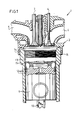
- Engine 1 comprises an engine block in which at least one cylinder bush 2 is mounted. Cylinder 2 is closed off at its top end by a cylinder head 3. Cylinder head 3 is provided with an inlet channel 4 and an exhaust channel 5, which can be opened and closed using an inlet valve 6 and an exhaust valve 7 respectively. Further mounted into cylinder head 3 is an injector 8 with which fuel can be injected into the cylinder.
- piston 9 Fitted in cylinder 2 is a piston 9 which is connected in the known manner to a crankshaft via a drive rod 10. Because of the connection to the crankshaft, piston 9 can move reciprocally between a top dead centre and a bottom dead centre.
- Fig. 2 shows piston 9 at the top dead centre.
- Piston 9 is provided with a number of piston rings 12, which make sliding contact with the inner wall 13 of the cylinder. These piston rings 12 ensure sealing of the piston 9 in the cylinder 2 and the scraping off to the minimum necessary thickness of a film of lubricating oil formed on the inner wall 13 of the cylinder.
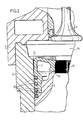
- a portion 15 of inner wall 13 of cylinder 2 is provided at its upper end, that is, at a location between cylinder head 3 and the level of the uppermost piston ring 12 at the top dead centre of piston 9, with a fine screw thread.
- this portion of inner wall 13 has a greater surface roughness than the surface of peripheral wall 17 of piston 9 above the uppermost piston ring 12.
- the portion 15 of the inner wall of cylinder 2 with a greater surface roughness in the direction of cylinder head 3 ends at a distance from cylinder head 3.
- the part of the cylinder wall which in top position of piston 9 forms the side boundary of combustion chamber 14, remains smooth, so that the turbulences of the gases in the combustion chamber 14 that are desirable for a good combustion, are not inhibited.
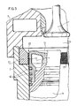
- this embodiment has a releasable ring 20 fitted in the top of the cylinder. A portion of the inner wall of this ring 20 is provided with the greater surface roughness 21. Portion 21 has a larger inner diameter than the nominal cylinder diameter. As a result the slit between the outer surface 17 of the piston and the rough wall portion 21 is bigger, so that during fitting of piston 9, the piston rings 12 can pass through more easily.
- the roughened carbon deposition surface can also be wholly or partly situated on a smaller diameter than the cylinder diameter, above the part of the cylinder wall over which the piston moves. As a result of the preferred deposition of carbon on the roughened surface, less or no carbon deposition onto the piston will be thereby achieved.
Landscapes
- Engineering & Computer Science (AREA)
- Chemical & Material Sciences (AREA)
- Combustion & Propulsion (AREA)
- Mechanical Engineering (AREA)
- General Engineering & Computer Science (AREA)
- Cylinder Crankcases Of Internal Combustion Engines (AREA)
- Lubrication Of Internal Combustion Engines (AREA)
- Pistons, Piston Rings, And Cylinders (AREA)
Applications Claiming Priority (2)
| Application Number | Priority Date | Filing Date | Title |
|---|---|---|---|
| DE8705785U DE8705785U1 (de) | 1987-04-21 | 1987-04-21 | |
| DE8705785U | 1987-04-21 |
Publications (2)
| Publication Number | Publication Date |
|---|---|
| EP0288096A2 true EP0288096A2 (de) | 1988-10-26 |
| EP0288096A3 EP0288096A3 (de) | 1990-02-07 |
Family
ID=6807246
Family Applications (1)
| Application Number | Title | Priority Date | Filing Date |
|---|---|---|---|
| EP88200499A Withdrawn EP0288096A3 (de) | 1987-04-21 | 1988-03-17 | Kolbenbrennkraftmotor |
Country Status (5)
| Country | Link |
|---|---|
| EP (1) | EP0288096A3 (de) |
| JP (1) | JPS63280841A (de) |
| DE (1) | DE8705785U1 (de) |
| FI (1) | FI881791A (de) |
| NO (1) | NO881708L (de) |
Cited By (3)
| Publication number | Priority date | Publication date | Assignee | Title |
|---|---|---|---|---|
| WO2013037063A1 (en) * | 2011-09-12 | 2013-03-21 | Trinity High - Tech Products Ltd. | Modified piston for an internal combustion engine |
| US9359971B2 (en) | 2014-08-21 | 2016-06-07 | General Electric Company | System for controlling deposits on cylinder liner and piston of reciprocating engine |
| WO2021219221A1 (en) * | 2020-04-30 | 2021-11-04 | Wärtsilä Finland Oy | An antipolishing ring |
Families Citing this family (1)
| Publication number | Priority date | Publication date | Assignee | Title |
|---|---|---|---|---|
| DE102020005386A1 (de) * | 2020-09-03 | 2022-03-03 | Deutz Aktiengesellschaft | Brennkraftmaschine mit einem Element an der Zylinderinnenwandung zum Abschaben von Ölkohle |
Citations (4)
| Publication number | Priority date | Publication date | Assignee | Title |
|---|---|---|---|---|
| US2791209A (en) * | 1955-05-25 | 1957-05-07 | Richard H Sheppard | Grooved cylinder liner |
| EP0063258A1 (de) * | 1981-04-18 | 1982-10-27 | Mahle Gmbh | Kombination aus Zylinder und Kolben für Dieselmotoren |
| DE3530875A1 (de) * | 1985-08-29 | 1987-03-05 | Mak Maschinenbau Krupp | Brennkraftmaschine mit laufbuchsenzwischenstueck |
| EP0215511A1 (de) * | 1985-09-11 | 1987-03-25 | KOLBENSCHMIDT Aktiengesellschaft | Kolben-Zylinder-Bausatz für Brennkraftmaschinen |
-
1987
- 1987-04-21 DE DE8705785U patent/DE8705785U1/de not_active Expired
-
1988
- 1988-03-17 EP EP88200499A patent/EP0288096A3/de not_active Withdrawn
- 1988-04-18 FI FI881791A patent/FI881791A/fi not_active IP Right Cessation
- 1988-04-19 JP JP63098041A patent/JPS63280841A/ja active Pending
- 1988-04-20 NO NO881708A patent/NO881708L/no unknown
Patent Citations (4)
| Publication number | Priority date | Publication date | Assignee | Title |
|---|---|---|---|---|
| US2791209A (en) * | 1955-05-25 | 1957-05-07 | Richard H Sheppard | Grooved cylinder liner |
| EP0063258A1 (de) * | 1981-04-18 | 1982-10-27 | Mahle Gmbh | Kombination aus Zylinder und Kolben für Dieselmotoren |
| DE3530875A1 (de) * | 1985-08-29 | 1987-03-05 | Mak Maschinenbau Krupp | Brennkraftmaschine mit laufbuchsenzwischenstueck |
| EP0215511A1 (de) * | 1985-09-11 | 1987-03-25 | KOLBENSCHMIDT Aktiengesellschaft | Kolben-Zylinder-Bausatz für Brennkraftmaschinen |
Cited By (3)
| Publication number | Priority date | Publication date | Assignee | Title |
|---|---|---|---|---|
| WO2013037063A1 (en) * | 2011-09-12 | 2013-03-21 | Trinity High - Tech Products Ltd. | Modified piston for an internal combustion engine |
| US9359971B2 (en) | 2014-08-21 | 2016-06-07 | General Electric Company | System for controlling deposits on cylinder liner and piston of reciprocating engine |
| WO2021219221A1 (en) * | 2020-04-30 | 2021-11-04 | Wärtsilä Finland Oy | An antipolishing ring |
Also Published As
| Publication number | Publication date |
|---|---|
| JPS63280841A (ja) | 1988-11-17 |
| DE8705785U1 (de) | 1988-08-18 |
| EP0288096A3 (de) | 1990-02-07 |
| FI881791A (fi) | 1988-10-22 |
| NO881708D0 (no) | 1988-04-20 |
| FI881791A0 (fi) | 1988-04-18 |
| NO881708L (no) | 1988-10-24 |
Similar Documents
| Publication | Publication Date | Title |
|---|---|---|
| US5253877A (en) | Piston ring having tapered outwardly extending wiper | |
| US5490445A (en) | Ultra low device volume piston system | |
| EP0690250B1 (de) | Zylinder-Einheit und Verfahren zum Herstellen von Laufflächen | |
| US5465691A (en) | Valve guide | |
| JPH0633818B2 (ja) | 内燃機関用のピストンおよびピストンリングユニツト | |
| US5392692A (en) | Antiblow-by piston and seal construction for high temperature applications | |
| US5430938A (en) | Method of making and using a piston ring assembly | |
| US4936269A (en) | Method and apparatus for reduced oil consumption and oil deterioration in reciprocating engines | |
| US5660399A (en) | Piston rings particularly suited for use with ceramic matrix composite pistons and cylinders | |
| WO1997003280A1 (en) | An internal combustion engine having a coke scraping ring in a cylinder | |
| EP0288096A2 (de) | Kolbenbrennkraftmotor | |
| EP0719917B1 (de) | Zylindereinheit und Verfahren zur Formung ihrer Gleitfläche | |
| US6196179B1 (en) | Internal combustion engine | |
| GB1584087A (en) | Piston | |
| US4829955A (en) | Piston cylinder kit for internal combustion engines | |
| US5261362A (en) | Piston assembly having multiple piece compression ring | |
| US4787295A (en) | Piston for internal combustion engines | |
| WO1988000289A1 (en) | Piston rings | |
| US4602598A (en) | Spring and valve skirt | |
| AU683337B2 (en) | Valve guide | |
| GB2125515A (en) | Piston ring lubrication in internal combustion engines | |
| JPS5943477Y2 (ja) | ピストン往復動型内燃機関 | |
| JPS6335174Y2 (de) | ||
| EP1482075A1 (de) | Kolbenringbeschichtung | |
| JPH021466Y2 (de) |
Legal Events
| Date | Code | Title | Description |
|---|---|---|---|
| PUAI | Public reference made under article 153(3) epc to a published international application that has entered the european phase |
Free format text: ORIGINAL CODE: 0009012 |
|
| AK | Designated contracting states |
Kind code of ref document: A2 Designated state(s): AT CH DE FR GB LI NL SE |
|
| PUAL | Search report despatched |
Free format text: ORIGINAL CODE: 0009013 |
|
| AK | Designated contracting states |
Kind code of ref document: A3 Designated state(s): AT CH DE FR GB LI NL SE |
|
| STAA | Information on the status of an ep patent application or granted ep patent |
Free format text: STATUS: THE APPLICATION IS DEEMED TO BE WITHDRAWN |
|
| 18D | Application deemed to be withdrawn |
Effective date: 19900808 |