EP0215511A1 - Kolben-Zylinder-Bausatz für Brennkraftmaschinen - Google Patents
Kolben-Zylinder-Bausatz für Brennkraftmaschinen Download PDFInfo
- Publication number
- EP0215511A1 EP0215511A1 EP86201457A EP86201457A EP0215511A1 EP 0215511 A1 EP0215511 A1 EP 0215511A1 EP 86201457 A EP86201457 A EP 86201457A EP 86201457 A EP86201457 A EP 86201457A EP 0215511 A1 EP0215511 A1 EP 0215511A1
- Authority
- EP
- European Patent Office
- Prior art keywords
- cylinder
- piston
- profiling
- top land
- kit according
- Prior art date
- Legal status (The legal status is an assumption and is not a legal conclusion. Google has not performed a legal analysis and makes no representation as to the accuracy of the status listed.)
- Granted
Links
Images
Classifications
-
- F—MECHANICAL ENGINEERING; LIGHTING; HEATING; WEAPONS; BLASTING
- F02—COMBUSTION ENGINES; HOT-GAS OR COMBUSTION-PRODUCT ENGINE PLANTS
- F02F—CYLINDERS, PISTONS OR CASINGS, FOR COMBUSTION ENGINES; ARRANGEMENTS OF SEALINGS IN COMBUSTION ENGINES
- F02F1/00—Cylinders; Cylinder heads
- F02F1/18—Other cylinders
- F02F1/20—Other cylinders characterised by constructional features providing for lubrication
-
- F—MECHANICAL ENGINEERING; LIGHTING; HEATING; WEAPONS; BLASTING
- F16—ENGINEERING ELEMENTS AND UNITS; GENERAL MEASURES FOR PRODUCING AND MAINTAINING EFFECTIVE FUNCTIONING OF MACHINES OR INSTALLATIONS; THERMAL INSULATION IN GENERAL
- F16J—PISTONS; CYLINDERS; SEALINGS
- F16J10/00—Engine or like cylinders; Features of hollow, e.g. cylindrical, bodies in general
- F16J10/02—Cylinders designed to receive moving pistons or plungers
- F16J10/04—Running faces; Liners
-
- F—MECHANICAL ENGINEERING; LIGHTING; HEATING; WEAPONS; BLASTING
- F02—COMBUSTION ENGINES; HOT-GAS OR COMBUSTION-PRODUCT ENGINE PLANTS
- F02B—INTERNAL-COMBUSTION PISTON ENGINES; COMBUSTION ENGINES IN GENERAL
- F02B3/00—Engines characterised by air compression and subsequent fuel addition
- F02B3/06—Engines characterised by air compression and subsequent fuel addition with compression ignition
Definitions
- the invention relates to a piston-cylinder kit for internal combustion engines, in particular for diesel engines, with a top land clearance of 0.3 to 1.5%, preferably 0.4 to 1.0% of the piston diameter and a circumferential profile attached to the edge area of the cylinder running surface on the combustion chamber side .
- the lubricating oil then no longer has the option of accumulating in the 2 to 10 ⁇ m deep grooves of the honing profile, but is instead pushed from the cylinder surface towards the combustion chamber and burned there. This leads to oil shortages that promote wear and scoring on the piston rings. In addition, small gaps form in the area of the polished cylinder running surface, which the shape filling of the piston rings cannot fully follow, so that their wiping effect significantly decreases and, as a result, the oil consumption increases.
- profiling to the combustion chamber side of the cylinder of diesel engines by shaping, through which the build-up of a hard oil-carbon layer on the top land is completely prevented or at least kept within such narrow limits that the oil consumption and thus also the emissions over the lifetime the internal combustion engine should not rise to an unacceptable level.
- the hard oil coal attached to the top land is continuously removed when the piston in the upper cylinder area changes over by contact with the circumferential profiling, so that the cylinder polishing remains limited to a permissible level.
- a piston-cylinder kit of the design described above to be designed in such a way that the piston can be inserted into the cylinder in the usual manner without the good properties with regard to the lowest oil and fuel consumption and low emissions being impaired.
- This object is achieved in that the tips of the profiling produced by machining lie in the plane of the cylinder running surface. This measure makes it possible to insert the piston into the cylinder bore after installing the cylinder in the engine.
- the profiling of the cylinder running surface has semicircular, arc-shaped, trapezoidal, acute-angled, sawtooth-shaped, angularly symmetrical, sawtooth-shaped, obtuse-angled or a similar shape, wherein the profiling can be arranged in a thread-like manner.
- the depth of the profile waves is max. 50%, preferably 0.5 to 10% of the wall thickness of the cylinder and the distance between the profile waves max. 50%, preferably 3 to 6% of the height of the top land.
- the height of the profile of the cylinder running surface suitably corresponds in whole or in part to the height of the top land.
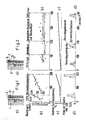
- Fig. La was in a first attempt with a diesel engine with a diesel piston l with a small top land clearance 2 of 0.6% of the piston diameter in the Normally machined cylinder 3 with a diameter of 120 mm.
- the evaluation of the tests shows according to Fig. Lb) that both with a constant load of 110% and with an alternating load, the oil consumption has an increasing tendency.
- the relatively thick oil carbon layer building up on the top land 4 at the top and bottom edge thereof leads to an impermissible cylinder polishing according to FIG. 1 c) according to FIG. 1 b), in particular with alternating loads, so that the measurement was ended after a period of 200 h.
- a diesel piston 5 with a top land game 6 of 0.6% of the piston diameter was inserted into a cylinder 7 with a 120 mm diameter of a diesel engine with supercharging, the tread of which in the area on the combustion chamber side was made with an angularly symmetrical one produced by machining Profile 8 is provided.
- the profile 8 of the cylinder running surface has a considerable reduction in the thickness of the oil carbon layer at the top and bottom edge of the top land 9 and also remains constant over the running time.
- the rate of cylinder polishing is also reduced to an acceptable level, as shown in FIG. 2c).
- the oil consumption remains at a comparatively low level of approx. 0.6 g / kWh at 11% load both with a constant load of 10%, such as with alternating load and with a mixture of constant load and alternating load, over the entire test period and constant at alternating loads of l40 g / h. Since there were no significant changes during the runtime, the test was stopped after 400 hours.
Landscapes
- Engineering & Computer Science (AREA)
- General Engineering & Computer Science (AREA)
- Chemical & Material Sciences (AREA)
- Combustion & Propulsion (AREA)
- Mechanical Engineering (AREA)
- Pistons, Piston Rings, And Cylinders (AREA)
- Cylinder Crankcases Of Internal Combustion Engines (AREA)
Abstract
Description
- Die Erfindung betrifft einen Kolben-Zylinder-Bausatz für Brennkraftmaschinen, insbesondere für Dieselmotoren, mit einem Feuerstegspiel von 0,3 bis l,5 %, vorzugsweise 0,4 bis l,0 % des Kolbendurchmessers und einer am brennraumseitigen Randbereich der Zylinderlauffläche angebrachten umlaufenden Profilierung.
- Die Wirtschaftlichkeit einer Brennkraftmaschine ist nicht nur durch einen niedrigen Kraftstoffverbrauch, sondern auch durch einen möglichst niedrigen Ölverbrauch bestimmt, obwohl letzterer nur einen Bruchteil eines Prozentes des Kraftstoffsverbrauchs beträgt. Erhöhter Ölverbrauch ist nicht nur unwirtschaftlich, sondern führt zudem zu unerwünschten Verkokungserscheinungen im Bereich des Brennraums, des Kolbens und der Ventile, die erhebliche Folgeschäden verursachen können. Größerer Ölverbrauch verschlechtert zusätzlich die Emissionen und führt damit zu einer erhöhten Umweltbelastung. Andererseits ist jedoch bei zu starker Senkung des Ölverbrauchs die Funktion der Brennkraftmaschine infolge zu hohen Verschleisses oder durch Fressen gefährdet. Um die Ölverbrauchsgrenzwerte von ≦ 0,5 g/kWh bei Brennkraftmaschinen, insbesondere bei Nkw-Dieselmotoren, einhalten zu können, wird heute ein beachtlicher Wert auf die Gestaltung und Abstimmung des Kolbens ebenso wie auf die Optimierung der Kolbenringbestückung und Zylinderlauffläche gelegt. Ein besonderes Problem stellt dabei das sogenannte Zylinderpolieren dar, das zu einem Anstieg des Ölverbrauchs über der Laufzeit des Kolbens und darüber hinaus zur Gefahr von Langzeitkolben-Fressern führt. Das Zylinderpolieren wird durch sich im Motorbetrieb am Feuersteg des Kolbens absetzende harte Ölkohle verursacht, durch die infolge der Längs- und Querbewegung des Kolbens das auf der Zylinderlauffläche befindliche Honprofil eingeebnet wird. Das Schmieröl hat dann keine Möglichkeit mehr, sich in den 2 bis l0 µm tiefen Riefen des Honprofils anzusammeln, sondern wird statt dessen von der Zylinderlauffläche in Richtung zum Brennraum geschoben und dort verbrannt. Das führt zu Ölmangelzuständen, die den Verschleiß und die Riefenbildung an den Kolbenringen fördern. Außerdem bilden sich im Bereich der polierten Zylinderlauffläche kleine Spalte, denen die Formfüllung der Kolbenringe nicht vollständig folgen kann, so daß deren Abstreifwirkung deutlich abnimmt und infolgedessen der Ölverbrauch ansteigt.
- Es ist zwar bekannt (SAE-Paper No. 845 0l0), daß durch ein relativ großes Feuerstegspiel von l,5 bis 2,0 % des Kolbendurchmessers die Polierung der Zylinderlauffläche reduziert bzw. ganz vermieden werden kann. Dieser Vorteil muß allerdings mit einer erhöhten Kolbentemperatur, z.B. beim Dieselkolben von 30 bis 50 °C am Rand der Brennraummulde und von 20 bis 30 °C am ersten Kolbenring bzw. an der ersten Kolbenringnut, einer Zunahme des Kraftstoffverbrauchs in der Größenordnung von 2 % sowie mit verschlechterten Emissionen erkauft werden. Es ist zwar möglich, die höhere Kolbentemperatur durch wirksame Kolbenkühlung, den höheren Kraftstoffverbrauch und die verschlechterten Emissionen durch eine Reduzierung der Feuersteghöhe auf 8 bis l0 % des Kolbendurchmessers im Vergleich zur üblichen Höhe von l5 bis l8 % einigermaßen auszugleichen; dennoch entspricht dieses Ergebnis nicht den vom Motorenanwender an zeitgemäße Brennkraftmaschinen gestellten Anforderungen.
- Es ist deshalb vorgesehen, am brennraumseitigen Randbereich der Zylinder von Dieselmotoren durch umformende Bearbeitung eine Profilierung anzubringen, durch die der Aufbau einer harten Ölkohleschicht am Feuersteg ganz verhindert oder doch in so engen Grenzen gehalten wird, daß der Ölverbrauch und damit auch die Emissionen über der Laufzeit der Brennkraftmaschine nicht unzulässig ansteigen. Durch diese Maßnahme wird die am Feuersteg angesetzte harte Ölkohle beim Anlagewechsel des Kolbens im oberen Zylinderbereich durch die Berührung mit der umlaufenden Profilierung ständig abgetragen, so daß die Zylinderpolierung auf ein zulässiges Maß beschränkt bleibt. Da bei einem derartig gestalteten Zylinder die Spitzen der Profilierung als Folge der umformenden Herstellung etwa 0,2 mm über der Ebene der Zylinderlauffläche vorstehen, muß der Kolben von unten her in den noch nicht in den Motor eingebauten Zylinder eingesetzt werden, erst danach folgt die Montage des Zylinders. Ein weiterer Nachteil ist darin zu sehen, daß die Genauigkeit der Profilierung nur in relativ weiten Grenzen reproduzierbar ist.
- Es ist die Aufgabe der vorliegenden Erfindung, einen Kolben-Zylinder-Bausatz der eingangs beschriebenen Ausbildung so zu gestalten, daß der Kolben in üblicher Weise in den Zylinder eingeschoben werden kann, ohne daß die guten Eigenschaften hinsichtlich niedrigstem Öl- und Kraftstoffverbrauch sowie geringen Emissionen beeinträchtigt werden.
- Die Lösung dieser Aufgabe geschieht dadurch, daß die Spitzen der durch spanende Bearbeitung gefertigten Profilierung in der Ebene der Zylinderlauffläche liegen. Durch diese Maßnahme ist es möglich, den Kolben nach dem Einbau des Zylinders in den Motor in die Zylinderbohrung einzuschieben.
- Nach einem besonderen Merkmal der Erfindung besitzt die Profilierung der Zylinderlauffläche halbkreisförmige, bogenförmige, trapezförmige, spitzwinkelförmige, sägezahnförmig-winkelsymmetrische, sägezahnförmig-stumpfwinklige oder eine ähnliche Gestalt, wobei die Profilierung gewindeartig verlaufend angeordnet sein kann.
- Gemäß einem vorzugsweisen Merkmal der Erfindung betragen die Tiefe der Profilwellen max. 50 %, vorzugsweise 0,5 bis l0 % der Wanddicke des Zylinders und der Abstand der Profilwellen max. 50 %, vorzugsweise 3 bis 6 % der Höhe des Feuerstegs.
- Die Höhe der Profilierung der Zylinderlauffläche entspricht zweckmäßig ganz oder teilweise der Höhe des Feuerstegs.
- Die Erfindung ist in der Zeichnung dargestellt und wird nachfolgend näher und beispielsweise erläutert.
- Gemäß Fig. la) wurde in einem ersten Versuch bei einem Dieselmotor mit Aufladung ein Dieselkolben l mit einem kleinen Feuerstegspiel 2 von 0,6 % des Kolbendurchmessers in den normalbearbeiteten Zylinder 3 von l20 mm Durchmesser eingeschoben. Die Auswertung der Versuche zeigt gemäß Fig. lb), daß sowohl bei konstanter Last von ll0 % als auch bei Wechsellast der Ölverbrauch steigende Tendenz besitzt. Die relativ dicke sich am Feuersteg 4 an dessen Ober- und Unterkante aufbauende Ölkohleschicht führt gemäß Fig. lb) insbesondere bei Wechsellast, zu einer unzulässigen Zylinderpolierung gemäß Fig. lc), so daß die Messung nach einer Dauer von 200 h beendet wurde.
- In einem zweiten Versuch wurde nach Fig. 2a) ein Dieselkolben 5 mit einem Feuerstegspiel 6 von 0,6 % des Kolbendurchmessers in einen Zylinder 7 mit l20 mm Durchmesser eines Dieselmotors mit Aufladung eingesetzt, dessen Lauffläche im brennraumseitigen Bereich mit einem durch spanende Fertigung hergestellten winkelsymmetrischen Profil 8 versehen ist.
- Aus Fig. 2d) geht hervor, daß sich die Profilierung 8 der Zylinderlauffläche in einer beachtlichen Verringerung de Dicke der Ölkohleschicht an Ober- und -unterkante des Feuerstegs 9 auswirkt und auch über die Laufzeit konstant bleibt. Demzufolge reduziert sich auch die Rate der Zylinderpolierung, wie Fig. 2c) zeigt, auf ein zulässiges Maß. Der Ölverbrauch bleibt gemäß Fig. 2b) sowohl bei konstanter Last von ll0 %, wie bei Wechsellast als auch bei einer Mischung aus konstanter Last und Wechsellast über die gesamte Versuchsdauer auf vergleichsweise niedrigem Niveau von ca. 0,6 g/kWh bei ll0 % Last und bei Wechsellast von l40 g/h konstant. Da sich keine wesentlichen Änderungen während der Laufzeit zeigten, wurde der Versuch nach 400 h abgebrochen.
Claims (6)
Applications Claiming Priority (2)
| Application Number | Priority Date | Filing Date | Title |
|---|---|---|---|
| DE3532308 | 1985-09-11 | ||
| DE19853532308 DE3532308A1 (de) | 1985-09-11 | 1985-09-11 | Kolben-zylinder-bausatz fuer brennkraftmaschinen |
Publications (2)
| Publication Number | Publication Date |
|---|---|
| EP0215511A1 true EP0215511A1 (de) | 1987-03-25 |
| EP0215511B1 EP0215511B1 (de) | 1989-07-26 |
Family
ID=6280594
Family Applications (1)
| Application Number | Title | Priority Date | Filing Date |
|---|---|---|---|
| EP86201457A Expired EP0215511B1 (de) | 1985-09-11 | 1986-08-22 | Kolben-Zylinder-Bausatz für Brennkraftmaschinen |
Country Status (3)
| Country | Link |
|---|---|
| US (1) | US4829955A (de) |
| EP (1) | EP0215511B1 (de) |
| DE (2) | DE3532308A1 (de) |
Cited By (2)
| Publication number | Priority date | Publication date | Assignee | Title |
|---|---|---|---|---|
| EP0288096A2 (de) * | 1987-04-21 | 1988-10-26 | Stork-Wärtsilä Diesel B.V. | Kolbenbrennkraftmotor |
| EP0943794A1 (de) | 1998-03-18 | 1999-09-22 | Wärtsilä NSD Schweiz AG | Zylinderlaufbuchse |
Families Citing this family (6)
| Publication number | Priority date | Publication date | Assignee | Title |
|---|---|---|---|---|
| GB2294102B (en) * | 1993-12-04 | 1996-06-26 | Ae Goetze Automotive Limited | Fibre-reinforced metal pistons |
| SE510909C2 (sv) * | 1997-01-16 | 1999-07-05 | Volvo Ab | Förbränningmotorkolv |
| US7284961B2 (en) * | 2002-06-06 | 2007-10-23 | Bs&B Safety Systems, Ltd. | Pumping system, replacement kit including piston and/or cylinder, and method for pumping system maintenance |
| CA2710280A1 (en) * | 2007-12-21 | 2009-07-09 | Green Partners Technology Holdings Gmbh | Gas turbine systems and methods employing a vaporizable liquid delivery device |
| US9932930B2 (en) | 2014-01-14 | 2018-04-03 | General Electric Company | Piston with reduced top land height and tight top land piston profile |
| US9359971B2 (en) | 2014-08-21 | 2016-06-07 | General Electric Company | System for controlling deposits on cylinder liner and piston of reciprocating engine |
Citations (4)
| Publication number | Priority date | Publication date | Assignee | Title |
|---|---|---|---|---|
| DE1040841B (de) * | 1957-07-26 | 1958-10-09 | Daimler Benz Ag | Kolben fuer Brennkraftmaschinen |
| GB964618A (en) * | 1962-07-26 | 1964-07-22 | Wellworthy Ltd | Improvements in or relating to cylinders or cylinder liners for internal combustion engines |
| DE2446870A1 (de) * | 1974-09-26 | 1976-04-08 | Sulzer Ag | Kolbenbrennkraftmaschine |
| US4393821A (en) * | 1979-05-22 | 1983-07-19 | Nippon Piston Ring Co., Ltd. | Cylinder or cylinder liner |
Family Cites Families (5)
| Publication number | Priority date | Publication date | Assignee | Title |
|---|---|---|---|---|
| US2085976A (en) * | 1936-02-25 | 1937-07-06 | Heintz & Kaufman Ltd | Cylinder liner |
| US3781022A (en) * | 1969-12-01 | 1973-12-25 | Rikagaku Kenkyusho | Piston ring and cylinder liner having minute oil-retaining indentation |
| US3808955A (en) * | 1972-10-12 | 1974-05-07 | Yanmar Diesel Engine Co | Cylinders of internal-combustion engines |
| DE3029215A1 (de) * | 1980-08-01 | 1982-03-11 | M.A.N. Maschinenfabrik Augsburg-Nürnberg AG, 8900 Augsburg | Brennkraftmaschine mit feingerillten gusseisernen zylinderinnenwaenden |
| JPS583463A (ja) * | 1981-06-30 | 1983-01-10 | Fujitsu Ltd | グラフィックディスプレイ装置のハ−ドコピ−制御方式 |
-
1985
- 1985-09-11 DE DE19853532308 patent/DE3532308A1/de not_active Withdrawn
-
1986
- 1986-08-22 EP EP86201457A patent/EP0215511B1/de not_active Expired
- 1986-08-22 DE DE8686201457T patent/DE3664672D1/de not_active Expired
-
1988
- 1988-05-17 US US07/195,472 patent/US4829955A/en not_active Expired - Fee Related
Patent Citations (4)
| Publication number | Priority date | Publication date | Assignee | Title |
|---|---|---|---|---|
| DE1040841B (de) * | 1957-07-26 | 1958-10-09 | Daimler Benz Ag | Kolben fuer Brennkraftmaschinen |
| GB964618A (en) * | 1962-07-26 | 1964-07-22 | Wellworthy Ltd | Improvements in or relating to cylinders or cylinder liners for internal combustion engines |
| DE2446870A1 (de) * | 1974-09-26 | 1976-04-08 | Sulzer Ag | Kolbenbrennkraftmaschine |
| US4393821A (en) * | 1979-05-22 | 1983-07-19 | Nippon Piston Ring Co., Ltd. | Cylinder or cylinder liner |
Cited By (3)
| Publication number | Priority date | Publication date | Assignee | Title |
|---|---|---|---|---|
| EP0288096A2 (de) * | 1987-04-21 | 1988-10-26 | Stork-Wärtsilä Diesel B.V. | Kolbenbrennkraftmotor |
| EP0288096A3 (de) * | 1987-04-21 | 1990-02-07 | Stork-Wärtsilä Diesel B.V. | Kolbenbrennkraftmotor |
| EP0943794A1 (de) | 1998-03-18 | 1999-09-22 | Wärtsilä NSD Schweiz AG | Zylinderlaufbuchse |
Also Published As
| Publication number | Publication date |
|---|---|
| US4829955A (en) | 1989-05-16 |
| DE3532308A1 (de) | 1987-03-12 |
| DE3664672D1 (en) | 1989-08-31 |
| EP0215511B1 (de) | 1989-07-26 |
Similar Documents
| Publication | Publication Date | Title |
|---|---|---|
| EP1954966B1 (de) | Kolben mit einer unterhalb einer ringnut angeordneten umlaufenden radialen vertiefung | |
| DE112014003421T5 (de) | Gleitanordnung | |
| DE3210771C2 (de) | ||
| DE1601388A1 (de) | Kolben- und Kolbenringanordnung fuer Verbrennungsmotoren | |
| DE2253868A1 (de) | Einteiliger, mit einer pleuelstange verbundener kolben | |
| DE3604661C2 (de) | ||
| DE2458444A1 (de) | Kolben-zylinderanordnung mit verminderter vibration | |
| DE3332358A1 (de) | Kolben fuer verbrennungsmotoren | |
| DE112012003224T5 (de) | Kolben für einen Verbrennungsmotor und Verfahren dafür | |
| EP1092104A1 (de) | Kolbenbolzenbuchse | |
| EP0215511B1 (de) | Kolben-Zylinder-Bausatz für Brennkraftmaschinen | |
| EP1441157B1 (de) | Zylinderoberfläche | |
| DE19848649C2 (de) | Kohlenstoffkolben für eine Brennkraftmaschine | |
| DE2037962A1 (de) | Zylinderlaufbuchse fur Verbrennungs motoren | |
| DE19810309A1 (de) | Druckring, insbesondere Kolbenring für Aluminiumsylinder sowie Verfahren zu dessen Herstellung | |
| EP0171568B1 (de) | Aluminium-Tauchkolben für Verbrennungsmotoren mit Regelstreifen | |
| DE2832953C2 (de) | ||
| WO2000040850A1 (de) | Hubkolbenmaschine | |
| DE102017215335A1 (de) | Zylinderbohrung mit kolbenkinematisch variabler Bohrungsoberfläche, sowie Verfahren zum Herstellen der Zylinderbohrung | |
| DE102021128654A1 (de) | Kolben mit geglätteter äusserer kronenoberfläche in ablagerungsempfindlicher zone | |
| DE60216631T2 (de) | Kolben für verbrennungsmotor | |
| DE3405983C1 (de) | Verschleißfeste Kolbenringnuten an einem aus Vergütungsstahl hergestellten Kolbenoberteil eines Brennkraftmaschinenkolbens | |
| DE102015217023A1 (de) | Zylinderlaufbuchse für eine Brennkraftmaschine, Brennkraftmaschine mit einer solchen Zylinderlaufbuchse und Verfahren zum Herstellen einer Zylinderlaufbuchse für eine Brennkraftmaschine | |
| DE3314330A1 (de) | Halb-t-kompressionsring | |
| DE2748888A1 (de) | Kolbenring |
Legal Events
| Date | Code | Title | Description |
|---|---|---|---|
| PUAI | Public reference made under article 153(3) epc to a published international application that has entered the european phase |
Free format text: ORIGINAL CODE: 0009012 |
|
| AK | Designated contracting states |
Kind code of ref document: A1 Designated state(s): DE FR GB IT |
|
| 17P | Request for examination filed |
Effective date: 19870819 |
|
| 17Q | First examination report despatched |
Effective date: 19880831 |
|
| GRAA | (expected) grant |
Free format text: ORIGINAL CODE: 0009210 |
|
| AK | Designated contracting states |
Kind code of ref document: B1 Designated state(s): DE FR GB IT |
|
| REF | Corresponds to: |
Ref document number: 3664672 Country of ref document: DE Date of ref document: 19890831 |
|
| ITF | It: translation for a ep patent filed |
Owner name: STUDIO JAUMANN |
|
| ET | Fr: translation filed | ||
| GBT | Gb: translation of ep patent filed (gb section 77(6)(a)/1977) | ||
| PLBE | No opposition filed within time limit |
Free format text: ORIGINAL CODE: 0009261 |
|
| STAA | Information on the status of an ep patent application or granted ep patent |
Free format text: STATUS: NO OPPOSITION FILED WITHIN TIME LIMIT |
|
| 26N | No opposition filed | ||
| ITTA | It: last paid annual fee | ||
| PGFP | Annual fee paid to national office [announced via postgrant information from national office to epo] |
Ref country code: DE Payment date: 19920911 Year of fee payment: 7 |
|
| PGFP | Annual fee paid to national office [announced via postgrant information from national office to epo] |
Ref country code: FR Payment date: 19930611 Year of fee payment: 8 |
|
| PGFP | Annual fee paid to national office [announced via postgrant information from national office to epo] |
Ref country code: GB Payment date: 19930817 Year of fee payment: 8 |
|
| PG25 | Lapsed in a contracting state [announced via postgrant information from national office to epo] |
Ref country code: DE Effective date: 19940503 |
|
| PG25 | Lapsed in a contracting state [announced via postgrant information from national office to epo] |
Ref country code: GB Effective date: 19940822 |
|
| GBPC | Gb: european patent ceased through non-payment of renewal fee |
Effective date: 19940822 |
|
| PG25 | Lapsed in a contracting state [announced via postgrant information from national office to epo] |
Ref country code: FR Effective date: 19950428 |
|
| REG | Reference to a national code |
Ref country code: FR Ref legal event code: ST |
|
| PG25 | Lapsed in a contracting state [announced via postgrant information from national office to epo] |
Ref country code: IT Free format text: LAPSE BECAUSE OF NON-PAYMENT OF DUE FEES;WARNING: LAPSES OF ITALIAN PATENTS WITH EFFECTIVE DATE BEFORE 2007 MAY HAVE OCCURRED AT ANY TIME BEFORE 2007. THE CORRECT EFFECTIVE DATE MAY BE DIFFERENT FROM THE ONE RECORDED. Effective date: 20050822 |